the cylinder or the cylinder group to become
operative.
The valves can be energized automatically by e.g.
thermostats in the cold stores, a pressure
controller on the suction line, etc. (see plant
manual).
To each solenoid valve a lamp is connected which
lights up as long as the valve is energized. These
lamps are all mounted on the front panel of a
junction box, in which also the terminals of the
various solenoid valves are located.
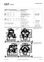
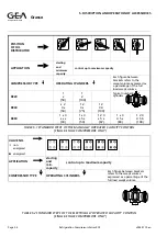
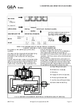
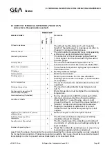
As shown in tables 5.2 and 5.3, the combination
of burning lamps indicates which valves are
energized and consequently which cylinders are in
operation. For this purpose, valves and lamps bear
equal numbers.
In the event of an electric failure, each valve can
be operated indvidually by hand. For this purpose,
a small lever is provided on one side of the valve
housing, which, after being pressed and turned in
the upright(vertical) position, keeps the valve
VALVE NO.
m
non-
energized
l
energized
APPLICATION
starting
minimum
capacity
control up to maximum capacity
COMPRESSOR TYPE
OPERATING CYLINDERS
Each figure between brackets refers to
the swept volume expressed as a
percentage of the full load swept volume
RC219
Cylinder no.1
omitted
•
•
3
•
•
2
3 4
(100)
Typical
numbering
of cylinders
RC429
1
•
•
•
•
•
1
•
•
•
5 6
1 2
•
•
5 6
1 2 3
4 5 6
TABLE 5.3 STANDARD STEPS OF THE ELECTRICALLY OPERATED
CAPACITY CONTROL OF TWO—STAGE COMPRESSORS
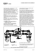
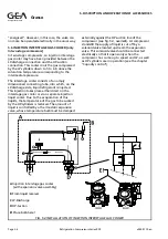
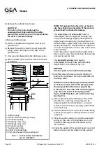
FIG. 5.3 SCHEMATIC DIAGRAM OF ELECTRICALLY OPERATED CAPACITY CONTROL
A
Valve lifting mechanism
B
Oil return to crankcase
C
Oil pump
D
Supply of control oil pressure
E
Three-way solenoid valve
F
Junction box with signal lamps
G
External electrical wiring
Refrigeration Division
Grasso
5. DISCRIPTION AND OPERATION OF ACCESSORIES
v002.97.10.en
Refrigeration Compressors Series RC9
Page 5.5

