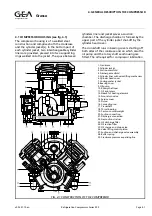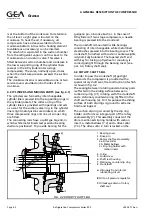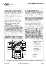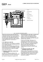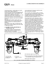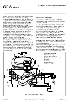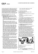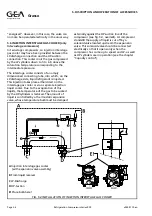
4.1 COMPRESSOR HOUSING (see fig. 4.1)
The compressor housing is of a welded steel
construction and comprises both the crankcase
and the cylinder jacket(s). In the bottom part of
each cylinder jacket, two interchangeable cylinder
liners are provided, pressed into two supporting
rings welded onto the jacket. The space between
cylinders liner and jacket serves as suction
chamber. The discharge chamber is formed by the
upper part of the cylinder jacket shut-off by the
cylinder head cover.
The crankshaft runs in bearing covers shutting off
both sides of the crankcase and on which also the
oil pump and the rotary shaft seal housing are
fitted. The oil required for compressor lubrication
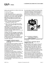
FIG. 4.1 CONSTRUCTION OF THE COMPRESSOR
1. Crankcase
2. Cylinder jacket
3. Suction manifold
4. Discharge manifold
5. Cylinder liner with valve-lifting mechanism
6. Cylinder head cover
7. Cooling water jacket
8. Bearing cover
9. Oil pump
10. Rotary shaft seal
11. Oil sight glass
12. Sleeve for heating element
13. Non-return valve
14. Service cover
15. Piston
16. Connecting rod
17. Crankshaft
18. Thrust bearing
19. Cast-on counterweight
20. Suction connection
21. Discharge connection
22. Gas suction strainer
23. Oil discharge filter
24. Oil suction filter
25. Oil charge and drain valve
26. Valve lifting control piston
27. Suction and discharge valve assembly
28. Buffer spring
29. Crankcase pressure equalizing line
Refrigeration Division
Grasso
4. GENERAL DESCRIPTION THE COMPRESSOR
v002.97.10.en
Refrigeration Compressors Series RC9
Page 4.1


