background image

GE H

EALTHCARE

RAFT

V

OLUSON

 E8 / V

OLUSON

 E6

D

IRECTION

 KTD102576, R

EVISION

 7

DRAFT (A

UGUST

 23, 2012)

 S

ERVICE

 M

ANUAL

5-76

Section 5-16 - Boot Screen Functions

5-16-1-3

Rollback

This function offers the possibility to simply restore the previously used system configuration (rollback), 
which was stored on R:\ during “FMI from DVD”.

1.) Turn system OFF and then back ON.

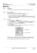
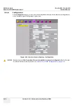
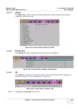
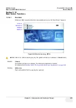
2.) As soon as the “Boot Screen” appears (see: 

Figure 5-52 on page 5-75

), press the 

PG DN


[

 Arrow down] key on the keyboard until the 

Rollback

 item is highlighted, then press 

ENTER

.

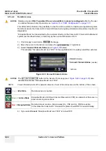
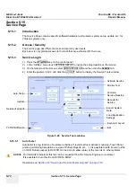
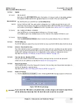
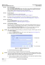
3.) When the following WARNING message appears, press the 

← [

Arrow left] button to highlight OK 

and then press 

ENTER

After performing the rollback, the system reboots. 
The Ultrasound Application is started and finally the 2D screen is displayed on the monitor.

5-16-1-4

Memtest

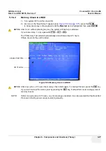
Starts the PC Memory Test.
Operation see: 

Section 5-16-2 "Memory Check in LINUX" on page 5-77

.

Figure 5-53  Warning message

select [OK]

Содержание Voluson E8

Страница 1: ...rt systems with Software version 9 x x BT09 Voluson E6 Voluson E8 Voluson E8 Expert systems with Software version 10 x x BT10 Voluson E6 Voluson E8 Voluson E8 Expert systems with Software version 12 x...

Страница 2: ......

Страница 3: ...LANGUE QUE L ANGLAIS C EST AU CLIENT QU IL INCOMBE DE LE FAIRE TRADUIRE NE PAS TENTER D INTERVENTION SUR LES QUIPEMENTS TANT QUE LE MANUEL SERVICE N A PAS T CONSULT ET COMPRIS LE NON RESPECT DE CET AV...

Страница 4: ...PACIENTE DEVIDO A CHOQUES EL TRICOS MEC NICOS OU OUTROS ESTE MANUAL DE ASSIST NCIA EST DISPON VEL APENAS EM INGL S SE QUALQUER OUTRO SERVI O DE ASSIST NCIA T CNICA QUE N O A GEHC SOLICITAR ESTES MANU...

Страница 5: ...LIST MATERIAALIA TARVITTAVAN K NN KSEN HANKKIMINEN ON ASIAKKAAN VASTUULLA L YRIT KORJATA LAITTEISTOA ENNEN KUIN OLET VARMASTI LUKENUT JA YMM RT NYT T M N HUOLTO OHJEEN MIK LI T T VAROITUSTA EI NOUDATE...

Страница 6: ...BSLU N HO PERSON LU NEBO PACIENT VLIVEM ELEKTRICK HOP PROUDU RESPEKTIVE VLIVEM K RIZIKU MECHANICK HO PO KOZEN NEBO JIN MU RIZIKU DENNE SERVICEMANUAL FINDES KUN P ENGELSK HVIS EN KUNDES TEKNIKER HAR BR...

Страница 7: ...LI B TI SU EISTAS D L ELEKTROS SM GIO MECHANINI AR KIT PAVOJ DENNE SERVICEH NDBOKEN FINNES BARE P ENGELSK HVIS KUNDENS SERVICELEVERAND R TRENGER ET ANNET SPR K ER DET KUNDENS ANSVAR S RGE FOR OVERSETT...

Страница 8: ...TISMENT AR PUTEA DUCE LA R NIREA DEPANATORULUI OPERATORULUI SAU PACIENTULUI N URMA PERICOLELOR DE ELECTROCUTARE MECANICE SAU DE ALT NATUR OVAJ PRIRU NIK ZA SERVISIRANJE DOSTUPAN JE SAMO NA ENGLESKOM J...

Страница 9: ...IJENTA PROUZRO ENE STRUJNIM UDAROM MEHANI KIM I DRUGIM OPASNOSTIMA T TO SERVISN PR RU KA JE K DISPOZ CII LEN V ANGLI TINE AK Z KAZN KOV POSKYTOVATE SLU IEB VY ADUJE IN JAZYK AKO ANGLI TINU POSKYTNUTIE...

Страница 10: ...ILAVUZUN NG L ZCE DI INDAK B R D LDE OLMASINI STERSE KILAVUZU TERC ME ETT RMEK M TER N N SORUMLULU UNDADIR SERV S KILAVUZUNU OKUYUP ANLAMADAN EK PMANLARA M DAHALE ETMEY N Z BU UYARININ G Z ARDI ED LME...

Страница 11: ...GE HEALTHCARE VOLUSON E8 VOLUSON E6 DIRECTION KTD102576 REVISION 7 SERVICE MANUAL ix ZH CN KO...

Страница 12: ...ified GE Healthcare personnel In performing all electrical work on these products GE will use its own specially trained field engineers All of GE s electrical work on these products will comply with t...

Страница 13: ...uplicated in any form in whole or in part without prior written permission of GE Healthcare GE Healthcare may revise this publication from time to time without written notice TRADEMARKS All products a...

Страница 14: ...ate new parts Pages Revision Pages Revision Pages Revision Title Page 7 Chapter 3 Setup Instructions pages 3 1 to 3 70 7 Chapter 9 Renewal Parts pages 9 1 to 9 48 7 Important Precautions pages i to xi...

Страница 15: ...ortant Conventions 1 7 Conventions Used in this Manual 1 7 Standard Hazard Icons 1 8 Product Labels and Icons 1 8 Safety Considerations 1 11 Introduction 1 11 Human Safety 1 11 Mechanical Safety 1 11...

Страница 16: ...GE HEALTHCARE VOLUSON E8 VOLUSON E6 DIRECTION KTD102576 REVISION 7 SERVICE MANUAL xiv Table of Contents System Manufacturer 1 17...

Страница 17: ...Outlets 2 3 Main Power Plug 2 3 EMI Limitations 2 4 Probe Environmental Requirements 2 5 Time and Manpower Requirements 2 5 System Specifications 2 5 Physical Dimensions of Voluson E8 Voluson E6 2 5...

Страница 18: ...9 Connecting the LCD Monitor 3 10 Connecting the Black White Printer 3 11 Connection Scheme B W Printer 3 12 Connecting the Color Printer 3 13 Connection Scheme Color Printer 3 14 Connecting the Desk...

Страница 19: ...olor Printer 3 36 Printer Installation manually 3 37 Adjustment of Printer Settings 3 41 UP D897 Printer Settings 3 42 P95D Printer Settings 3 43 CP30D Printer Settings 3 44 UP D25MD Printer Settings...

Страница 20: ...e Dataflow Concept 3 59 Dataflow Examples 3 60 Stand alone Voluson E8 Voluson E6 3 61 Voluson PC with 4D View Software within a Sneaker Net 3 61 Connection between Voluson and DICOM Server 3 61 Wirele...

Страница 21: ...Modes 4 12 B Flow Check 4 12 XTD View Check 4 12 Coded Contrast Imaging Check 4 13 M Mode Checks 4 14 MCFM Mode Check 4 15 Spectral Doppler Mode Checks 4 16 Color Doppler Mode Checks 4 17 Volume Mode...

Страница 22: ...Database Preset Configurations and Images 4 32 Save Image Settings Only Save Small Backup Scan Settings 4 33 Load Image Settings Only Load Small Backup Scan Settings 4 34 Preparations 4 34 Load Compl...

Страница 23: ...Tissue Doppler 5 8 Pulsed PW Doppler 5 8 3D Imaging 5 8 3D Data Collection and Reconstruction 5 8 3D Image Presentation 5 9 3D Rendering 5 9 Block diagram Voluson E8 Voluson E6 5 10 Data Flow Control...

Страница 24: ...C flow 5 19 SonoNT 5 20 SonoIT 5 20 SonoBiometry 5 20 Elastography 5 20 Elastography Analysis 5 21 SRI Advanced Speckle Reduction Imaging 5 21 V SRI Volume Speckle Reduction Imaging 5 21 Expert Upgrad...

Страница 25: ...stribution Board Top 5 53 RTT Block Diagram 5 53 Control Console 5 54 Monitor 5 57 External I O 5 58 Peripherals 5 59 Recording Tools 5 59 DVD Recorder 5 59 Printers 5 59 Black White Digital Printer 5...

Страница 26: ...n 5 67 Error Logs 5 68 Diagnostics 5 68 Image Quality 5 69 Calibration 5 69 Configuration 5 70 Utilities 5 71 Replacement 5 71 PM 5 71 Service Page 5 72 Introduction 5 72 Access Security 5 72 Service...

Страница 27: ...GE HEALTHCARE VOLUSON E8 VOLUSON E6 DIRECTION KTD102576 REVISION 7 SERVICE MANUAL Table of Contents xxv GE Service 5 75 Rollback 5 76 Memtest 5 76 Memory Check in LINUX 5 77...

Страница 28: ...djust Monitor Settings 6 2 Brightness and Contrast 6 3 Backlight Brightness and Sharpness 6 3 Color Temperature RGB 6 4 Color Calibration 6 5 Monitor Arm Adjustment 6 6 Control Console Positioning 6 7...

Страница 29: ...d System Data 7 10 Export System Data by pressing the ALT D key 7 10 Export Log s and System Data via Service Page 7 11 Dump file 7 11 Remote Access to Service Platform 7 12 General 7 12 How the Custo...

Страница 30: ...Drive resp DVR Drive Tests 7 27 Export images from Local Archive to DVD CD R RW 7 27 Record Spectral Doppler display via DVR Drive BT12 BT13 only 7 29 Network Troubleshooting 7 30 No Connection to the...

Страница 31: ...Procedure 8 11 Image Settings Only Loading Procedure 8 12 Introduction 8 12 Loading Procedure 8 12 Full Backup Full System Configuration Loading Procedure 8 12 Introduction 8 12 Loading Procedure 8 1...

Страница 32: ...8 20 Probe Holder endocavity Removal Procedure 8 20 Probe Holder endocavity Installation Procedure 8 20 Replacement of the Trackball Ring 8 20 Manpower 8 20 Trackball Ring Replacement Procedure 8 20 R...

Страница 33: ...als at a later date 8 25 Manpower 8 25 Tools 8 25 Mounting Replacing the VGA Image Video Resizer 8 26 Installation Procedure at systems WITH power connector 8 26 Installation Procedure at systems WITH...

Страница 34: ...ain Board Module 9 13 FrontEnd US Part Components 9 13 BackEnd PC Part Components 9 16 Options and Upgrades 9 18 Miscellaneous Cables 9 21 Optional Peripherals and Accessories 9 30 Recording Tools 9 3...

Страница 35: ...GE HEALTHCARE VOLUSON E8 VOLUSON E6 DIRECTION KTD102576 REVISION 7 SERVICE MANUAL Table of Contents xxxiii CW Doppler Pencil Probes 9 45 Biopsy Needle Guides 9 46...

Страница 36: ...ance 10 5 System Maintenance 10 6 Preliminary Checks 10 6 Functional Checks 10 7 System Checks 10 7 Peripheral Option Checks 10 8 Mains Cable Inspection 10 8 Optional Diagnostic Checks 10 8 Physical I...

Страница 37: ...d to Lead Leakage Test Record 10 21 Isolated Patient Lead Sink Leakage Isolation Test 10 22 Isolated Lead sink Leakage Test Record 10 22 Probe Leakage Current Test 10 23 Definition 10 23 Tools 10 23 G...

Страница 38: ...GE HEALTHCARE VOLUSON E8 VOLUSON E6 DIRECTION KTD102576 REVISION 7 SERVICE MANUAL xxxvi Table of Contents...

Страница 39: ...and contains the following chapters 1 Chapter 1 Introduction Contains a content summary and warnings 2 Chapter 2 Site Preparation Contains pre installation requirements 3 Chapter 3 Setup Instructions...

Страница 40: ...E8 Console 220V CHINA BT10 H48681CC Voluson E8 Console 240V INDIA BT10 H48681KA Voluson E8 Console 230V 50Hz BT12 H48681RK Voluson E8 Console 115V USA BT12 H48681RL Voluson E8 Console 100V JAPAN BT12...

Страница 41: ...sole 240V INDIA BT10 H48681JZ Voluson E8 Expert Console 230V 50Hz BT12 H48681RD Voluson E8 Expert Console 115V USA BT12 H48681RE Voluson E8 Expert Console 100V JAPAN BT12 H48681RF Voluson E8 Expert Co...

Страница 42: ...E6 Console 240V INDIA BT10 H48681JX Voluson E6 Console 230V 50Hz BT12 H48681KZ Voluson E6 Console 115V USA BT12 H48681LA Voluson E6 Console 100V JAPAN BT12 H48681LB Voluson E6 Console 230V KOREA BT12...

Страница 43: ...T10 Voluson E6 systems with Serial Number D55001 BT12 Voluson E6 systems with Serial Number D58001 BT13 Voluson E6 systems with Software version 9 0 x BT09 Voluson E6 systems with Software version 10...

Страница 44: ...ully read and understood before operating the Voluson E8 and or Voluson E6 and also kept near the system for quick reference The online versions of the operator manual is available via the Help functi...

Страница 45: ...ecautionary message Known or potential hazards are labeled in one of following ways NOTE Notes provide important information about an item or a procedure Information contained in a NOTE can often save...

Страница 46: ...describes the purpose and location of labels safety icons and other important information provided on the equipment Table 1 4 Standard Hazard Icons ELECTRICAL MECHANICAL RADIATION LASER HEAT PINCH Tab...

Страница 47: ...of water IPX 1 protected against dripping water IPX 7 protected against the effects of immersion various Equipment Type BF man in box symbol IEC 60878 5333 indicates B Type equipment having even more...

Страница 48: ...cannot be presented on the device itself various CAUTION Dangerous electric voltage lightning flash with arrowhead is used to indicate electric shock hazards Unplug the main plug before opening the s...

Страница 49: ...8 Voluson E6 weighs 130 kg or more depending on installed peripherals 300 lbs or more when ready for use Care must be used when moving it or replacing its parts Failure to follow the precautions liste...

Страница 50: ...the risk of a probe accidentally falling do not allow the probe cables to become entangled or to be caught in the system s wheels Never immerse the probe connector or adapter into any liquid NOTE For...

Страница 51: ...rve the instructions given in the manual of the peripheral auxiliary device For hardware installation procedures see Chapter 3 Connection of Auxiliary Devices on page 3 9 NOTICE NOTICE The system inte...

Страница 52: ...sion Product labels and its location depend on BT version and or date of manufacture Refer to Section 1 2 3 on page 1 8 and Chapter 2 in the Basic User Manual of your system BT Version BT Version The...

Страница 53: ...decontaminated prior to shipment Under no circumstance should a part or equipment with visible body fluids be taken or shipped from a clinic or site for example body coils or and ultrasound probe The...

Страница 54: ...etic fields electrostatic discharge and disturbances in the electrical power supply For applicable standards please refer to Chapter 2 in the Basic User Manual of the Voluson E8 Voluson E6 ultrasound...

Страница 55: ...sistance Location Phone Number USA GE Medical Systems Ultrasound Service Engineering 9900 Innovation Drive RP 2123 Wauwatosa WI 53226 USA Service On site Service Parts Applications support 1 800 437 1...

Страница 56: ...GE HEALTHCARERAFT VOLUSON E8 VOLUSON E6 DIRECTION KTD102576 REVISION 7 DRAFT AUGUST 23 2012 SERVICE MANUAL 1 18 Section 1 5 Customer Assistance This page was intentionally left blank...

Страница 57: ...2 1 Overview 2 1 1 Purpose of this Chapter This chapter provides the information required to plan and prepare for the installation of a Voluson E8 Voluson E6 ultrasound system Included are description...

Страница 58: ...elected to minimize possible interference 2 2 2 Electrical Requirements NOTE GE Healthcare requires a dedicated power and ground for the proper operation of its Ultrasound equipment This dedicated pow...

Страница 59: ...e present within 1 m 3 2 ft of the system Electrical installation must meet all current local state and national electrical codes 2 2 2 5 Main Power Plug The Voluson E8 Voluson E6 ultrasound system is...

Страница 60: ...noisy images Check grounding of the power cord and power outlet Replace and or reassemble all screws RF gaskets covers and cores After you finish repairing or updating the system replace all covers an...

Страница 61: ...3 2 2 6 2 Acoustic Noise Output max 55 dB A 2 2 6 3 Electrical Specifications Please refer to Section 2 2 2 1 Voluson E8 Voluson E6 Power Requirements on page 2 3 NOTICE NOTICE SYSTEMS AND ELECTRONIC...

Страница 62: ...des The purchaser of GE equipment must only utilize qualified personnel to perform electrical servicing on the equipment The desire to use a non listed or customer provided product or to place an appr...

Страница 63: ...he Voluson E8 Voluson E6 has four outlets inside the system One is for the monitor and three for on board peripherals In case of network option An active network outlet in the vicinity of the ultrasou...

Страница 64: ...Recommended Ultrasound Room Layout Figure 2 1 below shows a floor plan illustrating the recommended layout of the Ultrasound Room and depicting the minimal room layout requirements Figure 2 1 Recommen...

Страница 65: ...e on board monitor and peripherals enabling viewing to be done while scanning continues With DICOM images can be archived stored and retrieved faster easier and at a lower cost 2 3 4 4 DICOM Option Pr...

Страница 66: ...GE HEALTHCARERAFT VOLUSON E8 VOLUSON E6 DIRECTION KTD102576 REVISION 7 DRAFT AUGUST 23 2012 SERVICE MANUAL 2 10 Section 2 3 Facility Needs This page was intentionally left blank...

Страница 67: ...cking the Equipment 3 4 3 4 Preparing for Set Up 3 7 3 5 Connection of Auxiliary Devices 3 9 3 6 Completing the Set Up 3 31 3 7 Printer Installation 3 36 3 8 System Configuration 3 49 3 9 Available Pr...

Страница 68: ...after arriving at site may cause the system to be damaged Table 3 2 Acclimation Time C 60 55 50 45 40 35 30 25 20 15 10 5 0 5 10 15 20 25 30 35 40 F 140 131 122 113 104 96 86 77 68 59 50 41 32 23 14...

Страница 69: ...prevent electrical shock connect the system to a properly grounded power outlet DO NOT use a three to two prong adapter This defeats safety grounding CAUTION CAUTION DO NOT wear the ESD wrist strap w...

Страница 70: ...avity tilt and drop indicator Have two people available to unpack the Voluson E8 Voluson E6 Attempts to move the system considerable distances or on an incline by one person alone could result in pers...

Страница 71: ...ox Afterwards pull out all the horizontal wooden racks for accessories finally remove also the vertical board Check whether delivery is complete according to packing list and check visual damage The e...

Страница 72: ...monitor Caution Two people are needed in the next step due to the weight of the equipment 5 Disengage the brakes grasp the system at the handle then slowly move system down the ramp bottom side of th...

Страница 73: ...e control console for missing or damaged items After switching on the system verify the proper illumination of all the control panel buttons 4 Probes Check all probes for wear and tear on the lens cab...

Страница 74: ...system at least 15 feet away from equipment that emits strong electromagnetic radiation Operate the system in an area enclosed by walls floors and ceilings comprised of wood plaster or concrete which...

Страница 75: ...son E6 system please review Chapter 1 Auxiliary Devices Safety on page 1 12 NOTICE NOTICE It is impossible to attach a Black White printer a Color printer and a DVD recorder in the console at the same...

Страница 76: ...KTD102576 REVISION 7 DRAFT AUGUST 23 2012 SERVICE MANUAL 3 10 Section 3 5 Connection of Auxiliary Devices 3 5 1 Connecting the LCD Monitor NOTE The LCD monitor comes pre installed with the system Figu...

Страница 77: ...the Voluson E8 Voluson E6 system as described in Section 3 6 2 on page 3 31 All software drivers are pre installed for the designated Black White printer only 5 After physical connection to the Voluso...

Страница 78: ...ction Scheme B W Printer Figure 3 6 B W Printer connection text Console back DVD Writer I O UI Top ECG S Video Out In Out DVI Out Mic Line Out In to USB3 A B C D E DVI Out DVI In Monitor RS 232 USB UI...

Страница 79: ...Voluson E6 system as described in Section 3 6 2 on page 3 31 All software drivers are pre installed for the designated Color printer only 5 After physical connection to the Voluson E8 Voluson E6 syste...

Страница 80: ...3 1 Connection Scheme Color Printer Figure 3 7 Color Printer connection text DVI Out PC USB5 USB6 LAN Console back DVD Writer I O RS 232 Out USB3 Audio USB4 DVI In Monitor UI Top ECG S Video Out In Ou...

Страница 81: ...indicated USB port E on the RTB Distribution Board Bottom Figure 3 8 DeskJet Color Printer connection via Bluetooth Adapter text Console back DVD Writer I O UI Top ECG S Video Out In Out DVI Out Mic L...

Страница 82: ...nd if necessary change the Recorder Type see Section 3 8 1 7 on page 3 52 d Assign the recorder control to a remote key P1 P2 P3 and or P4 as described in Section 3 7 5 Remote Control Selection on pag...

Страница 83: ...1 Connection Scheme DVD Recorder Figure 3 9 DVD Recorder connection text Console back DVD Writer I O UI Top ECG S Video Out In Out DVI Out Mic Line Out In A B C D E to USB port A DVI Out DVI In Monito...

Страница 84: ...4 Press the down button on the front of the recorder repeatedly until the SETUP MENU item is highlighted NOTE Each time you press the up or down button the highlight cursor moves up down item by item...

Страница 85: ...Interface 3 5 5 2 2 Changing TV System Video Format NOTE To check Video format needed see Table 3 6 TV System and Region Code on page 3 21 1 If not already done switch on the Sony DVO 1000MD DVD reco...

Страница 86: ...n 10 Press the right button The TV System Sub menu appears 11 Select the appropriate video signal by pressing the up or down button respectively To check the video signal see Table 3 6 TV System and R...

Страница 87: ...button repeatedly until REGION CODE is highlighted 7 Press the right button The Region Code Menu appears 8 Select the appropriate region code by pressing the up or down button respectively To check t...

Страница 88: ...connected to any accessible USB port of the Voluson E8 Voluson E6 NOTE Connection of the WLAN Adapter is always the same no differences between PC Motherboard and or BT version of the system NOTE Aft...

Страница 89: ...8 25 NOTICE NOTICE The VGA Image Video Resizer is required whenever the used Secondary Patient Monitor has a different screen resolution than the Voluson E8 Voluson E6 system Figure 3 18 Connection Sc...

Страница 90: ...all image quality due to lower sensitivity on electromagnetic interferences 3 Set Brightness Contrast for best and detailed image display a Press MENU key select Picture Adj using the On Screen Menu b...

Страница 91: ...systems mains supply directly Always connect it to the supplied Isolation Transformer The Secondary Monitor is the only item to be connected to the Transformer NOTICE NOTICE The 19 LCD Secondary Monit...

Страница 92: ...ext Console back DVD Writer I O S Video Out In Out DVI Out A B C D E Lift is only used for the lifter 230V can not be changed 19 LCD Secondary Monitor appropriate VGA cable connected to the rear side...

Страница 93: ...always the same no differences between PC Motherboard and or BT version of the system After physical connection adjust the Footswitch Left Right as described in Section 3 8 1 8 How to adjust function...

Страница 94: ...f the ECG is always the same no differences between PC Motherboard and or BT version of the system Figure 3 22 Connection Scheme ECG preamplifier text Console back DVD Writer I O UI Top ECG S Video Ou...

Страница 95: ...e the system is powered ON or after shutdown The Voluson E8 Voluson E6 Windows detects the device and automatically installs a driver During this process several dialogs may pop up starting with the F...

Страница 96: ...Drives window shows all USB and Network drives connected to the system Using this dialog the USB devices can be stopped before they are physically disconnected To stop the external device select it a...

Страница 97: ...a power source plug for example a three prong to two prong converter WARNING WARNING WARNING The system s power must be supplied from a separate properly rated outlet to avoid risk of fire Refer to S...

Страница 98: ...including the Back end Processor starts and the operating system is loaded which then leads the application software to activate the scanner The system automatically performs an initialization sequenc...

Страница 99: ...t Screen is displayed Voluson is highlighted Figure 3 27 below 3 Back End Processor is turned ON and starts to load the software 4 The Start Screen Voluson is displayed on the monitor 5 Start up progr...

Страница 100: ...fter complete power down unscrew the 2 screws and remove the pull out protection to disconnect the main power cable from the system or unplug it from the AC wall outlet socket 6 Press on the brakes to...

Страница 101: ...rface 4 Twist the probe locking lever clockwise to vertical position to lock it in place 5 Open the side door lay the cable into the intended cable holder and close the door 6 Carefully position the p...

Страница 102: ...Installing Digital Color Printer 1 Power off Shutdown the system as described in Section 3 6 3 on page 3 34 2 Connect and install the printer as described on page 3 13 CAUTION CAUTION The Bluetooth Pr...

Страница 103: ...e of the screen select CONNECTIVITY and then click on the PERIPHERALS tab 4 Click the ADD PRINTER button see Figure 3 32 above Please read the displayed message carefully and click YES if you have ski...

Страница 104: ...inter Installation 3 7 3 Printer Installation manually cont d 7 Select the corresponding Printer Port e g Figure 3 34 USB001 and click NEXT 8 In the following window select the HAVE DISK button 9 Use...

Страница 105: ...Printer Installation manually cont d 10 Click OPEN select the xxx inf file and click OPEN again 11 Verify the selected Printer Driver path and confirm with OK 12 Select the manufacturer and model of y...

Страница 106: ...lete the manual Printer Installation with the FINISH button NOTE If the message The software you are installing for this hardware has not passed Windows appears click CONTINUE ANYWAY 16 Close all open...

Страница 107: ...EDIT button 5 Confirm the warning message with the YES button The Printer Properties appear To adjust the UP D897 B W Printer see Section 3 7 4 1 UP D897 Printer Settings To adjust the P95D B W Print...

Страница 108: ...elow and select Paper 960x1280 Orientation Portrait Interpolation Method Bilinear 3 Select the DENSITY ADJUST page see Figure 3 41 above and select Gamma TONE2 Sharpness 0 Dark 0 Light 0 Sharpness 2 4...

Страница 109: ...UNC button on the printer and adjust Gamma to r5 by using the turning knob e Press the BRT button twice to save and exit 2 Assign the Printer to the remote keys P1 P2 P3 and or P4 see Section 3 7 5 Re...

Страница 110: ...er Preferences operation see Section 3 7 4 Adjustment of Printer Settings 3 Select the PAPER page see left image at Figure 3 45 and select Paper Size L large Orientation Landscape recommended when usi...

Страница 111: ...see left image at Figure 3 45 and select Paper Size UPC L large UPC S small Orientation Landscape recommended when using large paper size High Speed check mark on 3 Select the GRAPHICS page From the...

Страница 112: ...a Curve Curve 1 c Color Correction set Printer Hardware Color Correction d Gray Balance X 50 Y 50 e Adjustment by Color Color region Magenta Red 4 Save the adjusted printer settings with APPLY and OK...

Страница 113: ...3 45 on page 3 45 3 Select the GRAPHICS page From the Color Adjust pop up menu select a Color Balance Cyan 0 Magenta 0 Yellow 0 b Gamma Select Gamma 1 c Color Correction set Printer Hardware Color Cor...

Страница 114: ...ed Printer for the remote control button Recorder Control Check mark this item to use the selected P key for Recorder Control NOTE Optionally the Printer Remote Control can be done by the Foot switch...

Страница 115: ...t switch assignment Add Printer Edit Printer settings etc Device Setup to set up all DICOM Archive and Network configuration nodes Button Configuration to adjust assignment of Remote keys P1 P2 P3 e g...

Страница 116: ...e System Setup as described in Section 3 8 1 1 on page 3 49 2 On the left side of the screen select GENERAL and then click on the GENERAL tab 3 Select the text box to enter a new Clinic Name with the...

Страница 117: ...assword NOTE A new screen lock password must be at least 6 characters long and has a maximum length of 80 characters The password must contain at least 2 non letter characters 0 9 or c Retype new Pass...

Страница 118: ...elect CONNECTIVITY and then click on the PERIPHERALS tab 3 Depending on the used Recorder type click the field VCR DVD Sony JVC or internal DVR Drive 4 Click SAVE EXIT to save Settings and exit System...

Страница 119: ...s etc 3 8 2 1 To invoke the Setup procedure In general operations are done with the trackball and the trackball keys mouse emulation NOTICE NOTICE Parameters and possible adjustments mostly depend on...

Страница 120: ...B Port Table 9 15 Mitsubishi P95D Digital Color Printer SONY UP D23MD obsolete USB Port Table 9 15 UP D25MD Mitsubishi CP30D Color Deskjet Printer Bluetooth Hewlett Packard HP HP 5940 obsolete USB Por...

Страница 121: ...3 USB 2 0 port 4 USB Table 3 13 USB 2 0 port 5 S Video OUT Table 3 14 S Video Out Connector Figure 3 55 External I O Connectors on Back of Console Table 3 9 External I O Connector Description Item Con...

Страница 122: ...ernal I O Pin Outs Figure 3 56 External I O Connectors next to DVD or DVR Drive Table 3 10 External I O Connector Description Item Connector Name Table Number Description 1 USB Table 3 13 USB 2 0 port...

Страница 123: ...ernet TD 6 ETHER RD Ethernet TD Others NC No connection Table 3 13 USB Connectors Pin No Output Signal Description 1 VCC USB Power Supply 2 Data USB Data 3 Data USB Data 4 GND USB Power Ground Table 3...

Страница 124: ...ection 3 10 Software Option Configuration For description refer to Section 3 8 1 System Setup on page 3 49 and Section 3 8 2 Measure Setup on page 3 53 Table 3 16 DVI D OUT Connector Pin No Descriptio...

Страница 125: ...ve data because no network is available see Section 3 11 1 4 on page 3 61 Voluson E8 Voluson E6 and DICOM server in a network see Section 3 11 1 5 on page 3 61 3 11 1 1 The Dataflow Concept Communicat...

Страница 126: ...C with 4D View The local database is used for patient archiving Images are stored to internal hard drive The local database is used for patient archiving Afterwards images are stored to a DVD CD or ex...

Страница 127: ...Voluson E6 Physical Connection No network connection needed 3 11 1 5 Connection between Voluson and DICOM Server In this configuration the Voluson E8 Voluson E6 is configured to work with a DICOM serv...

Страница 128: ...e 3 22 2 Press the UTILITIES key on the control panel and touch SYSTEM SETUP to invoke setup desktop 3 On the left side of the screen select CONNECTIVITY and then click the DEVICE SETUP tab 4 Click th...

Страница 129: ...ter Network Name SSID and check adjust all other settings NOTE For detailed description of available parameters refer to Section 3 11 2 1 Description of Netgear Configuration Parameters on page 3 64 7...

Страница 130: ...ss point Network Type Specifies the type of network in which your client adapter is installed Default Access Point Infrastructure Access Point Infrastructure Connect to an access point or router with...

Страница 131: ...ktop on the screen 3 On the left side of the screen select CONNECTIVITY and then click the DEVICE SETUP tab 4 Click the NETWORK CONFIGURATION button read the message and confirm with YES 5 The Interne...

Страница 132: ...ected to a shared network drive of another server 5 Enter the name of the shared network folder in the Network Folder Name field 6 Supply a valid user name and a password for this folder NOTE If you c...

Страница 133: ...ction a warning message appears inside the dialog In this case please verify the data in the dialog NOTICE NOTICE If there already is a connection to the remote server the CONNECT button is grayed To...

Страница 134: ...Services Destination Devices TCP IP Settings Device Type Manufacturer Name IP Address Port AE Title 1 2 3 4 5 6 7 8 9 10 11 12 Dept Voluson E8 Voluson E6 Type Floor Room REV Comments CONTACT INFORMAT...

Страница 135: ...Figure 3 66 Worksheet for DICOM Network Information Voluson E8 Voluson E6 Host Name AE Title Local Port IP Address Net Mask ROUTING INFORMATION ROUTER2 ROUTER3 ROUTER1 Destination IP Addresses GATEWAY...

Страница 136: ...at all relevant safety and user information is available during the operation and service of the complete system 3 14 1 Product Locator Installation NOTE The Product Locator Installation Card shown ma...

Страница 137: ...tabase Preset Configurations and Images 4 32 4 6 Software Configuration Checks 4 45 4 7 Peripheral Checks 4 46 4 8 Mechanical Function Checks 4 47 4 9 Site Log 4 48 Section 4 2 Required Equipments An...

Страница 138: ...when all board covers and frame panels are securely in place The covers are required for safe operation good system performance and cooling purposes NOTICE NOTICE Lockout Tagout Requirements For USA o...

Страница 139: ...ON position before starting the system However be aware some auxiliary equipment may switch itself to standby mode e g Color video printer and must therefore be switched on separately As soon as the...

Страница 140: ...fter complete power down unscrew the 2 screws and remove the pull out protection to disconnect the main power cable from the system or unplug it from the AC wall outlet socket 6 Press on the brakes to...

Страница 141: ...nel rotary toggle flip switch controls 10 Button for Control Panel Rotation 3 TGC Slider Controls 11 Mode keys rotary controls used in 3D 4D Mode 4 Screen Format keys 12 Keyboard and F1 key to invoke...

Страница 142: ...Main mode is displayed 3 Setting window shows all settings for the active application The active one is highlighted 4 Additional functions which are supported by the selected Mode NOTE Different menus...

Страница 143: ...Status area of P1 P2 P3 and P4 keys 4 Probe Application 18 Status area of current operation state Freeze Run Cine 5 Depth Frame rate 19 Status area of the trackball and trackball keys 6 Mechanical In...

Страница 144: ...e 4 16 PW Pulsed Wave Doppler CW Continuous Wave Doppler Color Doppler Modes see Section 4 4 5 on page 4 17 CFM Color Flow Mode PD Power Doppler TD Tissue Doppler HD Flow Bi Directional Angio Volume M...

Страница 145: ...ct the depth position of the actual focus zone s Arrows at the left edge of the 2D Image mark the active focal zone s by their depth position 4 Depth Adjusts the penetration depth range of the ultraso...

Страница 146: ...ction Imaging is a smoothing type filter to reduce speckle in the ultrasound image 14 2D 2D SRI Changes the Single image display to two simultaneous half images The left frame shows only the 2D Mode i...

Страница 147: ...ofter image This function is only available if XBEAM CRI is switched off 28 CRI FILTER If this filter is set to high the XBeam CRI image is smoothed CRI Filter setting off leads to a sharper impressio...

Страница 148: ...User Manual 4 4 2 2 XTD View Check For further details refer to the Voluson E8 Voluson E6 Basic User Manual B Flow On Off switch Press the BF key to activate deactivate the B Flow mode Figure 4 9 B F...

Страница 149: ...ecks 4 13 4 4 2 Additional optional Operating Modes cont d 4 4 2 3 Coded Contrast Imaging Check For further details refer to the Voluson E8 Voluson E6 Basic User Manual Coded Contrast Imaging On Off s...

Страница 150: ...e sensitivity brightness of the entire M image 4 M Mode Depth Common with 2D Mode Depth 5 AMM optional Anatomical M Mode displays a distance time plot from a cursor line 6 Display Format e g In the Du...

Страница 151: ...unctional Checks 4 15 4 4 3 1 MCFM Mode Check For further details refer to the Voluson E8 Voluson E6 Basic User Manual By pressing the M control and the C control the MCFM mode is switched on in the p...

Страница 152: ...only available with linear probes 5 SPEED By touching up or down four different sweep speeds can be selected 6 RT TRACE Real Time Auto Trace The envelope curve of the Doppler spectrum maximum velociti...

Страница 153: ...y to adjust the Bi Directional Angio Gain Rotate the C MODE key to adjust the Tissue Doppler Gain 3 STEERING Beam Steering is only possible with linear probes in CFM PD and HD Flow Mode 4 2D 2D C PD H...

Страница 154: ...ove and under the color scale in kHz cm s or m s 18 CFM MAP PD HD Flow TD Provides selectability of the color coding for an optimization of the display of blood flow similar to the post processing cur...

Страница 155: ...nus e g 4D Real Time Table 4 6 Pre Volume Mode Functions Step Task Expected Results 1 AQUISITION 3D STATIC 3D Volume Mode Static volume acquisition also in combination with PD HD Flow or CFM 4D REAL T...

Страница 156: ...start the Volume acquisition 8 VISUALIZATION After resp during Volume Mode Acquisition RENDER After the 3D acquisition the system switches automatically to the read menu The selected format will be p...

Страница 157: ...re compiled to a 3D section aspect The aspect shows a quasi spatial cut into the reference image 4 REF IMAGE To select the Reference image among A B C or 3D 5 INIT Resets rotations and translations of...

Страница 158: ...ection keys are not available in Static 3D Sectional Planes 4 3D 4D INFO On Off switch to show full or reduced Image Info parameter on screen 5 3D COLOR OFF On Off switch to show an acquired 3D CFM 3D...

Страница 159: ...ay the images one by one 4 4 7 4 Spectral Doppler or M Cine Loop Press FREEZE then roll the TRACKBALL to display the Cine Loop one by one The UPPER TRACKBALL KEY changes from the 2D Cine to the D Loop...

Страница 160: ...ter 3D Volume or Real Time 4D acquisition touch the CINE CALC key on the Touch Panel 2 Choose desired Cine Calc display mode 3 Select Step Size and Reference image 4 Select the START IMAGE and the END...

Страница 161: ...E key on the Touch Panel press the CLEAR ALL key on the control panel or the DELETE MEAS key on the keyboard NOTE To alternate the control from one cursor to the other press CHANGE the upper trackball...

Страница 162: ...unction without completing the measurement touch EXIT on the Touch Panel press the CALIPER key again or press EXIT on the control panel 4 4 8 3 Volume Measurements 1 Press the CALIPER key and then tou...

Страница 163: ...determination of the envelope curve requires a clear and low noise record of the Doppler spectrum Otherwise the reliability of the displayed measurement results may not be ensured 4 4 8 4 2 Manual Tra...

Страница 164: ...and storage of measuring marks is done with SET right or left trackball key To change measuring marks before completion press CHANGE upper trackball key Depending on the setting in the Measure Setup...

Страница 165: ...ng key causes loading of the preset The probe is initialized the Touch Panel shows the main menu 2D mode and the ultrasound image appears on the monitor in write mode real time display 4 4 10 3 Deacti...

Страница 166: ...or patient Via the DATA TRANSFER button it is possible to send images over the DICOM network print exams images export exams images import exams images etc Image History Image History gives you acces...

Страница 167: ...ct CONNECTIVITY and then click the DRIVES tab 4 Click the ERASE CD button to displays the Erase DVD CD window as shown in Figure 4 21 5 Select the Erase Mode and click the OK button to start the proce...

Страница 168: ...n page 4 34 B Full System Configuration Section 4 5 3 Save Full System Configuration Full Backup on page 4 37 Section 4 5 4 Load Full System Configuration Full Backup on page 4 39 Section 4 5 5 Delete...

Страница 169: ...ect an external USB device 2 Press the UTILITIES key on the control panel 3 In the Utilities menu touch SYSTEM SETUP to invoke the setup desktop on the screen 4 On the left side of the screen select B...

Страница 170: ...se the media and click LOAD NOTE If it is desired to load settings from media Internal HDD click on the CHANGE FOLDER button browse for the folder D usersettings FactoryDefault V830 and then click the...

Страница 171: ...t settings which are adapted for the installed Application Software version 1 Perform Preparations on page 4 34 2 Select the Complete Backup marked blue see Figure 4 25 below and click the button to c...

Страница 172: ...grams for new probe etc 1 Perform Preparations on page 4 34 2 Click the sign next to Complete Backup to open the content tree 3 Click the sign next to UserPrograms select the desired probe s and copy...

Страница 173: ...omputer name Service Platform state of the Service Software NOTE It is recommended to Full Backup system configuration data before upgrading the software and or image settings presets This ensures tha...

Страница 174: ...5 13 on page 3 30 Figure 4 28 directory structure of full backup data Figure 4 29 Other drive drop down menu NOTICE NOTICE When the backup is saved to an external USB device the system has to be infor...

Страница 175: ...not possible to load restore all the data The following rules specify these restrictions 1 Generally only restoring data from an older to a newer software version is possible Loading a backup into a s...

Страница 176: ...then click the SYSTEM CONFIGURATION tab 4 Click the LOAD button of the Full System Configuration group 5 Choose the Destination 6 Click on the backup to be restored additional information is displaye...

Страница 177: ...panel 2 In the Utilities menu touch SYSTEM SETUP to invoke the setup desktop on the screen 3 On the left side of the screen select BACKUP and then click the SYSTEM CONFIGURATION tab 4 Click the DELETE...

Страница 178: ...ss the UTILITIES key on the control panel 2 In the Utilities menu touch SYSTEM SETUP to invoke the setup desktop on the screen 3 On the left side of the screen select BACKUP and then click the IMAGE A...

Страница 179: ...ter the description of the image backup 11 Select the NEXT button 12 To start the backup process click YES NOTICE NOTICE If for example All images older than 1 Day is chosen see Figure 4 36 on page 4...

Страница 180: ...Click the LOAD button see Figure 4 35 on page 4 42 5 Choose the Destination 6 Click on the backup to be restored additional information is displayed in the table 7 Select the NEXT button The followin...

Страница 181: ...ettings settings assigned as desired by the customer 7 Scan Assistant Check settings settings assigned as desired by the customer Table 4 10 System Setup Checks ADMINISTRATION Step Page Task Expected...

Страница 182: ...sk Expected Result s 1 Measure Calc Check all settings for all applications setting assigned as desired by the customer 2 Application Parameters Check all settings for all applications setting assigne...

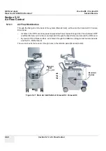
Страница 183: ...can be rotated translated and adjusted in height electronically only NOTE For further details refer to Section 5 11 3 on page 5 63 and or Section 6 5 on page 6 7 4 8 2 Brakes and Direction Swivel Lock...

Страница 184: ...E8 VOLUSON E6 DIRECTION KTD102576 REVISION 7 DRAFT AUGUST 23 2012 SERVICE MANUAL 4 48 Section 4 9 Site Log Section 4 9 Site Log Table 4 16 Voluson E8 Voluson E6 Site Log Paper Documentation Date Servi...

Страница 185: ...bsystem function It also describes the Power Distribution System PDS and probes 5 1 2 Contents in this Chapter 5 1 Overview 5 1 5 2 General Information 5 2 5 3 FrontEnd Processor 5 24 5 4 BackEnd Proc...

Страница 186: ...D View Contrast Imaging etc Color Doppler Imaging CFM PD TD and HD Flow M Mode MCFM Imaging Doppler PW CW 3D Mode and Real Time 4D Imaging Different combinations of the above modes Figure 5 1 Voluson...

Страница 187: ...he FrontEnd FE Electronics to the BackEnd Processor BEP and finally is displayed on the LCD monitor and peripherals Voluson E8 Voluson E6 internal electronics are divided into three Front End FE Proce...

Страница 188: ...Power Supply Secondary RTN Power Supply Primary RTB Distribution Board Bottom PC Box PC Motherboard with Processor and Memory ADD2 DVI Card at VE6 Graphic Card at VE8 RTV Videoboard GES 15 I O Connect...

Страница 189: ...s clinical applications Any 3 probes may be connected at the same time 1 pencil CW probe Medical application fields include Obstetrics Gynecology and Fertility Radiology Internal Medicine Neurology Ca...

Страница 190: ...solution excellent acoustic clutter rejection and an easy to operate user interface Coded Harmonics enhances near field resolution for improved small parts imaging as well as far field penetration It...

Страница 191: ...s colors being used to represent blood flow velocity variance power and or direction Often to provide spatial orientation the full color blood flow cross section is overlaid on top of the grayscale cr...

Страница 192: ...Doppler can be used in combination with 2D and Color Flow modes 5 2 1 5 3D Imaging The Voluson E8 Voluson E6 Ultrasound System will be used to acquire multiple sequential 2D images which can be combin...

Страница 193: ...changing direction of observation helps the observer to separate the features in the volume according to their distance from the observer 5 2 1 8 3D Rendering The 3D volume rendering is a calculation...

Страница 194: ...K Mainboard PCI 32 Bit 33 MHz 132 MB s PCI Expr RTB Distribution Board RTN Primary Power Supply Monitor Serial ATA RTH RTT DVI out RTF ProbeConnect FPGA RSR RSR RST RST BF Rx Data LVDS 14 pairs 50MHz...

Страница 195: ...o the new order shot1pix1 shot1pix2 shot1pix3 shot2pix1 shot2pix2 shot2pix3 After DC cancelling the signal is mixed with RX Frequency and brought to LF Spectrum where the LowPassFilter cuts HF Mixer a...

Страница 196: ...g adaption of Brightnesses they are composed to one whole RX Line c XBEAM CRI CrossBeam Compound Resolution Imaging Does not need any special functions of RFI Image is composed of more than one differ...

Страница 197: ...the ECG Curve is inside PC Memory Software has to take care that D Mode Image and ECG Curve are placed exactly one upon the other means have the same Cine Shift 2 RTV Video section see 5 2 3 1 B Mode...

Страница 198: ...e 4D Mode nonstop volume rendering see 5 2 3 1 B Mode 5 2 3 8 XBeam CRI Mode CrossBeam Compound Resolution Imaging see 5 2 3 1 B Mode 5 2 3 9 VCI Mode Volume Contrast Imaging see 5 2 3 1 B Mode 5 2 3...

Страница 199: ...art Diagnosis 1 1 1 1 1 1 SonoAVC SonoAVC General Sono Automated Volume Count 1 1 1 1 1 1 1 1 1 1 1 1 SonoVCAD labor SonoVCAD labor 1 1 1 1 1 1 1 1 1 1 1 1 Anatomical M Mode Anatomical M Mode AMM X X...

Страница 200: ...D transducers to automatically scan multiple adjacent slices and delivers a real time display of the ROI This image results from a special rendering mode consisting of texture and transparency informa...

Страница 201: ...n be drawn Volumes from older BT s can be loaded and edited with VCI Omni View without any limitations Volumes can be edited in all other Visualization Modes Dual Format is now also possible in Render...

Страница 202: ...g follicles in a volume of an organ e g ovary and analyze their shape and volume From the calculated volume an average diameter can be calculated It also lists the objects according to their size Each...

Страница 203: ...STIC M Mode Creates a M spectrum from a STIC acquisition capture of a full fetal heart cycle in real time saved as a volume for later analysis After activating STIC M Mode the STIC cine is running and...

Страница 204: ...de inner HC Head circumference AC Abdomen circumference FL Femur length BPD HC combined measurement The measurement mode can be changed from automatic to manual Available measurement methods depend on...

Страница 205: ...filtering technique that permits effective speckle reduction in real time The speckle reduction filter is available to the user in all B mode imaging independent of the transducer used 5 2 4 20 V SRI...

Страница 206: ...the operator and is done by adjusting the location of the M line The CW Doppler beam or M mode line can be steered allowing interrogation along an operator selected line within the image This option c...

Страница 207: ...bal Service Platform Software Software Options D User partition User Presets Backup database Images Archive Patient ID s and Reports database Service database System settings database R Rescue partiti...

Страница 208: ...RFI Radio Frequency Interface Controller Board 5 30 Figure 5 5 Front End Processor Block diagram BackEnd RFI RF Interface RSR RST RTM Rx Tx Motherboard RTP Secondary Power Supply Probe Code Select ser...

Страница 209: ...25 Figure 5 7 Voluson E6 RTF Beamformer RTM on page 5 26 Figure 5 6 Voluson E8 RTF Beamformer RTM RST Transmitter Subboard RSR Receiver Subboard RST Transmitter Subboard RSR Receiver Subboard RTF Prob...

Страница 210: ...ower MOT signals CTRL signals Tx Rx Power MOT signals CTRL signals Tx Rx 256 Tx Rx Channels Rx Channels multiplexed SIN COS Mot Strobes CTRL signals PowerSupply RTK Motherboard EBF_D 18 Probe 3 Probe...

Страница 211: ...Motherboard contains 16 8 pcs of RSR see Section 5 3 3 RSR Beamformer Receiver Subboards on page 5 28 16 12 pcs of RST see Section 5 3 4 RST Beamformer Transmitter Subboards on page 5 28 1 optional RS...

Страница 212: ...mer Frontend Probe Connector Relais RFI RF Interface Board RF Data Sync BF Koeff Tx Trig BF Koeff Tx Trig BF Koeff Tx Trig Probe RTM Beamformer Motherboard RTF Probe Connector Board Voluson E8 BT09 10...

Страница 213: ...Anti Aliasing filter for ADC ADC 18 Bit 390 kHz FPGA for Controlling Mid Board Interface 5 3 6 RTK Motherboard Connects the following boards components connection board only no active electronics RTF...

Страница 214: ...xchange Interface RTF Frontend Board Cache Controller interface 1 5D and 1 25D probes Interface for programming the RTF FPGA RTP Secondary Power Supply Probe Select Interface SIN COS for 3D 4D probes...

Страница 215: ...pter 5 Components and Functions Theory 5 31 5 3 7 1 RFI Board Interface FPGA A DMA logic B Beamformer Interface C RSW FPGA programming interface D RTF FPGA programming interface E RTF FPGA programming...

Страница 216: ...Board 5 34 5 4 6 RTB Distribution Board Bottom 5 36 Figure 5 10 BackEnd Processor Block diagram RTP Secondary Power Supply Console User Interface PC Motherboard RTV Video Management Legacy Analog Vid...

Страница 217: ...ns For further details see Section 5 2 6 Data Location on page 5 23 5 4 2 PC Motherboard 5 4 2 1 KONTRON Dual core or DFI Dual core Built in or external Components On Board VGA LAN USB 2 0 Sound CPU 2...

Страница 218: ...ormation coming from the Graphic Card at Voluson E8 respectively the ADD2 DVI Graphic Adapter Card at Voluson E6 to the DVI D digital and DVI I integrated connectors Converts DVI D inputs to S Video o...

Страница 219: ...Chapter 5 Components and Functions Theory 5 35 5 4 5 RTV Video Management Board cont d Figure 5 11 RTV Block diagram Figure 5 12 RTV Video I O Flash contains minimum configuration for DVI Output Monit...

Страница 220: ...r and Amplifier for PC Sound Doppler Audio and VCR DVD Recorder 5 4 6 1 RTB Block Diagram Figure 5 13 RTB Block diagram 3V3 Voltage Regulator USB 2 0 Hub Controller 7 Port USB Port Power Switch USB Po...

Страница 221: ...5 38 DFI Dual core PC Motherboard is installed see Figure 5 15 on page 5 39 Voluson E6 BT10 Kontron Dual core PC Motherboard is installed see Figure 5 16 on page 5 40 DFI Dual core PC Motherboard is i...

Страница 222: ...Out PCI Exp ADD2 S ATA GES15 I O RTH USB USB USB PWR PWR USB Console back RTP Conn 1 Conn 2 Conn 3 Monitor PWR DVI RTU User Interface Module Speaker DVD Writer HDD IDE PWR Brake Fan Fan Fan From RTN A...

Страница 223: ...SB USB USB PWR PWR USB RTT PWR Console back RTP Conn 1 Conn 2 Conn 3 Monitor PWR DVI RFI RTK RTF RTM Probe Connectors RTU User Interface Module Lifter Speaker DVD Writer HDD IDE PWR 230V Brake Fan Fan...

Страница 224: ...through PCI Exp U4 PCI Exp ADD2 USB 3 Printer BW DVD Rec DVD Writer IDE PWR Console back GES15 In Out PC RTB USB A C B D E Console ECG RFI RTK RTF RTM Probe Connectors To RTP Conn 1 2 3 RTT PWR RTH US...

Страница 225: ...4 U3 U4 U6 PWR BTN 3V_DUAL PCI Exp ADD2 In Out PC RTB USB A C B D E Console ECG GES15 RFI RTK RTF RTM Probe Connectors To RTP Conn 1 2 3 RTH USB USB USB PWR PWR USB RTT PWR RTP Conn 1 Conn 2 Conn 3 Mo...

Страница 226: ...16 Render Graphics board S ATA GES15 I O RTH USB USB USB PWR PWR USB Console back RTP Conn 1 Conn 2 Conn 3 Monitor PWR DVI RTU User Interface Module Lifter Speaker DVD Writer HDD IDE PWR 230V Brake Fa...

Страница 227: ...O RTH USB USB USB PWR PWR USB RTT PWR Console back RTP Conn 1 Conn 2 Conn 3 Monitor PWR DVI RTU User Interface Module Lifter Speaker DVD Writer HDD IDE PWR 230V Brake Fan Fan Fan From RTN Aux 1 From...

Страница 228: ...V 2 2 2 4 1 4 1 3 1 2 1 1 UI RTV 2 3 2 1 2 6 2 5 U3 U5 U6 RTH Lead through PCI Exp U4 In Out PC RTB USB A C B D E Console ECG RFI RTK RTF RTM Probe Connectors To RTP Conn 1 2 3 RTT PWR RTH USB USB USB...

Страница 229: ...x 4 5V 12V U4 U6 PWR BTN 3V_DUAL 2 3 U5 U3 USB 3 Printer BW DVD Rec 1 1 1 2 2 6 2 5 Console back In Out PC RTB USB A C B D E Console ECG GES15 RFI RTK RTF RTM Probe Connectors To RTP Conn 1 2 3 RTH US...

Страница 230: ...B 4 Printer Col DVD Rec RFI RTK RTF RTM Probe Connectors To RTP Conn 1 2 3 REP GES15 Console back RTH USB USB USB USB PWR PWR Video IN Video Out IN PWR DVR USB DVD Writer IDE PWR In Out PC RTB USB A C...

Страница 231: ...1 3 1 4 1 1 1 2 2 7 2 8 2 5 2 6 RFI RTK RTF RTM Probe Connectors To RTP Conn 1 2 3 REP GES15 Console back RTH USB USB USB USB PWR PWR Video IN Video Out IN PWR DVR USB DVD Writer IDE PWR In Out PC RT...

Страница 232: ...y Encoders with integrated push buttons USB Trackball 2 with dedicated buttons to emulate standard three button mouse USB standard alphanumeric keyboard USB extended keyboard with controller LED Indic...

Страница 233: ...9 Section 5 6 Top Console User Interface cont d Figure 5 25 User Interface Start Key Unlock console Micro Controller USB 2 0 Hub 12V 5V Stand by Start Key GEL_EN Brake_EN Lifter Ctrl PWR_OK USB 2 0 25...

Страница 234: ...ser Interface 5 6 1 RTH Distribution Board USB Hub Function of the Distribution Board Hub RTH USB2 0 Interface Board is connected to PC via USB cable 7 port USB2 0 Hub 4 USB Ports for external use 1 U...

Страница 235: ...B 2 0 Hub Controller 7 Port EEPROM 5V 5V 5V 5V USB In RTH 4 Power in from RTT Power out to DVD Drive DP7 DM7 DM3 DP3 DM2 5V 5V DP2 DM1 DP1 DM4 DP4 7 3 1 2 4 3V3 IDE to DVD Drive USB Out USB Out USB Ou...

Страница 236: ...n RTH 5 Power in from RTT Power out to DVD Drive DP7 DM7 DM6 DP6 DM4 5V 5V DP4 DM5 DP5 DM2 DP2 3V3 IDE to DVD Drive Console Top Rear panel Monitor D Conn USB Hub Top from BEP Filter DP5 Console Top US...

Страница 237: ...Key Speaker Lifter control UI_Brake Power distribution for Monitor Power for RTH Distribution Board Hub Power for DVD Drive BT09 and BT10 or DVR Recording Drive BT12 and BT13 Signal switching for UI B...

Страница 238: ...ion 5 6 Top Console User Interface 5 6 3 Control Console Figure 5 29 Voluson E8 Voluson E6 Control Console 1 2 3 4 5 6 7 8 9 10 11 14 15 16 17 18 19 20 21 22 23 24 26 27 28 29 30 31 32 33 34 35 36 37...

Страница 239: ...sition Mode Contrast invokes Contrast Imaging function 16 Acquisition Mode XTD invokes XTD View Extended View function 17 Acquisition Mode BF invokes B Flow function 18 Acquisition Mode CW invokes CW...

Страница 240: ...6 label illuminated HR Zoom image magnification of selected image area 57 label illuminated Pan Zoom image magnification of complete image 58 label illuminated X Volume Mode icon rotation about X axis...

Страница 241: ...D menu allows you to decrease the level of brightness contrast of the display screen Increase RIGHT Use this button to move up the OSD selection menu and adjust the attribute of the monitor while in O...

Страница 242: ...deo OUT S Video OUT connector Figure 5 32 External I O Connectors on Back of Console Item Connector Name Description 1 USB USB 2 0 port 2 USB USB 2 0 port 3 Monitor Pwr Monitor Power 4 DVI Monitor DVI...

Страница 243: ...luetooth Adapter 5 9 3 DVD R RW Drive Writer The DVD R RW Drive Writer is used to backup images and reports In addition it is used as the main source of software upgrades and other service utility ope...

Страница 244: ...dule contains also the isolation transformer for the peripherals AUX Maximum load 345VA see Basic User Manual Technical Data Information NOTE All DC supply voltages for built in peripherals are genera...

Страница 245: ...Primary Power Supply module RTN and can not be exchanged by the user 5 10 2 RTP Secondary Power Supply AC DC 5 10 2 1 Overview From the 34 5 VAC input voltage from the primary power supply RTN the AC...

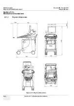
Страница 246: ...E8 VOLUSON E6 DIRECTION KTD102576 REVISION 7 DRAFT AUGUST 23 2012 SERVICE MANUAL 5 62 Section 5 11 Mechanical Descriptions Section 5 11 Mechanical Descriptions 5 11 1 Physical Dimensions Figure 5 35 P...

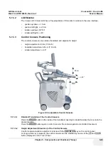
Страница 247: ...ustment 20 cm 7 8 inch translation adjustment 20 cm 7 8 inch rotation adjustment 40 5 11 3 1 Rotation Translation of the Control Console Press the BRAKE button in the inside of the handlebar opening t...

Страница 248: ...E6 scanner Air holes in the RTP secondary power supply allow the air to pass through the 3 fans between RTP and Beamformer suck in the air and spread it through the beamformer and around the RFI board...

Страница 249: ...on E8 Voluson E6 scanner requires permission and customer input to run diagnostics 5 13 2 1 Local Access 1 If not already in read mode FREEZE the image 2 Press the UTILITIES key on the control panel a...

Страница 250: ...cation OLC to quickly assist the customer NOTE Visual information about the network status is shown in the status area on the bottom of the screen 4 If you select Cancel Disruptive Mode and VCO is tur...

Страница 251: ...e There are different possibilities to access the Common Service Desktop and its available features 1 Local Access via System Setup Administration SERVICE page 2 Remote Access requires customers permi...

Страница 252: ...5 14 3 Diagnostics The Diagnostic page uses a web controlled user interface to provide access to common service components and perform diagnostics Non Interactive The tests are performed without the...

Страница 253: ...and Functions Theory 5 69 5 14 4 Image Quality In the Image Quality page you can verify image quality NOTE This page is not populated in this version 5 14 5 Calibration In the Calibration page you can...

Страница 254: ...iguration page you can view and modify different device informations and configurations in the InsiteExC Agent Configuration option field Figure 5 45 Common Service Desktop Configuration NOTICE NOTICE...

Страница 255: ...stem in addition to various other tools 5 14 8 Replacement In the Replacement page Hardware parts and their versions are displayed 5 14 9 PM In the PM page information about planned proactive and prev...

Страница 256: ...click the SERVICE tab 4 Enter the password SHE and click the ACCEPT button to display the Service Tools window 5 15 3 1 Auto Tester Autotester is a log function of customer activities It records all u...

Страница 257: ...r DICOM transfers both directions 5 15 3 4 Activate Deactivate Service This offers GE technicians the possibility to view the entire customer s desktop and operation system Using VCO Virtual Console O...

Страница 258: ...the Application presets does not match the Application Software version it is probably that there are adverse affects on image quality e g after reloading an old Full Backup Select the LOAD APPLICATIO...

Страница 259: ...able as soon as the Boot Screen appears 5 16 1 1 Voluson The System will boot up in windows The Ultrasound Application is started For details refer to Section 3 6 2 3 During a normal boot you may obse...

Страница 260: ...as the Boot Screen appears see Figure 5 52 on page 5 75 press the PG DN Arrow down key on the keyboard until the Rollback item is highlighted then press ENTER 3 When the following WARNING message app...

Страница 261: ...about 2 5 hours If there are errors they will be listed NOTE If after one cycle about 2 5 hours no error messages are listed it can be assumed that the Back End Processor including power supply is wo...

Страница 262: ...GE HEALTHCARERAFT VOLUSON E8 VOLUSON E6 DIRECTION KTD102576 REVISION 7 DRAFT AUGUST 23 2012 SERVICE MANUAL 5 78 Section 5 16 Boot Screen Functions This page was intentionally left blank...

Страница 263: ...tents of this Chapter 6 1 Overview 6 1 6 2 Regulatory 6 1 6 3 LCD Monitor Adjustment 6 1 6 4 Monitor Arm Adjustment 6 6 6 5 Control Console Positioning 6 7 6 6 Modification of Keyboard Layout 6 9 Sect...

Страница 264: ...alues will be lost after loss of power Figure 6 1 Monitor Menu e g BT12 Figure 6 2 Default Monitor Settings NOTICE NOTICE It is impossible to re program default monitor settings BT Version Readjustmen...

Страница 265: ...ation room light conditions Typically values depending on the operator 1 Press the UTILITIES key on the control panel 2 Touch the MONITOR button to display the Monitor Menu on the screen see Figure 6...

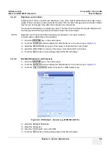
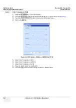
Страница 266: ...anel 2 Touch the MONITOR button to display the Monitor Menu on the screen see Figure 6 1 3 Touch the OSD CONTROLS button to invoke the OSD Adjust menu 4 Click on the RGB tab 5 Adjust Color Temperature...

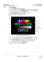
Страница 267: ...R TEST button in the Service Tools menu 6 Confirm the Monitor Test message with YES The Monitor Test main menu appears on the screen 7 Select the Color calibration icon and press the right left trackb...

Страница 268: ...6 4 Monitor Arm Adjustment 1 If the outdated monitor arm KTZ154817 with mounted monitor moves self acting retighten the Allen screw on the upper part of the monitor arm 2 If the monitor tilts downwar...

Страница 269: ...6 7 Buttons for Control Console Adjustment CAUTION CAUTION The system should NOT be moved with the Control Console UI extended DO NOT put your hand between the control console and the Main system whe...

Страница 270: ...TE Shipping the Voluson E8 Voluson E6 ultrasound system in its original packaging is only possible when the system is lowered to its minimum height with monitor flapped and locked down and when the co...

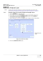
Страница 271: ...ive language keys on page 8 21 6 6 1 Setup the Voluson E8 Voluson E6 Keyboard Language Layout 1 Press the UTILITIES key on the control panel 2 In the Utilities menu touch SYSTEM SETUP to invoke the se...

Страница 272: ...input language from the drop down menu see Figure 6 10 The corresponding keyboard layout is changed automatically 8 Click on APPLY and then close the window with OK 9 Close the Service page with the S...

Страница 273: ...diagnostics or to be sent back to the manufacturer for analysis There are different options to acquire this data that would give different results 7 1 3 Contents in this Chapter 7 1 Overview 7 1 7 2 C...

Страница 274: ...reen select ADMINISTRATION and then click the SYSTEM INFO tab The following information is necessary in order to properly analyze data or images being reported as a malfunction or being returned to th...

Страница 275: ...age may be slightly different Figure 7 1 System Setup Administration SYSTEM INFO page e g BT13 Serial number Application Software Backup File Name System Type Date of Factory Settings Hardware ID e g...

Страница 276: ...Disconnect all probes 6 Click the HW CONFIGURATION DETECTION button see Figure 7 1 on page 7 3 on the bottom of the page to start board detection The system is restarted automatically after the check...

Страница 277: ...nd then click the SERVICE tab 4 Enter the password SHE and click the ACCEPT button to display the Service Tools window 5 Click the RFS button and fill out the displayed form Enter detailed Problem des...

Страница 278: ...t d A request confirmation screen is displayed 8 Write down and keep the Reference Number for follow up procedures then click OK NOTE If the service platform is not configured an Error message is disp...

Страница 279: ...LY This function is not intended for the user Ctrl Alt D Factory use ONLY This function is not intended for the user Shift F11 start remote socket control Ctrl H shortcuts list see Figure 7 7 above Al...

Страница 280: ...power 7 3 1 1 RTN Primary Power Supply AC AC Turn on mains switch and check green LED inside RTN 7 3 1 2 RTP Secondary Power Supply AC DC Power on the system and check the green LED inside the RTP NOT...

Страница 281: ...isting snapshots at destination HDD C creates one snapshot Alt D bmp Full Backup of the System state fullbackup fb1 saved on D export by pressing the ALT D key on the alpha numeric keyboard 7 4 1 Capt...

Страница 282: ...hen the problem should be investigated by R D It is not intended to replace or enhance the existing Full Backup functionality Data can be stored on the hard disk D export fullbackup fb1 or you can exp...

Страница 283: ...the ACCEPT button to display the Service Tools window 5 Click on the EXPORT SYSTEM DATA button to Full Backup the System State This includes dump files see Section 7 4 2 2 1 and text files full Servi...

Страница 284: ...mage 2 Move the cursor to the GE icon and press the right trackball key right click 3 Select Connect Clinical Lifeline see Figure 7 14 below This activates Disruptive Mode and VCO for the application...

Страница 285: ...nician requests remote access to your Voluson E8 Voluson E6 scanner following InSite Notification appears on the systems s creen 1 Enable Disruptive Mode feature by confirming YES NOTE If the customer...

Страница 286: ...e Desktop CSD is started the Service Home Page appears NOTE As described in Chapter 5 Common Service Desktop CSD on page 5 67 the service platform uses a web based user interface UI to provide access...

Страница 287: ...d stated mandatory fields 4 Enter Proxy Server Address and Proxy Server Port 5 Click the SUBMIT CHANGES button and then close the service page NOTICE NOTICE If a Proxy server is available the informat...

Страница 288: ...ey on the control panel 2 In the Utilities menu touch SYSTEM SETUP to invoke the setup desktop on the screen 3 On the left side of the screen select ADMINISTRATION and then click the SERVICE tab The p...

Страница 289: ...te the Auto Tester program by clicking the Record icon on the displayed screen 9 Start scanning You can scan normally and everything will be recorded to the program up to several hours NOTE It is impo...

Страница 290: ...imitation of the Auto Tester The following information will not be recorded Depending on the moment the Auto Tester is activated this must be provided by the customer or the field engineer Which probe...

Страница 291: ...t to RTV DVI In d Monitor e Kontron Dual Core BT10 only RTV 2 Connect the Mains Power cable and mount the pull out protection see Figure 4 4 on page 4 4 3 Connect the Power Cable to an appropriate mai...

Страница 292: ...um Configuration to Boot Scan 7 7 1 Minimum Configuration to Scan cont d Figure 7 23 cable minimum configuration BT10 Figure 7 24 cable minimum configuration BT12 BT13 a c b DFI Dual core version KONT...

Страница 293: ...E8 Voluson E6 troubleshooting trees and instructions shown in the sub sections 7 8 1 System does not boot up 7 22 7 8 2 Noise disturbs the Image 7 23 7 8 3 Trackball Impaired Sensitivity 7 24 7 8 4 Pr...

Страница 294: ...Cord is connected to Mains Power Switch is turned on on the backside of the system Is Standby Switch orange Press Standby Switch till it changes to green System starts booting Press Standby Switch for...

Страница 295: ...AL Chapter 7 Diagnostics Troubleshooting 7 23 7 8 2 Noise disturbs the Image Figure 7 26 Noise disturbs the Image Troubleshooting Noise is shown in Image YES NO Is there any electrical devices that af...

Страница 296: ...ckball 1 Remove the trackball fixating ring by turning it counterclockwise 2 Affix an adhesive tape to take out the trackball and then clean it with soft tissue 3 Mount the fixing ring by turning it c...

Страница 297: ...ter loaded with paper Load paper by using the correct format Check paper size small large etc Check paper tray to fit with the used paper format Is printing media ink cartridge etc empty Depending on...

Страница 298: ...he monitor Eliminate the sources and then degauss the monitor Screen image is not centered or sized properly Adjust the picture location picture size picture rotation or pincushion distortion Some vid...

Страница 299: ...Enter Patient Archive by pressing the PATIENT ID key on the control panel 3 On the left side of the screen select ARCHIVE as shown in Figure 7 29 ABOVE 4 If not already selected choose Local Archive f...

Страница 300: ...name d Select any Voluson Format 4dv from the pop up menu e Click the SAVE button After successful export perform an import of images 1 On the left side of the screen select IMPORT 2 Choose DVD CD re...

Страница 301: ...display e g of Carotid 6 Touch the STOP button to stop recording 7 Press the DVD VCR key on the control panel once to display the remote control menu again 8 Touch the PLAY button to play back the rec...

Страница 302: ...stem to IP address on PC If OK hardware connection inside the system is OK 7 8 7 2 GE remote service connection The customer gets visual information about GE remote service status shown in the status...

Страница 303: ...Transfer Import The Open File window appears 3 Select Drive in the Look In pull down menu 4 In the File of type field change file type to V730 Format v730 mdb 5 Browse for the folder where SonoView B...

Страница 304: ...cause crashes and lose valuable data press Ok and stop it before removing it next time AcquMode incorrect BBC_Wnd pointer restart the system Another drive is already assigned to xx that is no DVD CD...

Страница 305: ...ters failed Action restart the system If after restart not ok then call technical support restart the system bCP_ConvertParameters failed Action restart the system If after restart not ok then call te...

Страница 306: ...not ok call technical support use a new DVD CD R to write data to DVD CD Can t load 830_IntensityMeasureData dll restart the system Can t open restart the system Can t open patterndat bin Action resta...

Страница 307: ...DistanceFocusReferenceBF_ToProbeSurface out of valid range Action restart the system restart the system Delete error Backup data could not be deleted check storage destination of Full Backup e g DVD C...

Страница 308: ...in ProbeTxFocusData Action Please contact technical support Please contact technical support Error in Select Tx channel for B mode restart the system Error in Select Tx channel for C mode restart the...

Страница 309: ...eCF operator handed over argument is not of same type dynamic cast failed restart the system GeoDescriptionMotion Constructor unknown mode Parameter handed over restart the system GeoDescriptionMotion...

Страница 310: ...ll technical support restart the system iSetVideoSource eVideoExtern function fails restart the system iSetVideoSource eVideoIntern function fails Action reboot the system reboot the system iSetVideoS...

Страница 311: ...tings available use Edit Settings to set the Default Settings select a printer No disc or device not ready insert disk if fails again reboot and try again with another disk No DVD in drive Put DVD int...

Страница 312: ...EEPROM Datamodel not implemeted yet On Attempt to read Probe ID from an invalid probe connector Action restart system restart the system Probe ID valid but Flexible EEPROM Datamodel not implemeted yet...

Страница 313: ...AllListener called within Transaction restart the system RepresentationManager removeListener called within Transaction restart the system RepresentationManager vClear called within Transaction restar...

Страница 314: ...k bStart ECGInterface failed restart the system RT_MColorFilterBlock Memory allocation failed Action restart the system If after restart not ok then call technical support restart the system RT_MColor...

Страница 315: ...after restart not ok then call technical support restart the system RT_RFProcessingBlockColor vCheckRFDataSizeAndUpdateBuffers Memory allocation failed Action restart the system If after restart not...

Страница 316: ...start the system and try again The Registry not closed Action close registry restart try again restart the system The System detected a problem with your harddisk Please do not reboot or shut down the...

Страница 317: ...or B Connect another probe Unhandled Probe EEPROM data type on right probe connector C Connect another probe Unhandled Probe EEPROM data type on upper left probe connector CW Connect another probe Uni...

Страница 318: ...call technical support use a new CDR Write Protected cassette Remove cassette from VCR and put writeable cassette into drive of VCR Remove cassette from VCR and put writeable cassette into drive of VC...

Страница 319: ...nts from Preparations to Installation Procedures WARNING WARNING WARNING No covers or panels should be removed from the system high voltage risk Service and repairs must only be performed by authorize...

Страница 320: ...e VGA Image Video Resizer 8 26 8 17 4 Mounting Replacing the 19 LCD Secondary Patient Monitor 8 29 8 1 3 Returning Shipping System Probes and Repair Parts When returning or shipping the Voluson E8 Vol...

Страница 321: ...ic Permanent key in OKOS Please contact your local distributor or GE service representative to get the necessary key NOTE It is NOT necessary to save Full System Configuration Full Backup prior to the...

Страница 322: ...control panel 2 In the Utilities menu touch SYSTEM SETUP to invoke the setup desktop on the screen 3 On the left side of the screen select ADMINISTRATION and then click the SYSTEM INFO tab to see whi...

Страница 323: ...led software has to be upgraded to a newer version and the system DVD being used is SW 9 0 3 or higher a new software specific Permanent key is required Please contact your local distributor or GE ser...

Страница 324: ...ne disconnect all external USB devices except DVD CD R RW drive 3 Insert the System DVD into the drive 4 Restart the system Turn system OFF and then back ON 5 After system restart press the UTILITIES...

Страница 325: ...then it reboots into LINUX A silent Rollback image from C is stored on R After executing all LINUX commands the system reboots again NOTE If the currently installed software has to be upgraded to a n...

Страница 326: ...stem Software Installation Upgrade Procedure 8 2 5 System Software Installation Procedure FMI from DVD cont d 12 Check disk is performed automatically restart 13 3 dots one after the other appear on t...

Страница 327: ...placement Procedures 8 9 8 2 5 System Software Installation Procedure FMI from DVD cont d 14 Booting auto 15 Updating will take some time 16 Please wait until all processes are finished 100 percent co...

Страница 328: ...hut down the system then boot up again 21 Reconnect the external devices install all the printers and adjust the printer settings as described in Section 3 7 Printer Installation on page 3 36 22 Check...

Страница 329: ...oftware version 8 Disconnect all probes and then click the button at the bottom of the SYSTEM INFO page to start Hardware configuration detection see Figure 8 14 above 9 Perform basic functional check...

Страница 330: ...y curves and complete System settings such as language time date format etc Measure Configuration user specific measure setup settings Patient Archive database containing patient demographic data and...

Страница 331: ...D Heart SonoVCAD Heart SonoAVC Sono Automated Volume Count SonoAVC Sono Automated Volume Count Expert Upgrade Voluson E8 Voluson E8 Expert Anatomical M Mode Anatomical M Mode Scan Assistant Scan Assis...

Страница 332: ...Spatio Temporal Image Correlation SonoVCAD Labor SonoVCAD Labor Contrast Coded Contrast Imaging Contrast Coded Contrast Imaging SonoAVC Sono Automated Volume Count SonoVCAD Heart Expert Upgrade Voluso...

Страница 333: ...be checked 4 Click the SAVE EXIT button NOTE After activating a key code restart turn off and on the Voluson E8 Voluson E6 system Figure 8 15 System Setup Administration OPTIONS page e g Voluson E8 E...

Страница 334: ...over 8 8 1 1 Manpower One person 1 minute 8 8 1 2 Tools none 8 8 1 3 Preparations 1 Power Off Shutdown the system as described in Section 4 3 2 on page 4 4 8 8 1 4 Footrest Cover Removal Procedure 1 F...

Страница 335: ...son 1 minute 8 8 2 2 Tools none NOTE The Voluson Cover is fixed by magnets only 8 8 2 3 Preparations 1 Power Off Shutdown the system as described in Section 4 3 2 on page 4 4 8 8 2 4 Voluson Cover Rem...

Страница 336: ...older 8 9 1 Manpower One person 3 minutes 8 9 2 Tools Phillips screwdriver PH1 and PH2 8 9 3 Cable Holder Removal Procedure 1 Loosen the 2 screws below the control console and then remove the cable ho...

Страница 337: ...ction 8 10 Replacement of the Probe Holder Kit 8 10 1 Manpower One person 1 minute 8 10 2 Tools None 8 10 3 Probe Holder Kit Removal Procedure 1 Pull out the elastic probe holder to be replaced 8 10 4...

Страница 338: ...the probe holder for endocavity probes 8 11 4 Probe Holder endocavity Installation Procedure 1 Place the new probe holder at its original position and fasten it with the 4 screws Section 8 12 Replace...

Страница 339: ...is completely loosened from its base see Figure 8 23 below 3 Remove the key cap 8 13 5 Key Caps Installation Procedure 1 Carefully place the appropriate key cap in position on the keyboard taking care...

Страница 340: ...ots depend on installed Console RTU The Console version is shown in the System Info page see Figure 7 1 on page 7 3 8 14 1 Manpower One person 5 minutes 8 14 2 Tools none poss small sized slotted scre...

Страница 341: ...1 Manpower One person approx 1 minute cap 8 15 1 2 Tools small sized slotted screwdriver or tweezers 8 15 1 3 Circle Key Caps Replacement Procedure 1 By means of a small slotted screwdriver carefully...

Страница 342: ...n Lock is only used if the outdated monitor arm KTZ154817 is mounted on the Voluson system 8 16 1 Manpower One person 2 minutes 8 16 2 Tools Phillips screwdriver PH1 and PH2 8 16 3 Monitor Transportat...

Страница 343: ...r date 8 17 1 Manpower One person 30 60 minutes depending on auxiliary device 8 17 2 Tools slotted screwdriver How to replace optional peripherals or how to mount them at a later date 8 17 3 Mounting...

Страница 344: ...below NOTICE NOTICE The VGA Image Video Resizer is required whenever the used Secondary Patient Monitor has a different screen resolution than the Voluson E8 Voluson E6 system CAUTION CAUTION A Second...

Страница 345: ...nd plug the other end into the Power Supply s input socket see Figure 8 30 below 7 Connect your Secondary Monitor to the Image Resizer Box at its PC HD OUTPUT Connector 8 After the installation Power...

Страница 346: ...e Resizer Box see Figure 8 33 below 7 Connect the DC Power Output from the Power Supply to the DC Power Input at the Resizer Box 8 Connect your Secondary Monitor to the Image Resizer Box at its PC HD...

Страница 347: ...nded for diagnostic use It is an additional device used to allow the patient to watch the proceedings Figure 8 34 Wall Mount kit for 19 LCD Secondary Monitor NOTICE NOTICE Take your time to think abou...

Страница 348: ...4 screws see left image in Figure 8 36 below 4 Place the monitor bracket mount and fix it with 4 screws see right image Figure 8 36 above 5 Put the mounting plate on top of the monitor bracket mount a...

Страница 349: ...e 1 Put the hook of the monitor bracket mount in the indention of the wall bracket mount 2 Rotate the locking lever until it is vertical Now the monitor is mounted and secure NOTE To rotate the lever...

Страница 350: ...he power inlet block with a small screwdriver and remove the fuse holder 3 By turning the fuse holder you can select 115V or 230V Consider that changing the input voltage also requires to change the f...

Страница 351: ...the viewing window see Figure 8 44 below 5 The output voltage must also be changed by the turn switch which is located on the right side For that purpose use an appropriate screwdriver and make sure...

Страница 352: ...tor with the picture on the Voluson E8 Voluson E6 monitor NOTE If you need to change the configuration of the newly installed monitor please refer to the manual of the Secondary Monitor which is enclo...

Страница 353: ...echanical Hardware Parts Covers 9 4 9 5 User Interface 9 6 9 6 Monitor Monitor Replacement Parts 9 11 9 7 Main Power Modules 9 12 9 8 Main Board Module 9 13 9 8 1 FrontEnd US Part Components 9 13 9 8...

Страница 354: ...tock part GBF Beamformer Module HDD Hard Disk Drive HVPS High Voltage Power Supply Int Internal I O Input Output LCD Liquid Crystal Display LVPS Low Voltage Power Supply MAN ECG Module PCI Peripheral...

Страница 355: ...Main Board Module FrontEnd US Part Components FrontEnd US Part Components cont d BackEnd PC Part Components Table 9 9 on page 9 13 Table 9 10 on page 9 15 Table 9 11 on page 9 17 Ultrasound FrontEnd C...

Страница 356: ...Back Top Cover for Voluson E8 Voluson E6 1 N Y 103 Voluson Cover KTZ134696 Voluson Cover for Voluson E8 Voluson E6 1 Y Y 104 Footrest Cover KTZ134633 Footrest Cover for Voluson E8 Voluson E6 1 Y Y 10...

Страница 357: ...Z196224 right Side Cover incl Door for Probe cables 1 N Y 113 Top Cover KTZ134643 Top Cover for Voluson E8 Voluson E6 1 N Y 114 Labels doors User Interface KTZ280100 Labels for doors and User Interfac...

Страница 358: ...E6 DIRECTION KTD102576 REVISION 7 DRAFT AUGUST 23 2012 SERVICE MANUAL 9 6 Section 9 5 User Interface Section 9 5 User Interface Figure 9 4 User Interface 201 202 203 204 205 206 207 208 209 210 211 21...

Страница 359: ...ces with premounted brackets 10 Y Y 209 Caps for Hardkeys 2 R KTZ300424 all caps for hardkeys on RTU3 4 5 6 Console 1 Y Y 210 Function Key Set W KTZ280225 includes all caps for hardkeys on RTU50 Conso...

Страница 360: ...VE8 VE6 KTZ280252 Set includes DVD R W Writer internal Data cable IDE and Distribution Board USB Hub RTH5 1 N Y 225 DVR Drive KTZ302198 internal DVR Drive DVD Drive with an integrated Digital Video R...

Страница 361: ...VOLUSON E6 DIRECTION KTD102576 REVISION 7 DRAFT AUGUST 23 2012 SERVICE MANUAL Chapter 9 Renewal Parts 9 9 Section 9 5 User Interface cont d Figure 9 6 User Interface cont d 230 231 232 235 237 238 23...

Страница 362: ...ey cap kit is needed see Table 9 12 on page 9 18 1 N Y 234 Console Main Board right W KTZ280234 Console Main Board right 1 N Y 235 A N Keyboard W KTZ280233 Alphanumeric Keyboard English 1 N Y 236 Cons...

Страница 363: ...Monitor Arm 19 incl cables and cover KTZ301103 Holder for Voluson E8 Voluson E6 Monitor premounted monitor cables and monitor back cover 1 N Y 305 Monitor Arm 2 incl cables and cover KTZ280247 Holder...

Страница 364: ...Primary Power Supply RTN 1 25A 1 6A 10A and 15A 10 pcs each 40 N Y 403 RTP6c P5 Secondary Power Supply KTZ280174 Secondary Power Supply Module RTP 1 N Y 404 RTP60 P5 Secondary Power Supply KTZ280097...

Страница 365: ...igure 7 1 on page 7 3 Figure 9 9 FrontEnd US Part Components Table 9 9 FrontEnd US Part Components Item Part Name Part Number Description Qty CRU FRU 501 Fan Tray 3 fan KTZ154770 Fan Tray 3 fan FrontE...

Страница 366: ...E8 VOLUSON E6 DIRECTION KTD102576 REVISION 7 DRAFT AUGUST 23 2012 SERVICE MANUAL 9 14 Section 9 8 Main Board Module 9 8 1 FrontEnd US Part Components cont d Figure 9 10 FrontEnd US Part cont d 512 51...

Страница 367: ...obe Control Board RTF and Beamformer Motherboard RTM without any Sub boards 1 N Y 513 GBF80 Beamformer Module without Sub boards KTZ280090 Beamformer Assembly including Probe Control Board RTF and Bea...

Страница 368: ...SON E6 DIRECTION KTD102576 REVISION 7 DRAFT AUGUST 23 2012 SERVICE MANUAL 9 16 Section 9 8 Main Board Module 9 8 2 BackEnd PC Part Components Figure 9 11 BackEnd PC Part Components 571 572 573 574 579...

Страница 369: ...Disk Drive HDD BT12 BT13 KTZ302446 Hard disk drive SATA 500Gbyte Western Digital or Hitachi System Boot DVD see Table 9 12 is required 1 N Y 578 Fan Set 2 fan for PC BackEnd KTZ134698 Fan for PC box...

Страница 370: ...tem Manuals etc N N 606 Upgrade Kit Voluson E8 Voluson E8 Expert BT08 to BT09 H48671PK BT09 Upgrade kit incl new Hardware components new BackEnd Processor kit System DVD System Manuals etc N N 607 Upg...

Страница 371: ...ation H48671YB encrypted Software Option string password N N 628 STIC Basic BT10 Spatio Temporal Image Correlation H48681FS encrypted Software Option string password N N 629 B Flow BT09 H48671YC encry...

Страница 372: ...Kit Finnish KTZ280012 H48651SC kit includes special native language keys Y 656 Key Cap Kit Finnish W KTZ280241 H48681WN kit includes special native language keys Y 657 Key Cap Kit Spanish KTZ280011 H4...

Страница 373: ...ber Description Qty CRU FRU 701 SATA Data Cable for HD Drive KTZ300244 SATA Data Cable for HD Drive 1 N Y 702 PCI E Connection Cable BEP RFI KTZ220428 PCI E Connection Cable from BackEnd to RFI board...

Страница 374: ...nd DVI Video Cable 1 N Y 706 Monitor Cable Set 2 cables KTZ280164 Monitor Cable Set Power Cable and DVI Video Cable 1 N Y 707 Monitor Cable Set 2 2 cables KTZ280251 Monitor Cable Set Power Cable and D...

Страница 375: ...wer Cord United Kingdom 240V used at Mains Input Connector C20 16A type 1 Y Y 711 Power Cord USA Hosp grade KTZ212402 Power Cord USA Hospital Grade used at Mains Input Connector C20 16A type 1 Y Y 712...

Страница 376: ...Power Cord Australia used at Mains Input Connector C14 10A type Y Y 716 Power Cord India KTZ220387 Power Cord India used at Mains Input Connector C14 10A type Y Y 717 Power Cord United Kingdom KTZ2204...

Страница 377: ...KTZ220479 Power Cord Israel used at Mains Input Connector C14 10A type Y Y 721 Power Cord Switzerland KTZ220480 Power Cord Switzerland used at Mains Input Connector C14 10A type Y Y 722 Power Cord De...

Страница 378: ...tal Visual Interface from DVI Output at ADD On or Graphic card to RTV KTZ208574 Cable DVI Digital Visual Interface from DVI Output at ADD On or Graphic card to RTV 1 N Y 726 Console Cable KTZ220876 Co...

Страница 379: ...Cable KTZ212125 USB Cable for Printers 1m 1 N Y 731 USB to PC Motherboard BT09 only KTZ207029 Set contains two parts Not to be used at Voluson E8 Voluson E6 systems 1 N Y USB for PC Slot Connector on...

Страница 380: ...internal 1 N Y 733 Adapter S Video RCA Jack Cinch KTZ196334 Adapter S Video RCA Jack Cinch to be used in combination with GES15 1 N Y 734 RTP ATX Adapter KTZ220899 ATX Adapter between RTP Secondary P...

Страница 381: ...rness KTZ280179 Harness Grounding Console V Rec OUT Monitor DVI USB UI and USB Hub cable connector plate fourfold distributer cable cable tube tie wraps etc N Y 737 2nd HDD Power Cable KTZ280126 S ATA...

Страница 382: ...rations may not correspond to the actual product Figure 9 12 Optional Peripherals and Accessories Recording Tools Table 9 14 Optional Peripherals and Accessories Recording Tools Item Part Name Part Nu...

Страница 383: ...H48651ML Digital B W Video Printer USB Port N Y 812 Digital B W Video Printer Mitsubishi P95D KTZ302617 H48681TH Digital B W Video Printer USB Port N Y 813 Digital Color Printer e g Sony UP D25MD KTZ2...

Страница 384: ...olation Box replaces PRJ1 network isolation N Y 822 USB Stick 512MB 2411544 H48651TB USB Flash Memory Stick 512 MB Y Y 823 USB RS232 Connection kit PRY KTZ195858 H46681S Converter from USB to RS 232 S...

Страница 385: ...E6 DIRECTION KTD102576 REVISION 7 DRAFT AUGUST 23 2012 SERVICE MANUAL Chapter 9 Renewal Parts 9 33 9 11 4 Optional Equipment Figure 9 15 Optional Peripherals and Accessories Optional Equipment 832 83...

Страница 386: ...tor power cable fuses documentation etc N 834 Isolation Transformer KTZ220714 Isolation Transformer without cables etc Y Y 835 Fuses for Isolation Transformer KTZ196333 Fuses for Isolation Transformer...

Страница 387: ...671RK KTD102647 Basic User Manual Norwegian H48671TB KTD101720 H48671RL KTD102648 Basic User Manual Polish H48671TC KTD101721 H48671RM KTD102649 Basic User Manual Russian H48671TD KTD101722 H48671RN K...

Страница 388: ...User Manual Norwegian H48681CR H48681EC Basic User Manual Polish H48681CS H48681ED Basic User Manual Russian H48681CT H48681EE Basic User Manual Swedish H48681CW H48681EF Basic User Manual Turkish H48...

Страница 389: ...Basic User Manual Norwegian H48681MZ H48681PG Basic User Manual Polish H48681NA H48681PH Basic User Manual Russian H48681NB H48681PJ Basic User Manual Swedish H48681NC H48681PK Basic User Manual Turk...

Страница 390: ...H48691AX Basic User Manual Norwegian H48691CS H48691AY Basic User Manual Polish H48691CT H48691AZ Basic User Manual Russian H48691CU H48691BA Basic User Manual Swedish H48691CW H48691BB Basic User Ma...

Страница 391: ...pter 9 Renewal Parts 9 39 Section 9 13 Probes Replacement parts described in the sub sections 9 13 1 2D Probes Curved Array Transducers 9 40 9 13 2 2D Probes Linear Array Transducers 9 41 9 13 3 2D Pr...

Страница 392: ...Elements 5 rows Applications Abdominal Obstetrics Gynecology Pediatrics Y Y 902 AB2 7 D KTZ157022 H48651MW broadband curved array transducer 2 0 8 0 MHz 192 Elements Applications Abdominal Obstetrics...

Страница 393: ...s Peripheral Vascular Pediatrics Orthopedics Y Y 911 11L D KTZ157048 H40432LN broadband linear array transducer 4 0 10 0 MHz 192 Elements electronically steerable Applications Small Parts Peripheral V...

Страница 394: ...array transducer 4 0 10 0 MHz 128 Elements Applications Abdominal Cardiology Pediatrics Neonatology Y Y 921 3S D KTZ280049 H48661LG broadband phased array transducer 1 0 3 0 MHz 64 Elements Applicati...

Страница 395: ...OLUSON E6 DIRECTION KTD102576 REVISION 7 DRAFT AUGUST 23 2012 SERVICE MANUAL Chapter 9 Renewal Parts 9 43 9 13 4 Real Time 4D Volume Probes Figure 9 19 Real Time 4D Volume Probes 937 938 939 934 942 9...

Страница 396: ...ments Applications Small Parts Periph Vascular Pediatrics Urology Orthopedics Y Y 936 RAM3 8 KTZ157039 1 5D Abdominal Matrix Array Real time 4D broadband electronic transducer 2 0 6 0 MHz 192 Elements...

Страница 397: ...bes Item Part Name Part Number Description Qty CRU FRU 940 P2D KTZ280051 H4830JE Continuous Wave CW Doppler pencil probe with a center frequency of 2 0 MHz no B image 2 Elements Applications Cardiolog...

Страница 398: ...eter 1 8 mm N 953 RIC Single angle bracket H48681GF disposable Biopsy needle guide for probe RIC5 9 D RIC6 12 D needle diameter 16 18GA gauge 1 2 1 6 mm N 954 PEC64 H46721B reusable Biopsy needle guid...

Страница 399: ...dle diameter 1 mm 1 4 mm 2 2 mm N 963 RSP Single angle bracket H46701AD Non Sterile Single Angle Bracket needle guide for probe RSP6 16 D needle diameter 8 5FR 14 23GA gauge 0 6 mm 2 1 mm N 964 PEC76...

Страница 400: ...uge 0 6 mm 2 1 mm N 973 C4 8 D Biopsy guide H48681AT Non Sterile Multi Angle Bracket needle guide for probe C4 8 D needle diameter 8 5FR 14 23GA gauge 0 6 mm 2 1 mm N 974 12L RS Multi angle bracket H4...

Страница 401: ...s before performing a task 10 1 3 Contents in this Chapter 10 1 Overview 10 1 10 2 Why do Maintenance 10 2 10 3 Maintenance Task Schedule 10 2 10 4 Tools Required 10 5 10 5 System Maintenance 10 6 10...

Страница 402: ...and maintained on the site Your GE service representative can help you with establishing performing and maintaining records for a quality assurance program Please contact us for coverage information...

Страница 403: ...eful not to get the cloth too wet so that moisture does not enter the entire system Mechanical parts Clean and inspect the mechanical function of wheels casters brakes and swivel locks as well as side...

Страница 404: ...by your facilities QA program Measurement Accuracy Checks Also after corrective maintenance or as required by your facilities QA program Probe Phantom Checks Check Gain and TGC changes vary the focus...

Страница 405: ...370 Kit includes anti static mat wrist strap and cables for 200 to 240 V system 3M 2204 Large adjustable wrist strap 3M 2214 Small adjustable wrist strap 3M 3051 conductive ground cord Anti Static Vac...

Страница 406: ...he top of the EQC Ultrasound Equipment Quality Check form see page 10 25 Record all probes and system options 3 Power up Turn the system power on and verify that all fans and peripherals turn on Watch...

Страница 407: ...e of operation 5 Doppler Modes Verify basic Doppler Mode operation PW and CW if available Check the basic system controls that affect this mode of operation 6 3D Mode Verify basic 3D Mode operation Ch...

Страница 408: ...d covers if necessary 3 Color Deskjet Bluetooth Printer Verify hardcopy output of the Deskjet Bluetooth printer Clean heads and covers if necessary 4 VCR Verify record playback capabilities of the VCR...

Страница 409: ...heel locks and swivel locks for proper operation 7 Cables Connectors Check all internal cable harnesses and connectors for wear and secure connector seating Pay special attention to footswitch assembl...

Страница 410: ...on 1 Probes Thoroughly check the system probe connectors and remove dust from inside the connector sockets if necessary Visually check for bent damaged or missing pins 2 Probe Holder Clean probe holde...

Страница 411: ...ocess Inadequate handling may lead to dead elements shocked head mechanics etc The RIC Holder especially developed for RIC Real time 4D endocavity probes guarantees that the sensitive probe head does...

Страница 412: ...d strain relief at each end Inspect the transducer enclosure and lens for cracks holes and similar defects CAUTION Compare all safety test results with safety test results of previously performed safe...

Страница 413: ...ge test where mains supply voltage is applied to the part to determine the amount of current that will pass or sink to ground if a patient contacted mains voltage Table 10 10 Leakage Current Limits fo...

Страница 414: ...unction For ultrasound equipment this includes transducers and ECG leads Type BF Body Floating or non conductive ultrasound probes which are marked with the man in box BF symbol This includes all tran...

Страница 415: ...er and noting the combination of lights that are illuminated Any problems found should be reported to the hospital immediately and the receptacle should not be used NOTE No outlet tester can detect th...

Страница 416: ...ed AC wall outlet 3 Plug the black chassis cable into the meter s CHASSIS connector and attach the black chassis cable clamp to an exposed metal part of the Voluson E8 Voluson E6 system 4 Set the mete...

Страница 417: ...page 10 13 as applicable Record the highest reading of current When using the Microguard or a similar test instrument its power plug may be inserted into the wall outlet and the equipment under test i...

Страница 418: ...robe may vary by system Record all data in the Electrical safety tests log Table 10 15 Typical Data Format for Recording Chassis Source Leakage System Under Test ________________________ Date of Test...

Страница 419: ...le For each combination the operating controls such as the lead switch should be operated to find the worst case condition CAUTION CAUTION Equipment damage possibility Never switch the Polarity when t...

Страница 420: ...icable Record all data on the Inspection Certificate Table 10 17 Typical Data Format for Recording Patient Lead to Ground Leakage System Under Test ________________________ Date of Test ______________...

Страница 421: ...hest leakage current measured 10 7 7 1 Lead to Lead Leakage Test Record Table 10 18 shows a typical format for recording the patient lead to lead leakage current Measurements should be recorded from e...

Страница 422: ...ated patient lead sink leakage current Measurements should be recorded for the full lead combination under each set of test conditions specified in Table 10 10 on page 10 13 or Table 10 11 on page 10...

Страница 423: ...7 9 3 Generic Procedure on Probe Leakage Current The most common method of measuring probe leakage is to partly immerse the probe into a saline bath while the probe is connected to the ultrasound syst...

Страница 424: ...rmal from probe to probe Other variations will result from differences in line voltage and test lead placement The maximum allowable leakage current for body surface contact probe differs from inter c...

Страница 425: ...CTION 10 5 4 FUNCTIONAL CHECKS Item Complete Comments Item Complete Comments Input Power Monitor External I O Touch Panel Wheels and Brakes Keyboard Control Panel Movement B Mode Cables and Connectors...

Страница 426: ...librium connector Chassis Source Leakage Current Monitor housing Chassis Source Leakage Current Probe connector Patient Lead Source Leakage Lead to Ground Patient Lead Source Leakage Lead to Lead Pati...

Страница 427: ...Rollback 5 76 Voluson 5 75 Boot Up 3 31 4 2 C Cable Holder Replacement Procedures 8 18 Calculation Measurements Functional Checks 4 28 General remarks to perform 4 28 Caps for Hardkeys Replacement Pr...

Страница 428: ...47 Calculation Measurements 4 28 Cine Mode 4 23 Color Flow Modes 4 17 Control Panel 4 5 Doppler Modes 4 16 ECG Checkout 4 46 Generic Measurements 4 25 M Mode 4 14 Mechanical 4 47 Monitor Display 4 7...

Страница 429: ...ns Activation 8 13 Replacement Procedure 8 13 P Patient Archive Image Management Functional Checks 4 30 Peripherals Disk Drive Module GEM 5 59 Functional Checks 4 46 Physical Dimensions 2 5 Power Dist...

Страница 430: ...change Language 3 50 How to change Recorder Type 3 52 How to change the EUM Language 3 50 How to change Video Norm 3 52 How to configure Service Platform 3 52 How to enter Date and Time 3 50 How to e...

Страница 431: ......

Страница 432: ...2009 2012 General Electric Company GE Medical Systems a General Electric Company going to market as GE Healthcare GE Healthcare Austria GmbH Co OG Tiefenbach 15 A 4871 Zipf Austria www gehealthcare co...

Отзывы: