


GE Multilin
T60 Transformer Protection System
5-259
5 SETTINGS
5.7 CONTROL ELEMENTS
5
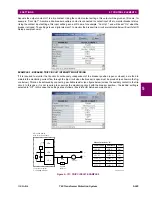
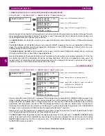
f) THERMAL OVERLOAD PROTECTION
PATH: SETTINGS
CONTROL ELEMENTS
MONITORING ELEMENTS
THERMAL OVERLOAD PROTECTION
THERMAL
PROTECTION 1(2)
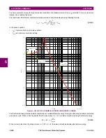
The thermal overload protection element corresponds to the IEC 255-8 standard and is used to detect thermal overload
conditions in protected power system elements. Choosing an appropriate time constant element can be used to protect dif-
ferent elements of the power system. The cold curve characteristic is applied when the previous averaged load current over
the last 5 cycles is less than 10% of the base current. If this current is greater or equal than 10% than the base current, then
the hot curve characteristic is applied.
The IEC255-8 cold curve is defined as follows:
(EQ 5.49)
The IEC255-8 hot curve is defined as follows:
(EQ 5.50)
In the above equations,
•
t
op
= time to operate.
•
τ
op
= thermal protection trip time constant.
•
I
= measured overload RMS current.
•
I
p
= measured load RMS current before overload occurs.
•
k
= IEC 255-8 k-factor applied to
I
B
, defining maximum permissible current above nominal current.
•
I
B
= protected element base (nominal) current.
THERMAL
PROTECTION 1
THERMAL PROTECTION 1
FUNCTION: Disabled
Range: Disabled, Enabled
MESSAGE
THERMAL PROTECTION 1
SOURCE: SRC1
Range: SRC 1, SRC 2, SRC 3, SRC 4, SRC 5, SRC 6
MESSAGE
THERMAL PROTECTION 1
BASE CURR: 0.80 pu
Range: 0.20 to 3.00 pu in steps of 0.01
MESSAGE
THERMAL PROTECTION 1
k FACTOR: 1.10
Range: 1.00 to 1.20 in steps of 0.05
MESSAGE
THERM PROT 1 TRIP
TIME CONST: 45 min.
Range: 0 to 1000 min. in steps of 1
MESSAGE
THERM PROT 1 RESET
TIME CONST: 45 min.
Range: 0 to 1000 min. in steps of 1
MESSAGE
THERM PROT 1 MINIM
RESET TIME: 20 min.
Range: 0 to 1000 min. in steps of 1
MESSAGE
THERM PROT 1 RESET:
Off
Range: FlexLogic™ operand
MESSAGE
THERM PROT 1 BLOCK:
Off
Range: FlexLogic™ operand
MESSAGE
THERMAL PROTECTION 1
TARGET: Self-reset
Range: Self-reset, Latched, Disabled
MESSAGE
THERMAL PROTECTION 1
EVENTS: Disabled
Range: Disabled, Enabled
t
op
τ
op
I
2
I
2
kI
B
(
)
2
–
--------------------------
ln
×
=
t
op
τ
op
I
2
I
p
2
–
I
2
kI
B
(
)
2
–
--------------------------
ln
×
=
Содержание UR T60
Страница 10: ...x T60 Transformer Protection System GE Multilin TABLE OF CONTENTS ...
Страница 14: ...xiv T60 Transformer Protection System GE Multilin 0 1 BATTERY DISPOSAL 0 BATTERY DISPOSAL 0 ...
Страница 34: ...1 20 T60 Transformer Protection System GE Multilin 1 5 USING THE RELAY 1 GETTING STARTED 1 ...
Страница 436: ...5 298 T60 Transformer Protection System GE Multilin 5 10 TESTING 5 SETTINGS 5 ...
Страница 492: ...8 18 T60 Transformer Protection System GE Multilin 8 3 ENERVISTA SECURITY MANAGEMENT SYSTEM 8 SECURITY 8 ...
Страница 510: ...9 18 T60 Transformer Protection System GE Multilin 9 6 COMMISSIONING TEST TABLES 9 COMMISSIONING 9 ...
Страница 678: ...C 30 T60 Transformer Protection System GE Multilin C 7 LOGICAL NODES APPENDIX C C ...
Страница 688: ...D 10 T60 Transformer Protection System GE Multilin D 1 IEC 60870 5 104 PROTOCOL APPENDIX D D ...
Страница 700: ...E 12 T60 Transformer Protection System GE Multilin E 2 DNP POINT LISTS APPENDIX E E ...


