


5-190
T60 Transformer Protection System
GE Multilin
5.6 GROUPED ELEMENTS
5 SETTINGS
5
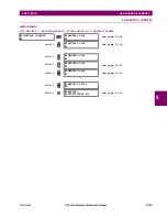
e) PHASE DIRECTIONAL OVERCURRENT
(ANSI 67P)
PATH: SETTINGS
GROUPED ELEMENTS
SETTING GROUP 1(6)
PHASE CURRENT
PHASE DIRECTIONAL 1
Phase directional target messages not used with the current version of the T60 relay. As a result, the target settings
are not applicable for the phase directional element.
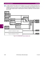
The phase directional elements (one for each of phases A, B, and C) determine the phase current flow direction for steady
state and fault conditions and can be used to control the operation of the phase overcurrent elements via the
BLOCK
inputs
of these elements.
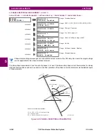
Figure 5–99: PHASE A DIRECTIONAL POLARIZATION
PHASE
DIRECTIONAL 1
PHASE DIR 1
FUNCTION: Disabled
Range: Disabled, Enabled
MESSAGE
PHASE DIR 1 SIGNAL
SOURCE: SRC 1
Range: SRC 1, SRC 2, SRC 3, SRC 4, SRC 5, SRC 6
MESSAGE
PHASE DIR 1 BLOCK:
Off
Range: FlexLogic™ operand
MESSAGE
PHASE DIR 1
ECA: 30
Range: 0 to 359° in steps of 1
MESSAGE
PHASE DIR POL V1
THRESHOLD: 0.700 pu
Range: 0.000 to 3.000 pu in steps of 0.001
MESSAGE
PHASE DIR 1 BLOCK
WHEN V MEM EXP: No
Range: No, Yes
MESSAGE
PHASE DIR 1
TARGET: Self-reset
Range: Self-reset, Latched, Disabled
MESSAGE
PHASE DIR 1
EVENTS: Disabled
Range: Disabled, Enabled
NOTE
827800A2.CDR
VBG
VCG
VAG(Faulted)
IA
ECA
set at 30°
ECA = Element Characteristic Angle at 30°
IA = operating current
Phasors for Phase A Polarization:
VPol = VBC
(1/_ECA) = polarizing voltage
×
Fault angle
set at 60° Lag
VAG (Unfaulted)
OUTPUT
S
0
1
VBC
VBC
VPol
+90°
–90°
Содержание UR T60
Страница 10: ...x T60 Transformer Protection System GE Multilin TABLE OF CONTENTS ...
Страница 14: ...xiv T60 Transformer Protection System GE Multilin 0 1 BATTERY DISPOSAL 0 BATTERY DISPOSAL 0 ...
Страница 34: ...1 20 T60 Transformer Protection System GE Multilin 1 5 USING THE RELAY 1 GETTING STARTED 1 ...
Страница 436: ...5 298 T60 Transformer Protection System GE Multilin 5 10 TESTING 5 SETTINGS 5 ...
Страница 492: ...8 18 T60 Transformer Protection System GE Multilin 8 3 ENERVISTA SECURITY MANAGEMENT SYSTEM 8 SECURITY 8 ...
Страница 510: ...9 18 T60 Transformer Protection System GE Multilin 9 6 COMMISSIONING TEST TABLES 9 COMMISSIONING 9 ...
Страница 678: ...C 30 T60 Transformer Protection System GE Multilin C 7 LOGICAL NODES APPENDIX C C ...
Страница 688: ...D 10 T60 Transformer Protection System GE Multilin D 1 IEC 60870 5 104 PROTOCOL APPENDIX D D ...
Страница 700: ...E 12 T60 Transformer Protection System GE Multilin E 2 DNP POINT LISTS APPENDIX E E ...


