


GE Multilin
T60 Transformer Protection System
5-51
5 SETTINGS
5.2 PRODUCT SETUP
5
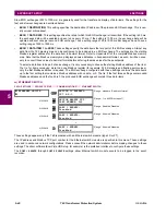
c) TRIP AND ALARM LEDS
PATH: SETTINGS
PRODUCT SETUP
USER-PROGRAMMABLE LEDS
TRIP & ALARM LEDS
The trip and alarm LEDs are in the first LED column (enhanced faceplate) and on LED panel 1 (standard faceplate). Each
indicator can be programmed to become illuminated when the selected FlexLogic™ operand is in the logic 1 state.
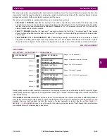
d) USER-PROGRAMMABLE LED 1(48)
PATH: SETTINGS
PRODUCT SETUP
USER-PROGRAMMABLE LEDS
USER-PROGRAMMABLE LED 1(48)
There are 48 amber LEDs across the relay faceplate LED panels. Each of these indicators can be programmed to illumi-
nate when the selected FlexLogic™ operand is in the logic 1 state.
For the standard faceplate, the LEDs are located as follows.
•
LED Panel 2: user-programmable LEDs 1 through 24
•
LED Panel 3: user programmable LEDs 25 through 48
For the enhanced faceplate, the LEDs are located as follows.
•
LED column 2: user-programmable LEDs 1 through 12
•
LED column 3: user-programmable LEDs 13 through 24
•
LED column 4: user-programmable LEDs 25 through 36
•
LED column 5: user-programmable LEDs 37 through 48
Refer to the
LED indicators
section in chapter 4 for additional information on the location of these indexed LEDs.
The user-programmable LED settings select the FlexLogic™ operands that control the LEDs. If the
LED 1 TYPE
setting is
“Self-Reset” (the default setting), the LED illumination will track the state of the selected LED operand. If the
LED 1 TYPE
set-
ting is “Latched”, the LED, once lit, remains so until reset by the faceplate RESET button, from a remote device via a com-
munications channel, or from any programmed operand, even if the LED operand state de-asserts.
TRIP & ALARM LEDS
TRIP LED INPUT:
Off
Range: FlexLogic™ operand
MESSAGE
ALARM LED INPUT:
Off
Range: FlexLogic™ operand
USER-PROGRAMMABLE
LED 1
LED 1 OPERAND:
Off
Range: FlexLogic™ operand
MESSAGE
LED 1 TYPE:
Self-Reset
Range: Self-Reset, Latched
Table 5–4: RECOMMENDED SETTINGS FOR USER-PROGRAMMABLE LEDS
SETTING
PARAMETER
SETTING
PARAMETER
LED 1 operand
SETTING GROUP ACT 1
LED 13 operand
Off
LED 2 operand
SETTING GROUP ACT 2
LED 14 operand
Off
LED 3 operand
SETTING GROUP ACT 3
LED 15 operand
Off
LED 4 operand
SETTING GROUP ACT 4
LED 16 operand
Off
LED 5 operand
SETTING GROUP ACT 5
LED 17 operand
Off
LED 6 operand
SETTING GROUP ACT 6
LED 18 operand
Off
LED 7 operand
Off
LED 19 operand
Off
LED 8 operand
Off
LED 20 operand
Off
LED 9 operand
Off
LED 21 operand
Off
LED 10 operand
Off
LED 22 operand
Off
LED 11 operand
Off
LED 23 operand
Off
LED 12 operand
Off
LED 24 operand
Off
Содержание UR T60
Страница 10: ...x T60 Transformer Protection System GE Multilin TABLE OF CONTENTS ...
Страница 14: ...xiv T60 Transformer Protection System GE Multilin 0 1 BATTERY DISPOSAL 0 BATTERY DISPOSAL 0 ...
Страница 34: ...1 20 T60 Transformer Protection System GE Multilin 1 5 USING THE RELAY 1 GETTING STARTED 1 ...
Страница 436: ...5 298 T60 Transformer Protection System GE Multilin 5 10 TESTING 5 SETTINGS 5 ...
Страница 492: ...8 18 T60 Transformer Protection System GE Multilin 8 3 ENERVISTA SECURITY MANAGEMENT SYSTEM 8 SECURITY 8 ...
Страница 510: ...9 18 T60 Transformer Protection System GE Multilin 9 6 COMMISSIONING TEST TABLES 9 COMMISSIONING 9 ...
Страница 678: ...C 30 T60 Transformer Protection System GE Multilin C 7 LOGICAL NODES APPENDIX C C ...
Страница 688: ...D 10 T60 Transformer Protection System GE Multilin D 1 IEC 60870 5 104 PROTOCOL APPENDIX D D ...
Страница 700: ...E 12 T60 Transformer Protection System GE Multilin E 2 DNP POINT LISTS APPENDIX E E ...


