


5-200
L90 Line Current Differential System
GE Multilin
5.6 GROUPED ELEMENTS
5 SETTINGS
5
b) NEUTRAL TIME OVERCURRENT
(ANSI 51N, IEC PTOC)
PATH: SETTINGS
GROUPED ELEMENTS
SETTING GROUP 1(6)
NEUTRAL CURRENT
NEUTRAL TOC1(2)
The neutral time overcurrent element can provide a desired time-delay operating characteristic versus the applied current
or be used as a simple definite time element. The neutral current input value is a quantity calculated as 3Io from the phase
currents and may be programmed as fundamental phasor magnitude or total waveform RMS magnitude as required by the
application.
Two methods of resetting operation are available: “Timed” and “Instantaneous” (refer to the
Inverse time overcurrent curve
characteristics
section for details on curve setup, trip times and reset operation). When the element is blocked, the time
accumulator will reset according to the reset characteristic. For example, if the element reset characteristic is set to “Instan-
taneous” and the element is blocked, the time accumulator will be cleared immediately.
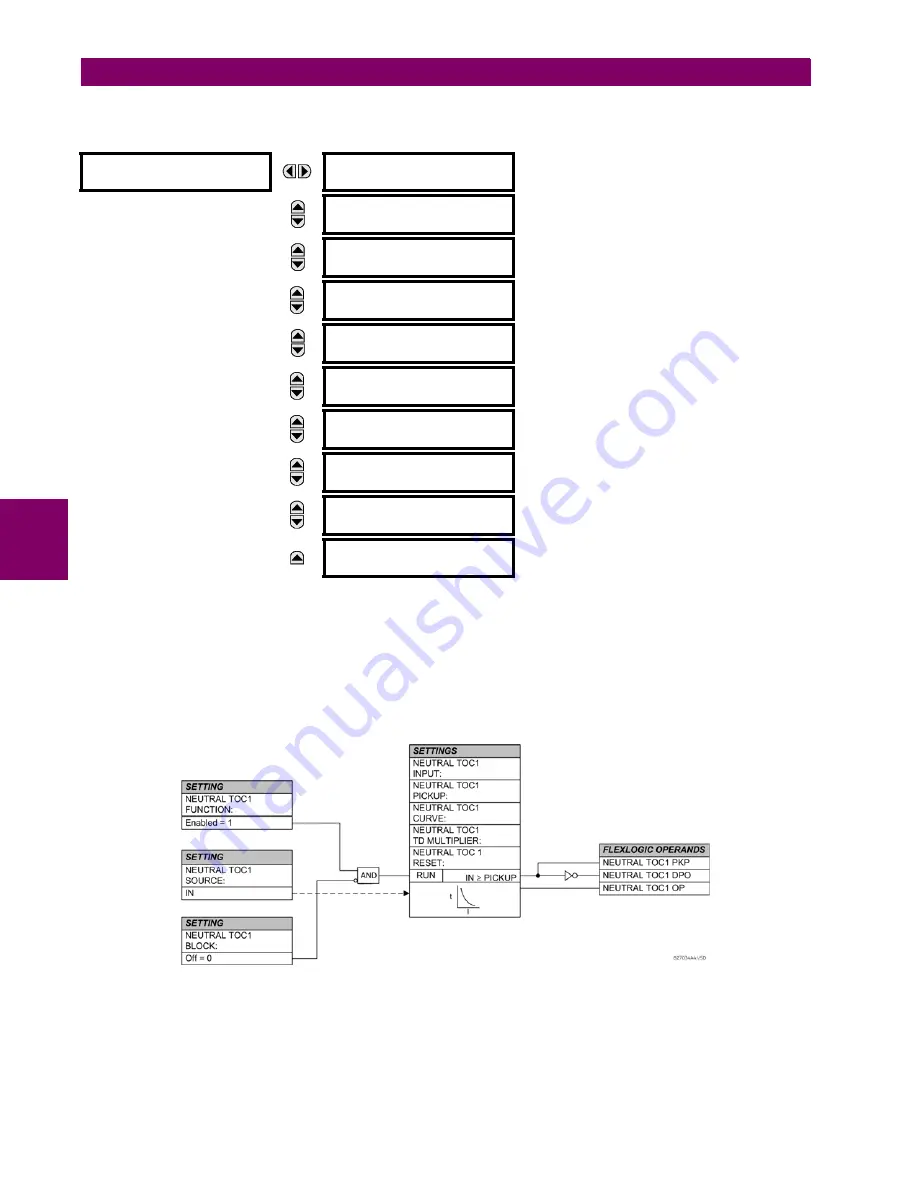
Figure 5–99: NEUTRAL TIME OVERCURRENT 1 SCHEME LOGIC
NEUTRAL TOC1
NEUTRAL TOC1
FUNCTION: Disabled
Range: Disabled, Enabled
MESSAGE
NEUTRAL TOC1 SIGNAL
SOURCE: SRC 1
Range: SRC 1, SRC 2, SRC 3, SRC 4
MESSAGE
NEUTRAL TOC1
INPUT: Phasor
Range: Phasor, RMS
MESSAGE
NEUTRAL TOC1
PICKUP: 1.000
pu
Range: 0.000 to 30.000 pu in steps of 0.001
MESSAGE
NEUTRAL TOC1
CURVE: IEEE Mod Inv
Range: See OVERCURRENT CURVE TYPES table
MESSAGE
NEUTRAL TOC1
TD MULTIPLIER: 1.00
Range: 0.00 to 600.00 in steps of 0.01
MESSAGE
NEUTRAL TOC1
RESET: Instantaneous
Range: Instantaneous, Timed
MESSAGE
NEUTRAL TOC1 BLOCK:
Off
Range: FlexLogic operand
MESSAGE
NEUTRAL TOC1
TARGET: Self-reset
Range: Self-reset, Latched, Disabled
MESSAGE
NEUTRAL TOC1
EVENTS: Disabled
Range: Disabled, Enabled
Содержание UR Series L90
Страница 14: ...xiv L90 Line Current Differential System GE Multilin 0 1 BATTERY DISPOSAL 0 BATTERY DISPOSAL 0 ...
Страница 68: ...2 34 L90 Line Current Differential System GE Multilin 2 4 SPECIFICATIONS 2 PRODUCT DESCRIPTION 2 ...
Страница 138: ...4 30 L90 Line Current Differential System GE Multilin 4 3 FACEPLATE INTERFACE 4 HUMAN INTERFACES 4 ...
Страница 604: ...9 58 L90 Line Current Differential System GE Multilin 9 6 FAULT LOCATOR 9 THEORY OF OPERATION 9 ...
Страница 652: ...A 16 L90 Line Current Differential System GE Multilin A 1 PARAMETER LISTS APPENDIX A A ...
Страница 772: ...B 120 L90 Line Current Differential System GE Multilin B 4 MEMORY MAPPING APPENDIX B B ...
Страница 802: ...C 30 L90 Line Current Differential System GE Multilin C 7 LOGICAL NODES APPENDIX C C ...
Страница 812: ...D 10 L90 Line Current Differential System GE Multilin D 1 IEC 60870 5 104 APPENDIX D D ...
Страница 824: ...E 12 L90 Line Current Differential System GE Multilin E 2 DNP POINT LISTS APPENDIX E E ...
Страница 834: ...F 10 L90 Line Current Differential System GE Multilin F 3 WARRANTY APPENDIX F F ...
Страница 846: ...xii L90 Line Current Differential System GE Multilin INDEX ...


