


GE Multilin
L90 Line Current Differential System
1-17
1 GETTING STARTED
1.4 UR HARDWARE
1
1.4UR HARDWARE
1.4.1 MOUNTING AND WIRING
See Chapter 3: Hardware for mounting and wiring instructions.
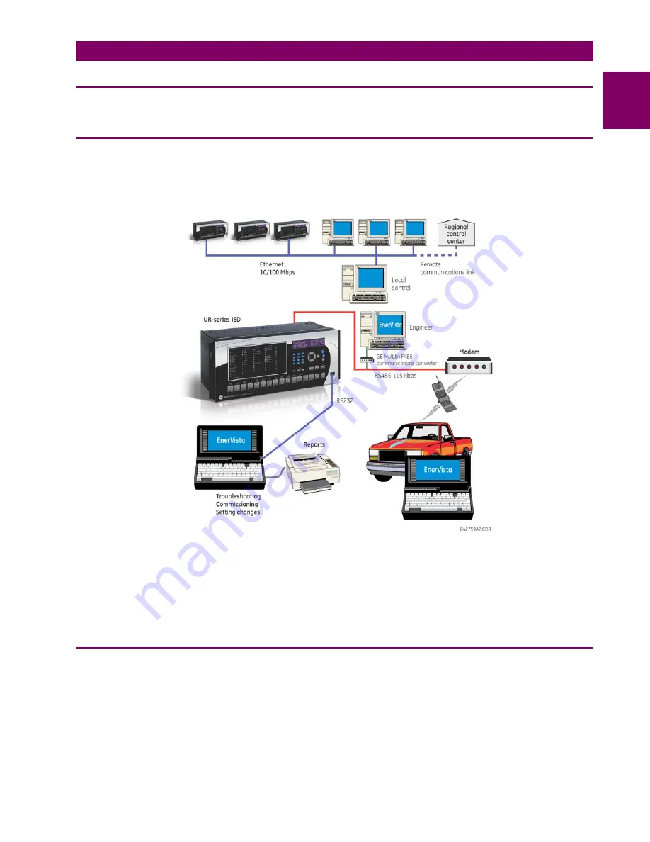
1.4.2 COMMUNICATIONS
The EnerVista UR Setup software communicates to the relay via the faceplate RS232 port or the rear panel RS485 / Ether-
net ports. To communicate via the faceplate RS232 port, a standard straight-through serial cable is used. The DB-9 male
end is connected to the relay and the DB-9 or DB-25 female end is connected to the computer COM2 port as described in
the
CPU communications ports
section of chapter 3.
Figure 1–7: RELAY COMMUNICATION OPTIONS
To communicate through the L90 rear RS485 port from a computer RS232 port, the GE Multilin RS232/RS485 converter
box is required. This device (catalog number F485) connects to the computer using a straight-through serial cable. A
shielded twisted-pair (20, 22, or 24 AWG) connects the F485 converter to the L90 rear communications port. The converter
terminals (+, –, GND) are connected to the L90 communication module (+, –, COM) terminals. See the
CPU communica-
tions ports
section in chapter 3 for details. The line is terminated with an R-C network (that is, 120
, 1 nF) as described in
the chapter 3.
1.4.3 FACEPLATE DISPLAY
All messages are displayed on a backlit liquid crystal display (LCD) to make them visible under poor lighting conditions.
While the keypad and display are not actively being used, the display defaults to user-defined messages. Any high-priority
event-driven message automatically overrides the default message and appears on the display.
Содержание UR Series L90
Страница 14: ...xiv L90 Line Current Differential System GE Multilin 0 1 BATTERY DISPOSAL 0 BATTERY DISPOSAL 0 ...
Страница 68: ...2 34 L90 Line Current Differential System GE Multilin 2 4 SPECIFICATIONS 2 PRODUCT DESCRIPTION 2 ...
Страница 138: ...4 30 L90 Line Current Differential System GE Multilin 4 3 FACEPLATE INTERFACE 4 HUMAN INTERFACES 4 ...
Страница 604: ...9 58 L90 Line Current Differential System GE Multilin 9 6 FAULT LOCATOR 9 THEORY OF OPERATION 9 ...
Страница 652: ...A 16 L90 Line Current Differential System GE Multilin A 1 PARAMETER LISTS APPENDIX A A ...
Страница 772: ...B 120 L90 Line Current Differential System GE Multilin B 4 MEMORY MAPPING APPENDIX B B ...
Страница 802: ...C 30 L90 Line Current Differential System GE Multilin C 7 LOGICAL NODES APPENDIX C C ...
Страница 812: ...D 10 L90 Line Current Differential System GE Multilin D 1 IEC 60870 5 104 APPENDIX D D ...
Страница 824: ...E 12 L90 Line Current Differential System GE Multilin E 2 DNP POINT LISTS APPENDIX E E ...
Страница 834: ...F 10 L90 Line Current Differential System GE Multilin F 3 WARRANTY APPENDIX F F ...
Страница 846: ...xii L90 Line Current Differential System GE Multilin INDEX ...


