


GE Multilin
L90 Line Current Differential System
1-9
1 GETTING STARTED
1.3 ENERVISTA UR SETUP SOFTWARE
1
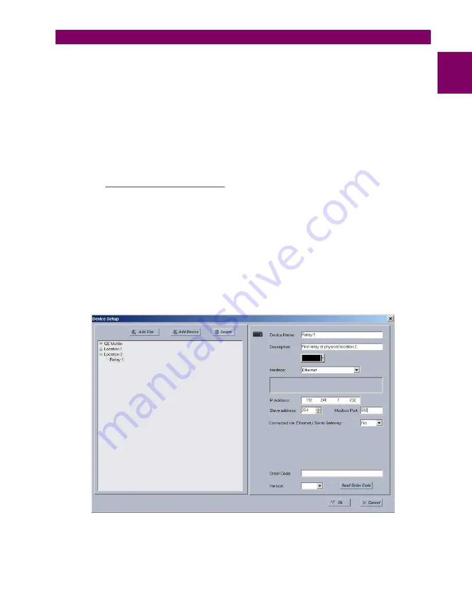
10. Click the
Read Order Code
button to connect to the L90 device and upload the order code. If a communications error
occurs, ensure that the EnerVista UR Setup serial communications values entered in the previous step correspond to
the relay setting values.
11. Click the
OK
button when the relay order code has been received. The new device is added to the Site List window (or
Online window) located in the top left corner of the main EnerVista UR Setup window.
The device has now been configured for RS232 communications. Proceed to the
Connecting to the L90
section to begin
communication.
c) CONFIGURING ETHERNET COMMUNICATIONS
Before starting, verify that the Ethernet network cable is properly connected to the Ethernet port on the back of the relay. To
setup the relay for Ethernet communications, you define a Site, then add the relay as a Device at that site.The computer
and UR device must be on the same subnet.
1.
Verify that the latest version of the EnerVista UR Setup software is installed (available from the GE EnerVista CD or
online from
http://www.gedigitalenergy.com/multilin
). See the
Software Installation
section for installation details.
2.
Select the “UR” device from the EnerVista Launchpad to start EnerVista UR Setup.
3.
Click the
Device Setup
button to open the Device Setup window, then click the
Add Site
button to define a new site.
4.
Enter the desired site name in the “Site Name” field. If desired, a short description of site can also be entered along
with the display order of devices defined for the site. In this example, we use “Location 2” as the site name. Click the
OK
button when complete.
5.
The new site appears in the upper-left list in the EnerVista UR Setup window. Click the
Device Setup
button then
select the new site to re-open the Device Setup window.
6.
Click the
Add Device
button to define the new device.
7.
Enter the desired name in the “Device Name” field and a description (optional) of the site.
8.
Select “Ethernet” from the
Interface
drop-down list. This displays a number of interface parameters that must be
entered for proper Ethernet functionality.
Figure 1–5: CONFIGURING ETHERNET COMMUNICATIONS
9.
Enter the relay IP address specified in the
SETTINGS
PRODUCT SETUP
COMMUNICATIONS
NETWORK
IP
ADDRESS
in the “IP Address” field.
Содержание UR Series L90
Страница 14: ...xiv L90 Line Current Differential System GE Multilin 0 1 BATTERY DISPOSAL 0 BATTERY DISPOSAL 0 ...
Страница 68: ...2 34 L90 Line Current Differential System GE Multilin 2 4 SPECIFICATIONS 2 PRODUCT DESCRIPTION 2 ...
Страница 138: ...4 30 L90 Line Current Differential System GE Multilin 4 3 FACEPLATE INTERFACE 4 HUMAN INTERFACES 4 ...
Страница 604: ...9 58 L90 Line Current Differential System GE Multilin 9 6 FAULT LOCATOR 9 THEORY OF OPERATION 9 ...
Страница 652: ...A 16 L90 Line Current Differential System GE Multilin A 1 PARAMETER LISTS APPENDIX A A ...
Страница 772: ...B 120 L90 Line Current Differential System GE Multilin B 4 MEMORY MAPPING APPENDIX B B ...
Страница 802: ...C 30 L90 Line Current Differential System GE Multilin C 7 LOGICAL NODES APPENDIX C C ...
Страница 812: ...D 10 L90 Line Current Differential System GE Multilin D 1 IEC 60870 5 104 APPENDIX D D ...
Страница 824: ...E 12 L90 Line Current Differential System GE Multilin E 2 DNP POINT LISTS APPENDIX E E ...
Страница 834: ...F 10 L90 Line Current Differential System GE Multilin F 3 WARRANTY APPENDIX F F ...
Страница 846: ...xii L90 Line Current Differential System GE Multilin INDEX ...


