6-4
C70 Capacitor Bank Protection and Control System
GE Multilin
6.2 STATUS
6 ACTUAL VALUES
6
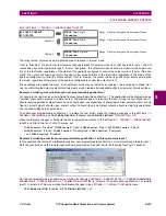
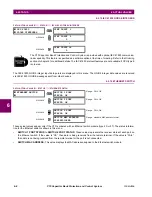
6.2.4 REMOTE DOUBLE-POINT STATUS INPUTS
PATH: ACTUAL VALUES
Ö
STATUS
ÖØ
REMOTE DPS INPUTS
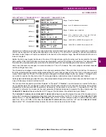
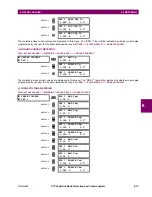
The present state of the remote double-point status inputs is shown here. The actual values indicate if the remote double-
point status inputs are in the on (close), off (open), intermediate, or bad state.
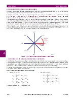
6.2.5 CONTACT OUTPUTS
PATH: ACTUAL VALUES
Ö
STATUS
ÖØ
CONTACT OUTPUTS
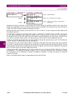
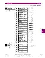
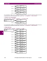
The present state of the contact outputs is shown here. The first line of a message display indicates the ID of the contact
output. For example, ‘Cont Op 1’ refers to the contact output in terms of the default name-array index. The second line of
the display indicates the logic state of the contact output.
For form-A contact outputs, the state of the voltage and current detectors is displayed as Off, VOff, IOff,
On, IOn, and VOn. For form-C contact outputs, the state is displayed as Off or On.
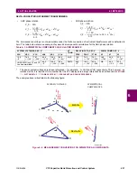
6.2.6 VIRTUAL OUTPUTS
PATH: ACTUAL VALUES
Ö
STATUS
ÖØ
VIRTUAL OUTPUTS
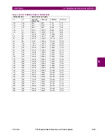
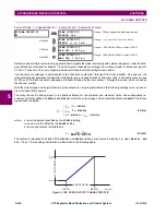
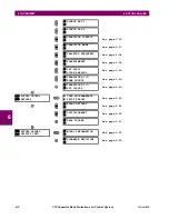
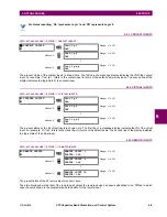
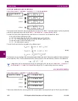
The present state of up to 96 virtual outputs is shown here. The first line of a message display indicates the ID of the virtual
output. For example, ‘Virt Op 1’ refers to the virtual output in terms of the default name-array index. The second line of the
display indicates the logic state of the virtual output, as calculated by the FlexLogic™ equation for that output.
REMOTE DPS INPUTS
REMOTE DPS INPUT 1
STATUS: Bad
Range: On, Off, Intermediate, Bad
MESSAGE
REMOTE DPS INPUT 2
STATUS: Bad
Range: On, Off, Intermediate, Bad
↓
MESSAGE
REMOTE DPS INPUT 5
STATUS: Bad
Range: On, Off, Intermediate, Bad
CONTACT OUTPUTS
Cont Op 1
Off
Range: On, Off, VOff, VOn, IOn, IOff
MESSAGE
Cont Op 2
Off
Range: On, Off, VOff, VOn, IOn, IOff
↓
MESSAGE
Cont Op xx
Off
Range: On, Off, VOff, VOn, IOn, IOff
VIRTUAL OUTPUTS
Virt Op 1
Off
Range: On, Off
MESSAGE
Virt Op 2
Off
Range: On, Off
↓
MESSAGE
Virt Op 96
Off
Range: On, Off
NOTE
Содержание UR Series C70
Страница 2: ......
Страница 10: ...x C70 Capacitor Bank Protection and Control System GE Multilin TABLE OF CONTENTS ...
Страница 30: ...1 20 C70 Capacitor Bank Protection and Control System GE Multilin 1 5 USING THE RELAY 1 GETTING STARTED 1 ...
Страница 124: ...4 30 C70 Capacitor Bank Protection and Control System GE Multilin 4 3 FACEPLATE INTERFACE 4 HUMAN INTERFACES 4 ...
Страница 344: ...5 220 C70 Capacitor Bank Protection and Control System GE Multilin 5 10 TESTING 5 SETTINGS 5 ...
Страница 396: ...8 18 C70 Capacitor Bank Protection and Control System GE Multilin 8 3 ENERVISTA SECURITY MANAGEMENT SYSTEM 8 SECURITY 8 ...
Страница 414: ...9 18 C70 Capacitor Bank Protection and Control System GE Multilin 9 1 OVERVIEW 9 THEORY OF OPERATION 9 ...
Страница 436: ...10 22 C70 Capacitor Bank Protection and Control System GE Multilin 10 4 SETTING EXAMPLE 10 APPLICATION OF SETTINGS 10 ...
Страница 547: ...GE Multilin C70 Capacitor Bank Protection and Control System B 79 APPENDIX B B 4 MEMORY MAPPING B ...
Страница 548: ...B 80 C70 Capacitor Bank Protection and Control System GE Multilin B 4 MEMORY MAPPING APPENDIXB B ...
Страница 586: ...D 10 C70 Capacitor Bank Protection and Control System GE Multilin D 1 OVERVIEW APPENDIXD D ...
Страница 598: ...E 12 C70 Capacitor Bank Protection and Control System GE Multilin E 2 DNP POINT LISTS APPENDIXE E ...


