GE Multilin
C70 Capacitor Bank Protection and Control System
5-177
5 SETTINGS
5.7 CONTROL ELEMENTS
5
5.7.7 AUTOMATIC VOLTAGE REGULATOR
PATH: SETTINGS
ÖØ
CONTROL ELEMENTS
ÖØ
AUTOMATIC VOLTAGE REGULATOR
Ö
AUTOMATIC VOLTAGE REGULATOR 1(3)
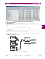
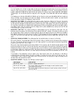
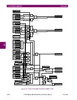
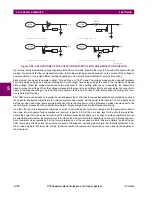
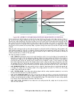
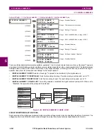
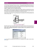
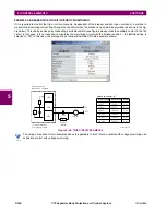
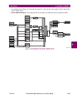
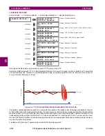
The automatic voltage regulator element (AVR) is intended to switch a static capacitor bank breaker close and open to reg-
ulate either system voltage, load voltage, power factor, or reactive power. The following figure illustrates some possible
applications.
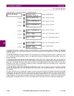
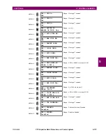
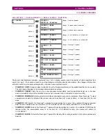
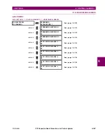
AUTOMATIC VOLTAGE
REGULATOR 1
AVR 1 FUNCTION:
Disabled
Range: Disabled, Enabled
MESSAGE
AVR 1 SOURCE:
SRC 1
Range: SRC 1, SRC 2, SRC 3, SRC 4, SRC 5, SRC 6
MESSAGE
AVR 1 MINIMUM
VOLTAGE: 0.500 pu
Range: 0.500 to 1.500 pu in steps of 0.001
MESSAGE
AVR 1 CONTROL MODE:
Voltage
Range: Voltage, VAR
MESSAGE
AVR 1 VOLT OPERATING
SIGNAL: V1
Range: Vab, Vbc, Vca, Vaver, V1, Vaux, Vag, Vbg, Vcg
MESSAGE
AVR 1 VOLT LEVEL TO
CLOSE: 0.950 pu
Range: 0.750 to 1.500 pu in steps of 0.001
MESSAGE
AVR 1 VOLT LEVEL TO
OPEN: 1.050 pu
Range: 0.750 to 1.500 pu in steps of 0.001
MESSAGE
AVR 1 VOLT DROP
COMPENS Z: 0.00
Ω
Range: 0 to 250.00 ohms in steps of 0.01
MESSAGE
AVR 1 VOLT DROP
COMPENS RCA: 75°
Range: 30 to 90° in steps of 1
MESSAGE
AVR 1 VAR LEVEL TO
CLOSE: 0.500 pu
Range: –1.500 to 1.500 pu in steps of 0.001
MESSAGE
AVR 1 VAR LEVEL TO
OPEN: -0.500 pu
Range: –1.500 to 1.500 pu in steps of 0.001
MESSAGE
AVR 1 POWER FACTOR
LIMIT: 1.00
Range: 0.50 to 1.00 pu in steps of 0.01
MESSAGE
AVR 1 VAR OPEN MODE:
Minimize No. of Ops.
Range: Minimize Uptime, Minimize No. of Ops.
MESSAGE
AVR 1 DELAY BEFORE
CLOSE: 1.000 s
Range: 0.000 to 65.353 s in steps of 0.001
MESSAGE
AVR 1 DELAY BEFORE
OPEN: 1.000 s
Range: 0.000 to 65.353 s in steps of 0.001
MESSAGE
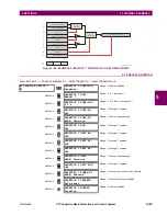
AVR 1 BLOCK:
Off
Range: FlexLogic™ operand
MESSAGE
AVR 1 TARGET:
Self-reset
Range: Self-reset, Latched, Disabled
MESSAGE
AVR 1 EVENTS:
Disabled
Range: Disabled, Enabled
Содержание UR Series C70
Страница 2: ......
Страница 10: ...x C70 Capacitor Bank Protection and Control System GE Multilin TABLE OF CONTENTS ...
Страница 30: ...1 20 C70 Capacitor Bank Protection and Control System GE Multilin 1 5 USING THE RELAY 1 GETTING STARTED 1 ...
Страница 124: ...4 30 C70 Capacitor Bank Protection and Control System GE Multilin 4 3 FACEPLATE INTERFACE 4 HUMAN INTERFACES 4 ...
Страница 344: ...5 220 C70 Capacitor Bank Protection and Control System GE Multilin 5 10 TESTING 5 SETTINGS 5 ...
Страница 396: ...8 18 C70 Capacitor Bank Protection and Control System GE Multilin 8 3 ENERVISTA SECURITY MANAGEMENT SYSTEM 8 SECURITY 8 ...
Страница 414: ...9 18 C70 Capacitor Bank Protection and Control System GE Multilin 9 1 OVERVIEW 9 THEORY OF OPERATION 9 ...
Страница 436: ...10 22 C70 Capacitor Bank Protection and Control System GE Multilin 10 4 SETTING EXAMPLE 10 APPLICATION OF SETTINGS 10 ...
Страница 547: ...GE Multilin C70 Capacitor Bank Protection and Control System B 79 APPENDIX B B 4 MEMORY MAPPING B ...
Страница 548: ...B 80 C70 Capacitor Bank Protection and Control System GE Multilin B 4 MEMORY MAPPING APPENDIXB B ...
Страница 586: ...D 10 C70 Capacitor Bank Protection and Control System GE Multilin D 1 OVERVIEW APPENDIXD D ...
Страница 598: ...E 12 C70 Capacitor Bank Protection and Control System GE Multilin E 2 DNP POINT LISTS APPENDIXE E ...

