


5-20
C70 Capacitor Bank Protection and Control System
GE Multilin
5.2 PRODUCT SETUP
5 SETTINGS
5
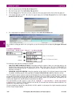
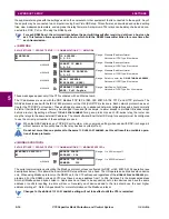
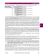
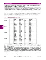
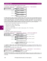
master can operate a single point for both trip and close, or raise and lower, operations. The C70 can be configured to sup-
port paired control points, with each paired control point operating two virtual inputs. The
DNP NUMBER OF PAIRED CONTROL
POINTS
setting allows configuration of from 0 to 32 binary output paired controls. Points not configured as paired operate on
a one-to-one basis.
The
DNP ADDRESS
setting is the DNP slave address. This number identifies the C70 on a DNP communications link. Each
DNP slave should be assigned a unique address.
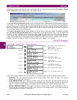
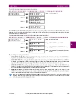
The
DNP TCP CONNECTION TIMEOUT
setting specifies a time delay for the detection of dead network TCP connections. If
there is no data traffic on a DNP TCP connection for greater than the time specified by this setting, the connection will be
aborted by the C70. This frees up the connection to be re-used by a client.
Relay power must be re-cycled after changing the
DNP TCP CONNECTION TIMEOUT
setting for the changes to take
effect.
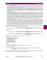
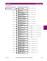
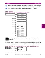
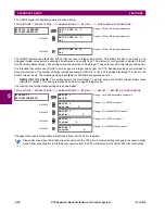
f) DNP / IEC 60870-5-104 POINT LISTS
PATH: SETTINGS
Ö
PRODUCT SETUP
ÖØ
COMMUNICATIONS
ÖØ
DNP / IEC104 POINT LISTS
The binary and analog inputs points for the DNP protocol, or the MSP and MME points for IEC 60870-5-104 protocol, can
configured to a maximum of 256 points. The value for each point is user-programmable and can be configured by assigning
FlexLogic™ operands for binary inputs / MSP points or FlexAnalog parameters for analog inputs / MME points.
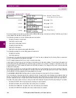
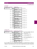
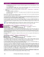
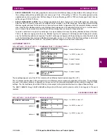
The menu for the binary input points (DNP) or MSP points (IEC 60870-5-104) is shown below.
PATH: SETTINGS
Ö
PRODUCT SETUP
ÖØ
COMMUNICATIONS
ÖØ
DNP / IEC104 POINT LISTS
Ö
BINARY INPUT / MSP POINTS
Up to 256 binary input points can be configured for the DNP or IEC 60870-5-104 protocols. The points are configured by
assigning an appropriate FlexLogic™ operand. Refer to the
Introduction to FlexLogic™
section in this chapter for the full
range of assignable operands.
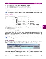
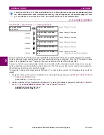
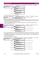
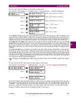
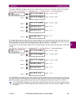
The menu for the analog input points (DNP) or MME points (IEC 60870-5-104) is shown below.
PATH: SETTINGS
Ö
PRODUCT SETUP
ÖØ
COMMUNICATIONS
ÖØ
DNP / IEC104 POINT LISTS
ÖØ
ANALOG INPUT / MME POINTS
Up to 256 analog input points can be configured for the DNP or IEC 60870-5-104 protocols. The analog point list is config-
ured by assigning an appropriate FlexAnalog parameter to each point. Refer to Appendix A:
FlexAnalog Parameters
for the
full range of assignable parameters.
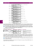
DNP / IEC104
POINT LISTS
BINARY INPUT / MSP
POINTS
Range: see sub-menu below
MESSAGE
ANALOG INPUT / MME
POINTS
Range: see sub-menu below
BINARY INPUT / MSP
POINTS
Point:
0
Off
Range: FlexLogic™ operand
MESSAGE
Point:
1
Off
Range: FlexLogic™ operand
↓
MESSAGE
Point:
255
Off
Range: FlexLogic™ operand
ANALOG INPUT / MME
POINTS
Point:
0
Off
Range: any FlexAnalog parameter
MESSAGE
Point:
1
Off
Range: any FlexAnalog parameter
↓
MESSAGE
Point:
255
Off
Range: any FlexAnalog parameter
NOTE
Содержание UR Series C70
Страница 2: ......
Страница 10: ...x C70 Capacitor Bank Protection and Control System GE Multilin TABLE OF CONTENTS ...
Страница 30: ...1 20 C70 Capacitor Bank Protection and Control System GE Multilin 1 5 USING THE RELAY 1 GETTING STARTED 1 ...
Страница 124: ...4 30 C70 Capacitor Bank Protection and Control System GE Multilin 4 3 FACEPLATE INTERFACE 4 HUMAN INTERFACES 4 ...
Страница 344: ...5 220 C70 Capacitor Bank Protection and Control System GE Multilin 5 10 TESTING 5 SETTINGS 5 ...
Страница 396: ...8 18 C70 Capacitor Bank Protection and Control System GE Multilin 8 3 ENERVISTA SECURITY MANAGEMENT SYSTEM 8 SECURITY 8 ...
Страница 414: ...9 18 C70 Capacitor Bank Protection and Control System GE Multilin 9 1 OVERVIEW 9 THEORY OF OPERATION 9 ...
Страница 436: ...10 22 C70 Capacitor Bank Protection and Control System GE Multilin 10 4 SETTING EXAMPLE 10 APPLICATION OF SETTINGS 10 ...
Страница 547: ...GE Multilin C70 Capacitor Bank Protection and Control System B 79 APPENDIX B B 4 MEMORY MAPPING B ...
Страница 548: ...B 80 C70 Capacitor Bank Protection and Control System GE Multilin B 4 MEMORY MAPPING APPENDIXB B ...
Страница 586: ...D 10 C70 Capacitor Bank Protection and Control System GE Multilin D 1 OVERVIEW APPENDIXD D ...
Страница 598: ...E 12 C70 Capacitor Bank Protection and Control System GE Multilin E 2 DNP POINT LISTS APPENDIXE E ...


