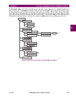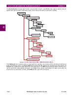
C-14
F35 Multiple Feeder Protection System
GE Multilin
C.5 IEC 61850 IMPLEMENTATION VIA ENERVISTA UR SETUP
APPENDIX C
C
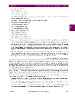
•
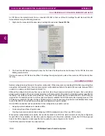
MMXU deadbands, which includes deadbands for all available MMXUs. The number of MMXUs is related to the num-
ber of CT/VT modules in the relay. There are two MMXUs for each CT/VT module. For example, if a relay contains two
CT/VT modules, there will be four MMXUs available (access through the
Settings > Product Setup > Communica-
tions > IEC 61850 > MMXU Deadbands
menu tree in EnerVista UR Setup).
•
GGIO1 status configuration, which includes the number of status points in GGIO1 as well as the potential internal map-
pings for each GGIO1 indication. However only the number of status points will be used in the ICD creation process
(access through the
Settings > Product Setup > Communications > IEC 61850 > GGIO1 Status Configuration
menu tree in EnerVista UR Setup).
•
GGIO2 control configuration, which includes ctlModels for all SPCSOs within GGIO2 (access through the
Settings >
Product Setup > Communications > IEC 61850 > GGIO2 Control Configuration
menu tree in EnerVista UR
Setup).
•
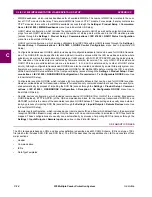
Configurable transmission GOOSE, which includes eight configurable datasets that can be used for GOOSE transmis-
sion. The GOOSE ID can be specified for each dataset (it must be unique within the IED as well as across the whole
substation), as well as the destination MAC address, VLAN priority, VLAN ID, ETYPE APPID, and the dataset items.
The selection of the dataset item is restricted by firmware version; for version 7.2x, only GGIO1.ST.Indx.stVal and
GGIO1.ST.Indx.q are valid selection (where
x
is between 1 to
N
, and
N
is determined by number of GGIO1 status
points). Although configurable transmission GOOSE can also be created and altered by some third-party system con-
figurators, we recommend configuring transmission GOOSE for GE Multilin IEDs before creating the ICD, and strictly
within EnerVista UR Setup software or the front panel display (access through the
Settings > Product Setup > Com-
munications > IEC 61850 > GSSE/GOOSE Configuration > Transmission > Tx Configurable GOOSE
menu tree
in EnerVista UR Setup).
•
Configurable reception GOOSE, which includes eight configurable datasets that can be used for GOOSE reception.
However, unlike datasets for transmission, datasets for reception only contains dataset items, and they are usually cre-
ated automatically by process of importing the SCD file (access through the
Settings > Product Setup > Communi-
cations > IEC 61850 > GSSE/GOOSE Configuration > Reception > Rx Configurable GOOSE
menu tree in
EnerVista UR Setup).
•
Remote devices configuration, which includes remote device ID (GOOSE ID or GoID of the incoming transmission
GOOSE dataset), ETYPE APPID (of the GSE communication block for the incoming transmission GOOSE), and
DATASET (which is the name of the associated reception GOOSE dataset). These settings are usually done automat-
ically by process of importing SCD file (access through the
Settings > Inputs/Outputs > Remote Devices
menu tree
in EnerVista UR Setup).
•
Remote inputs configuration, which includes device (remote device ID) and item (which dataset item in the associated
reception GOOSE dataset to map) values. Only the items with cross-communication link created in SCD file should be
mapped. These configurations are usually done automatically by process of importing SCD file (access through the
Settings > Inputs/Outputs > Remote Inputs
menu tree in EnerVista UR Setup).
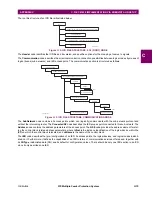
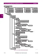
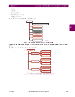
C.5.3 ABOUT ICD FILES
The SCL language is based on XML, and its syntax definition is described as a W3C XML Schema. ICD is one type of SCL
file (which also includes SSD, CID and SCD files). The ICD file describes the capabilities of an IED and consists of four
major sections:
•
Header
•
Communication
•
IEDs
•
DataTypeTemplates
Содержание UR F35 Series
Страница 10: ...x F35 Multiple Feeder Protection System GE Multilin TABLE OF CONTENTS ...
Страница 30: ...1 20 F35 Multiple Feeder Protection System GE Multilin 1 5 USING THE RELAY 1 GETTING STARTED 1 ...
Страница 366: ...5 238 F35 Multiple Feeder Protection System GE Multilin 5 10 TESTING 5 SETTINGS 5 ...
Страница 396: ...6 30 F35 Multiple Feeder Protection System GE Multilin 6 5 PRODUCT INFORMATION 6 ACTUAL VALUES 6 ...
Страница 412: ...8 4 F35 Multiple Feeder Protection System GE Multilin 8 1 FAULT LOCATOR 8 THEORY OF OPERATION 8 ...
Страница 426: ...10 12 F35 Multiple Feeder Protection System GE Multilin 10 6 DISPOSAL 10 MAINTENANCE 10 ...
Страница 454: ...A 28 F35 Multiple Feeder Protection System GE Multilin A 1 PARAMETER LISTS APPENDIX A A ...
Страница 608: ...E 10 F35 Multiple Feeder Protection System GE Multilin E 1 IEC 60870 5 104 PROTOCOL APPENDIX E E ...
Страница 620: ...F 12 F35 Multiple Feeder Protection System GE Multilin F 2 DNP POINT LISTS APPENDIX F F ...
Страница 630: ...H 8 F35 Multiple Feeder Protection System GE Multilin H 3 WARRANTY APPENDIX H H ...
Страница 640: ...x F35 Multiple Feeder Protection System GE Multilin INDEX ...

