2-10
T35 Transformer Protection System
GE Multilin
2.2 SPECIFICATIONS
2 PRODUCT DESCRIPTION
2
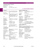
TRIP BUS (TRIP WITHOUT FLEXLOGIC)
Number of elements:
6
Number of inputs:
16
Operate time:
<2 ms at 60 Hz
Timer accuracy:
±3% or 10 ms, whichever is greater
2.2.2 USER-PROGRAMMABLE ELEMENTS
FLEXLOGIC
Programming language: Reverse Polish Notation with graphical
visualization (keypad programmable)
Lines of code:
512
Internal variables:
64
Supported operations:
NOT, XOR, OR (2 to 16 inputs), AND (2
to 16 inputs), NOR (2 to 16 inputs),
NAND (2 to 16 inputs), latch (reset-domi-
nant), edge detectors, timers
Inputs:
any logical variable, contact, or virtual
input
Number of timers:
32
Pickup delay:
0 to 60000 (ms, sec., min.) in steps of 1
Dropout delay:
0 to 60000 (ms, sec., min.) in steps of 1
FLEXCURVES™
Number:
4 (A through D)
Reset points:
40 (0 through 1 of pickup)
Operate points:
80 (1 through 20 of pickup)
Time delay:
0 to 65535 ms in steps of 1
FLEX STATES
Number:
up to 256 logical variables grouped
under 16 Modbus addresses
Programmability:
any logical variable, contact, or virtual
input
FLEXELEMENTS™
Number of elements:
16
Operating signal:
any analog actual value, or two values in
differential mode
Operating signal mode: signed or absolute value
Operating mode:
level, delta
Comparator direction:
over, under
Pickup Level:
–90.000 to 90.000 pu in steps of 0.001
Hysteresis:
0.1 to 50.0% in steps of 0.1
Delta dt:
20 ms to 60 days
Pickup & dropout delay: 0.000 to 65.535 s in steps of 0.001
NON-VOLATILE LATCHES
Type:
set-dominant or reset-dominant
Number:
16 (individually programmed)
Output:
stored in non-volatile memory
Execution sequence:
as input prior to protection, control, and
FlexLogic
USER-PROGRAMMABLE LEDs
Number:
48 plus trip and alarm
Programmability:
from any logical variable, contact, or vir-
tual input
Reset mode:
self-reset or latched
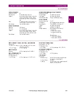
LED TEST
Initiation:
from any contact input or user-program-
mable condition
Number of tests:
3, interruptible at any time
Duration of full test:
approximately 3 minutes
Test sequence 1:
all LEDs on
Test sequence 2:
all LEDs off, one LED at a time on for 1 s
Test sequence 3:
all LEDs on, one LED at a time off for 1 s
USER-DEFINABLE DISPLAYS
Number of displays:
16
Lines of display:
2
×
20 alphanumeric characters
Parameters:
up to 5, any Modbus register addresses
Invoking and scrolling:
keypad, or any user-programmable con-
dition, including pushbuttons
CONTROL PUSHBUTTONS
Number of pushbuttons: 7
Operation:
drive FlexLogic operands
USER-PROGRAMMABLE PUSHBUTTONS (OPTIONAL)
Number of pushbuttons: 12 (standard faceplate);
16 (enhanced faceplate)
Mode:
self-reset, latched
Display message:
2 lines of 20 characters each
Drop-out timer:
0.00 to 60.00 s in steps of 0.05
Autoreset timer:
0.2 to 600.0 s in steps of 0.1
Hold timer:
0.0 to 10.0 s in steps of 0.1
SELECTOR SWITCH
Number of elements:
2
Upper position limit:
1 to 7 in steps of 1
Selecting mode:
time-out or acknowledge
Time-out timer:
3.0 to 60.0 s in steps of 0.1
Control inputs:
step-up and 3-bit
Power-up mode:
restore from non-volatile memory or syn-
chronize to a 3-bit control input or synch/
restore mode
Содержание T35 UR Series
Страница 10: ...x T35 Transformer Protection System GE Multilin TABLE OF CONTENTS ...
Страница 48: ...2 18 T35 Transformer Protection System GE Multilin 2 2 SPECIFICATIONS 2 PRODUCT DESCRIPTION 2 ...
Страница 314: ...5 192 T35 Transformer Protection System GE Multilin 5 10 TESTING 5 SETTINGS 5 ...
Страница 338: ...6 24 T35 Transformer Protection System GE Multilin 6 5 PRODUCT INFORMATION 6 ACTUAL VALUES 6 ...
Страница 350: ...7 12 T35 Transformer Protection System GE Multilin 7 2 TARGETS 7 COMMANDS AND TARGETS 7 ...
Страница 366: ...8 16 T35 Transformer Protection System GE Multilin 8 2 CYBERSENTRY 8 SECURITY 8 ...
Страница 382: ...9 16 T35 Transformer Protection System GE Multilin 9 5 COMMISSIONING TEST TABLES 9 COMMISSIONING 9 ...
Страница 406: ...A 14 T35 Transformer Protection System GE Multilin A 1 PARAMETER LISTS APPENDIX A A ...
Страница 540: ...D 10 T35 Transformer Protection System GE Multilin D 1 IEC 60870 5 104 PROTOCOL APPENDIX D D ...
Страница 552: ...E 12 T35 Transformer Protection System GE Multilin E 2 DNP POINT LISTS APPENDIX E E ...
Страница 560: ...F 8 T35 Transformer Protection System GE Multilin F 3 WARRANTY APPENDIX F F ...


