


GE Multilin
T35 Transformer Protection System
2-1
2 PRODUCT DESCRIPTION
2.1 INTRODUCTION
2
2 PRODUCT DESCRIPTION 2.1INTRODUCTION
2.1.1 OVERVIEW
The T35 Transformer Protection System is a microprocessor-based relay intended for protecting small, medium, and large
three-phase power transformers involved in complicated power system configurations. The relay is available with two to six
banks of three-phase inputs: either CTs or CTs and VTs.
Typical T35 applications include:
•
Transformers with windings connected between two or more breakers.
•
Transformers with windings without associated breakers, where the only available ones are those on buses, lines, or
feeders.
The percent and instantaneous differential elements are the primary protection elements. The backup protection elements,
such as instantaneous overcurrent, can be expressed in fully configurable FlexElements™. The relay can also be config-
ured to protect transformers with any phase shift between the windings and handle up to 32 times the ratio mismatch (see
the phase and magnitude compensation descriptions in chapter 5).
Voltage, current, and power metering is built into the relay as a standard feature. Current parameters are available as total
waveform RMS magnitude, or as fundamental frequency only RMS magnitude and angle (phasor).
Diagnostic features include an event recorder capable of storing 1024 time-tagged events, oscillography capable of storing
up to 64 records with programmable trigger, content and sampling rate, and data logger acquisition of up to 16 channels,
with programmable content and sampling rate. The internal clock used for time-tagging can be synchronized with an IRIG-
B signal, using the Simple Network Time Protocol (SNTP) over the Ethernet port, or using the Precision Time Protocol
(PTP). This precise time stamping allows the sequence of events to be determined throughout the system. Events can also
be programmed (via FlexLogic equations) to trigger oscillography data capture which may be set to record the measured
parameters before and after the event for viewing on a personal computer (PC). These tools significantly reduce trouble-
shooting time and simplify report generation in the event of a system fault.
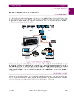
Several options are available for communication. A faceplate RS232 port can be used to connect to a computer for the pro-
gramming of settings and the monitoring of actual values. The RS232 port has a fixed baud rate of 19.2 kbps. The rear
RS485 port allows independent access by operating and engineering staff. It can be connected to system computers with
baud rates up to 115.2 kbps. All serial ports use the Modbus RTU protocol. The 100Base-FX or 100Base-T Ethernet inter-
face provides fast, reliable communications in noisy environments. The Ethernet port supports IEC 61850, Modbus/TCP,
and TFTP protocols, PTP (according to IEEE Std. 1588-2008 or IEC 61588), and allows access to the relay via any stan-
dard web browser (T35 web pages). The IEC 60870-5-104 protocol is supported on the Ethernet port. DNP 3.0 and IEC
60870-5-104 cannot be enabled at the same time. The Ethernet port also supports the Parallel Redundancy Protocol (PRP)
of IEC 62439-3 (clause 4, 2012) when purchased as an option.
Settings and actual values can be accessed from the front panel or EnerVista software.
The T35 IEDs use flash memory technology that allows field upgrading as new features are added.
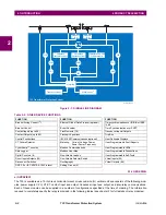
The following
Single line diagram
illustrates the relay functionality using ANSI (American National Standards Institute)
device numbers.
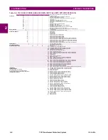
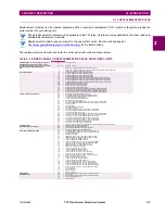
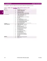
Table 2–1: ANSI DEVICE NUMBERS AND FUNCTIONS
DEVICE
NUMBER
FUNCTION
49
Thermal Overload Protection
50/87
Instantaneous Differential Overcurrent
51G
Ground Time Overcurrent
51P
Phase Time Overcurrent
87T
Transformer Differential
Содержание T35 UR Series
Страница 10: ...x T35 Transformer Protection System GE Multilin TABLE OF CONTENTS ...
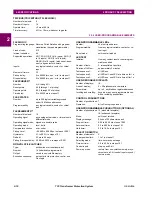
Страница 48: ...2 18 T35 Transformer Protection System GE Multilin 2 2 SPECIFICATIONS 2 PRODUCT DESCRIPTION 2 ...
Страница 314: ...5 192 T35 Transformer Protection System GE Multilin 5 10 TESTING 5 SETTINGS 5 ...
Страница 338: ...6 24 T35 Transformer Protection System GE Multilin 6 5 PRODUCT INFORMATION 6 ACTUAL VALUES 6 ...
Страница 350: ...7 12 T35 Transformer Protection System GE Multilin 7 2 TARGETS 7 COMMANDS AND TARGETS 7 ...
Страница 366: ...8 16 T35 Transformer Protection System GE Multilin 8 2 CYBERSENTRY 8 SECURITY 8 ...
Страница 382: ...9 16 T35 Transformer Protection System GE Multilin 9 5 COMMISSIONING TEST TABLES 9 COMMISSIONING 9 ...
Страница 406: ...A 14 T35 Transformer Protection System GE Multilin A 1 PARAMETER LISTS APPENDIX A A ...
Страница 540: ...D 10 T35 Transformer Protection System GE Multilin D 1 IEC 60870 5 104 PROTOCOL APPENDIX D D ...
Страница 552: ...E 12 T35 Transformer Protection System GE Multilin E 2 DNP POINT LISTS APPENDIX E E ...
Страница 560: ...F 8 T35 Transformer Protection System GE Multilin F 3 WARRANTY APPENDIX F F ...