


GE Healthcare
Senographe DS
Revision 1
Service Information and Procedures Class A 2385072-16-8EN
Job Card DIAG A010 - No Lift or Rotation Movement
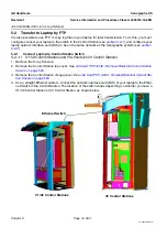
Page no. 1005
Chapter 9
JC-DIAG-A-010.fm
Job Card DIAG A010 - No Lift or Rotation Movement
Chapter 9
1
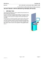
INTRODUCTION
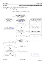
This Job Card is intended as an aid to troubleshooting when no lift or rotation movement is possible.
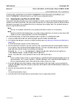
1-1. Schematic Concept of the Components Surrounding the H-Bridge
The following diagram shows a schematic concept of the components which control the H-Bridge on the
Lift DC Board PL201 and the Rotation DC Board PL202. This diagram is intended to provide operational
concepts rather than an actual circuit diagram.
The layout of the Lift DC Board and the Rotation DC Board can be found in
The H-Bridge is a group of components which includes a motor in the center and a MOS switch on each
branch. The bold lines in the diagram below define the branches of the H-Bridge. The direction of the
motor is determined by the pair of MOS switches that are closed (i.e. c for clockwise and a for anticlock-
wise). Movement is achieved by applying 48 V DC to the motor.
When there is a lift or rotation movement request by an Operator of the Senographe system, the Micro-
processor does the following:
•
gets the MOS Drive to close the appropriate pair of MOS switches on the H-Bridge (known as a
movement request)
•
closes the MOS 48 V DC Switch to supply the H-Bridge with 48 V
The microprocessor controls the states of the DS4 and DS8 diodes on the Lift DC Board and the Rota-
tion DC Board. The states of the DS4 and DS8 diodes vary according to the different situations that can
exist, and are summarized in the following table.
Situation
Diode state
H-Bridge health
Movement
DS4
DS8
If 48 V DC supply is ok
OK
Yes
ON
OFF
OK
No
OFF
ON
Faulty
No
Initially ON
then OFF
ON
MOS
Drive
Micr
oprocessor
DS4
Motor
+48 V
+0 V
MOS 48 V DC Switch
c
c
a
a
DS8
Movement request
H-Bridge


