background image

Chapter 3. Configuration 

62 

PACSystems* RX3i & RSTi-EP PROFINET IO-Controller User Manual 

GFK-2571N 

3.6


Configuring PROFINET LANs 

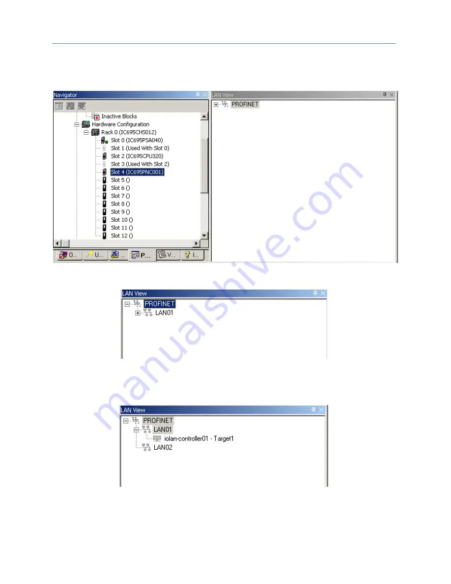
To view the LANs in the project, click on 

Tools

 in the Machine Edition toolbar, and select 

LAN View

 from the 

menu. If no LANs and no PROFINET Controllers have been added to the project, the LAN View is empty:  


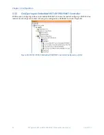
Figure 47: Configuring the PROFINET LAN 

Adding a PROFINET Controller to the project automatically creates a new LAN.  


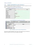
Figure 48: LAN Associated with PROFINET Controller 

Expand the LAN icon in the 

LAN View

 to see the modules it includes. 

A LAN can also be added to the project by right-clicking on the PROFINET icon in the 

LAN View

 and selecting 

Add LAN

.  


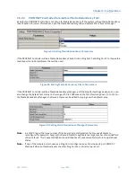
Figure 49: Adding a New LAN to the Configuration 

Содержание PACSystems* RX3i

Страница 1: ...ublic Disclosure GE Automation Controls Programmable Control Products RX3i RSTi EP PROFINET IO Controller User Manual GFK 2571N PACSystems RX3i RSTi EP PROFINET IO Controller User Manual GFK 2571N May...

Страница 2: ...E makes no warranty as to the accuracy of the information included herein Changes modifications and or improvements to equipment and specifications are made periodically and these changes may or may n...

Страница 3: ...lease contact us by telephone or email or on the web at www geautomation com support Americas Phone 1 800 433 2682 1 780 420 2010 if toll free 800 option is unavailable Email digitalsupport ge com Pri...

Страница 4: ...Module 13 1 6 PROFINET Networks for PACSystems 14 1 6 1 Compression 15 1 6 2 Basic System One RX3i CPU and One PROFINET Controller using a single port 16 1 6 3 Basic System One RX3i CPU and One PROFI...

Страница 5: ...8 PNC001 LED Behavior 43 2 8 1 Power up LED Patterns 43 2 8 2 Detailed LED Descriptions 44 2 9 Installing the USB Port Driver 46 2 10 Firmware Updates 47 2 10 1 PNC001 Firmware Updates 47 2 10 2 Firm...

Страница 6: ...es of a Third Party IO Device 78 3 9 Viewing Editing IO Device Properties 79 3 10 Assigning IO Device Names 81 3 11 After the Configuration is Stored to the RX3i CPU 83 Chapter 4 PROFINET System Opera...
Страница 7: ...ontroller 110 5 8 1 Faults Unique to Local Log Table 111 5 8 2 Viewing and Clearing the Local Log Table 113 5 9 PROFINET Controller Faults in the PACSystems Fault Tables 116 5 9 1 Clearing the PACSyst...

Страница 8: ...Features 143 7 1 3 SNMP Read Access 143 7 1 4 SNMP Write Access 143 7 1 5 MIB II Groups Supported 144 7 1 6 MIB II System Group Values 145 7 2 LLDP 146 7 2 1 Overview of LLDP 146 7 2 2 LLDP Operation...

Страница 9: ...38 Figure 24 Interconnect using Single Mode Fiber____________________________________________________ 38 Figure 25 CAT5e CAT6 shielded or unshielded with RJ 45 Connector _____________________________...

Страница 10: ...ess Point Tab _________________________________________ 76 Figure 75 Third Party I O Use of Media Redundancy Tab ____________________________________________ 76 Figure 76 Third Party I O Select Ring P...

Страница 11: ......

Страница 12: ...ctions for the corresponding PLC CPU Chapter 3 Configuration explains how to complete and download the PACSystems RX3i RSTi EP configuration for target PROFINET Controller as well as devices present o...

Страница 13: ...ounted PROFINET controllers F Dec 2016 Added information about embedded PROFINET Controllers in CPE400 and CPE330 Noted max loading and performance differences between embedded and rack mounted PROFIN...

Страница 14: ...products other than VersaMax support redundancy Chapter 4 PROFINET System Operation made edits to support redundancy Chapter 6 Redundant Media added table to show which PROFINET Scanner Device support...

Страница 15: ...wever 10Mbps can be used for other types of Ethernet traffic such as ping and telnet Features of the RX3i PNC001 module include Full programming and configuration services for the PROFINET Controller...

Страница 16: ...ontroller similar to PNC001 in functionality but without requiring the presence of a PNC001 rack mounted module In the following Specifications section the physical specifications related to rack moun...

Страница 17: ...s Number of PROFINET Port Connectors1 PNC001 2 RJ45 and 2 SFP Cages located on the underside of module SFP devices not included available separately Embedded PROFINET IO Controller 2 RJ45 Front Panel...

Страница 18: ...s per RX3i CPU Maximum of 255 simplex or 255 redundant I O Devices per RX3i CPU spread across up to four PROFINET Controllers 3 IO Devices per RSTi EP CPU Maximum of 8 simplex I O Devices for CPE100 C...

Страница 19: ...Controller as the MRP Ring Manager the maximum number of nodes is o for CPE330 CPE400 32 1 MRP Manager and 31 MRP clients o for CPE100 CPE115 9 1 MRP Manager and 8 MRP clients For a network using sta...

Страница 20: ...ature 1 4 1 Operating Temperature De Rating The operating temperature range is specified for the module and not the system as a whole As a guideline if the module is next to hot neighbor modules on ea...

Страница 21: ...roduction 10 PACSystems RX3i RSTi EP PROFINET IO Controller User Manual GFK 2571N 1 5 PNC001 Module Controls and Indicators Figure 2 IC695PNC001 Ax Controls Indicators Figure 3 IC695PNC001 Bxxx Contro...

Страница 22: ...t from rack No knockout removal required Status LEDs 6 LEDs 5 LEDs no USB LED LED Behavior See Section 2 8 See Section 2 8 Ethernet Port LEDs 4 singleton LEDs top of faceplate 4 banks of LEDs bottom o...

Страница 23: ...Ethernet ports and one for the internal switch Figure 4 PNC001 Ethernet Ports Location and Type For the Embedded PROFINET LAN LAN2 CPE400 and CPE330 both provide two RJ45 ports identical to those show...

Страница 24: ...cause A driver install application is provided to set up a computer to communicate with the USB port see Chapter 2 Installation for instructions 1 5 4 Reset Pushbutton The Reset pushbutton on a PNC00...

Страница 25: ...data and Alarms with PROFINET Controller Scans modules installed in its I O Rack IC695CEP001 RX3i CEP I O Drop PROFINET Scanner Head End for RX3i CEP I O Drop Exchanges I O data and Alarms with PROFI...

Страница 26: ...Compression when attaching RX3i PNS or CEP to their PROFINET configuration CPE302 User MUST use Target PLC parameter with Compression set to HIGH CPE305 User MUST use Target PLC parameter with Compre...

Страница 27: ...er and one PROFINET network with three VersaMax Scanners and one third party IO Device Up to 128 IO Devices can be installed on an RX3i PROFINET network The VersaMax PNS and many types of third party...

Страница 28: ...third party IO Devices Figure 7 shows one RX3i PROFINET Controller that is directly connected to four separate IO Devices in a Star topology Although each IO Device is connected to a separate Etherne...

Страница 29: ...T Controller connects to the third party IO Device if the device is available transfers the configuration to the device and starts exchanging I O and alarm data with the device Figure 8 shows a progra...

Страница 30: ...C001 are routed through the switch on a different PNC001 in the same rack devices may show a Loss of Device fault followed by an Addition of Device fault during RX3i power up because the first PNC001...

Страница 31: ...eparate networks The maximum number of IO Devices with multiple PROFINET Controllers in the same RX3i controller is 255 IO LAN 1 RX3i CPU Node w two PNCs IO Device IO Device IO Device IO Device IO LAN...

Страница 32: ...main rack and devices owned by one PNC001 are routed through the switch on a different PNC001 in the same rack devices may show a Loss of Device fault followed by an Addition of Device fault during RX...

Страница 33: ...LAN3 in the illustration Proficy Machine Edition PME HMI and Historian use LAN3 to configure and monitor the application LAN3 is also used for inter node communication such as EGD SRTP and Modbus TCP...

Страница 34: ...f something fails in one CPU controller the other CPU controller can continue IO operations without disruption PNSR relies entirely on PROFINET features to support this configuration PACSystems only s...

Страница 35: ...ms Hot Standby CPU Redundancy User s Manual GFK 2308F or later 1 6 9 1 Hot Standby CPU Redundancy Network with MRP Ring Topology I O I O I O I O P 2 P 1 P N S P S C P U R M X R M X P N C E T M P S C P...

Страница 36: ...ode with embedded PROFINET Controller and one PROFINET network with two VersaMax one RSTi EP Scanners and one third party IO Device Up to 8 IO Devices can be installed on an RSTi EP PROFINET network I...

Страница 37: ...vices including any combination of GE PROFINET Scanners and third party IO Devices Figure 16 shows one RSTi EP CPE100 CPE115 embedded PROFINET Controller that is directly connected to three separate I...

Страница 38: ...Port 3 support Media Redundancy and on configuring MRP as Manager Client LAN2 Port 4 can be used for connecting Simplex PROFINET devices or any other Ethernet Protocols such as Modbus SRTP and EGD Us...

Страница 39: ...ion Markup Language definition of PROFINET Device Characteristics IOC PROFINET IO Controller IOD PROFINET IO Device IOCR Input Output Communication Relationship describes the type input output and amo...

Страница 40: ...k of I O modules with a Remote Scanner or a third party PROFINET IO Device RIV Reference ID Variables RTA Real Time Acyclic A PROFINET IO Mechanism used to exchange non periodic data such as alarms RT...

Страница 41: ...troller Secure Deployment Guide GFK 2830 RX3i Manuals PACSystems RX3i System Manual GFK 2314 PACSystems RX3i PROFINET Controller Command Line Interface Manual GFK 2572 PACSystems RX3i Max On Hot Stand...

Страница 42: ...tion check Removing the backplane knockout Module installation and removal Hot insertion and removal Port connections Installing SFP devices LED indications Installing the USB Port Driver Firmware upd...

Страница 43: ...ols at GE Energy Connections will fully cooperate with you should such action be necessary After unpacking the RX3i equipment record all serial numbers Serial numbers are required if you should need t...

Страница 44: ...UTION OF COMPONENTS MAY IMPAIR SUITABILITY FOR CLASS I DIVISION 2 Warning EXPLOSION HAZARD WHEN IN HAZARDOUS LOCATIONS TURN OFF POWER BEFORE REPLACING OR WIRING MODULES Warning EXPLOSION HAZARD DO NOT...

Страница 45: ...r of the PNC001 Ax module has an exposed heat sink and backplane connector Before inserting the module into the backplane remove the plastic knockout in the slot into which the module will be placed T...

Страница 46: ...plate to 6 in lbs 0 68 Nm using a flat tip screwdriver PNC001 Bxxx Secure the bottom of the module to the backplane using the two captive Phillip s head machine screws provided with the module not sh...

Страница 47: ...area is non hazardous or remove system power appropriately before removing or inserting a module Warning If the surrounding air operating temperature of the PNC001 module is greater than 40 C 104 F SF...

Страница 48: ...e PROFINET Controller to the same device either directly or indirectly unless Media Redundancy is enabled in the PROFINET Controller s configuration If Media Redundancy will be used do not close the n...

Страница 49: ...nnections Copper cabling and connections are easily available in the general market and support distances of up to 100m Figure 22 Interconnect using Copper Cables RJ45 Connectors Multi Mode Fiber up t...

Страница 50: ...FK 2571N May 2018 39 2 7 2 2 Network Cabling and Connector Examples Figure 25 CAT5e CAT6 shielded or unshielded with RJ 45 Connector Figure 26 Multi Mode Fiber with LC connector Figure 27 Single Mode...

Страница 51: ...e open port if a cable is not installed Remove the protective plug to install the cable When the PNC001 powers up it automatically detects devices plugged into the SFP cages their type fiber copper et...

Страница 52: ...er than those listed below can be configured as a GENERIC SFP in Proficy Machine Edition The RX3i PROFINET Controller will attempt to operate with a generic SFP that identifies itself as an Ethernet S...

Страница 53: ...rounding air operating temperature of the PNC001 module is greater than 40 C 104 F SFP devices could reach operating temperatures over 70 C 158 F Under these conditions for your safety do not use bare...

Страница 54: ...id firmware detected Module is waiting for firmware update Blink pattern continues during firmware update 3 LAN and STATUS LED solid green PNC001 Ax only Normal operation 4 LAN LED solid green Normal...

Страница 55: ...vent is present in the module s Local Log STATUS can also indicate whether any of the MAC addresses are invalid The STATUS LED state is reset when the Local Log is cleared For more information see the...

Страница 56: ...corresponding LED Red ON Port 3 and 4 only Error such as incompatible SFP OFF No Port error 1000 Speed LED individual LED for each port Green ON Link connected 1000 Mbps Green blinking Port active 10...

Страница 57: ...gns a serial port name for the USB port on the PNC001 module A unique serial port number will be used for each PNC001 module The serial port name is COM followed by the next available number from 1 to...

Страница 58: ...uipped with a serial port use the http web based firmware update method For detailed instructions see the firmware upgrade instructions included in the ZIP file along with the firmware image file The...

Страница 59: ...ith the RX3i CPU clock whenever the PNC001 module is powered up or hot inserted or reset via the Reset pushbutton or on command from the Command Line Interface Storing hardware configuration to the PN...

Страница 60: ...nfiguring PROFINET Controller Parameters Configuring PROFINET LANs o Configuring the LAN Properties Adding a VersaMax PROFINET Scanner to a LAN o Configuring VersaMax PNS Parameters o Adding VersaMax...

Страница 61: ...y Machine Edition Devices configured with a longer update periods present smaller data loads to the PROFINET Controller For example a device with an update rate of 2ms presents a load equivalent to th...

Страница 62: ...modules and or third party IO Devices Add supported RX3i modules to the RX3i PNS remote nodes Add supported VersaMax modules to the VersaMax PNS remote nodes Configure the parameters of the RX3i I O...

Страница 63: ...le Configuration Parameters Parameter Description Default Value IP Address IP Address of the PNC001 0 0 0 0 Subnet Mask Subnet mask of the PNC001 0 0 0 0 Default Gateway Default Gateway for the PNC001...

Страница 64: ...ght click an empty slot and choose Add Module The Module Catalog opens 3 Open the Bus Controller tab select the IC695PNC001 module and click OK 4 The PNC001 is displayed as having been placed in the s...

Страница 65: ...an Embedded RSTi EP PROFINET Controller CP100 support configuring LAN2 as an embedded PROFINET Controller Instead of Configuring a PNC001 into a rack slot location Figure 32 LAN2 in the target is conf...

Страница 66: ...to True The Dual HWC property then defaults to True and must remain True To enable PROFINET System Redundancy for a PNC001 select the CPE330 or CRU320 target in the PME Navigator and use the Property...

Страница 67: ...ands menu item The Explorer view shows version information about all the devices on the associated network Figure 36 shows a PNC001 located in Slot 6 of its CPU rack with a single VersaMax PNS on its...

Страница 68: ...created Opening the LAN View shows PROFINET Controllers on their assigned LANs To view the LANs in the project click Tools in the Machine Edition toolbar and select LAN View or right click Figure 38 L...

Страница 69: ...opriate The parameters are divided among the tabs and the options are available in the Inspector view 3 5 2 1 PROFINET Controller Parameters Settings Tab Figure 40 PROFINET Controller Settings Tab PNC...

Страница 70: ...to this address Figure 42 Setting the Status Reference Address Note Because point faults are not supported by G T and M the other available memory types or I O Symbolics are preferred SFP Cage 1 2 3 4...

Страница 71: ...where the PROFINET Controller is controlling redundant devices this results in a fatal IOC Software Fault and a Hot Standby CPU redundancy role switch with the CPU placed into Stop Fault mode When usi...

Страница 72: ...dia Redundancy Manager edit the Ring Port settings as above You can also change the Default Test Interval in the range of 10 to 1000ms and the Test Monitoring Count 2 to 10 For the Media Redundancy Ma...

Страница 73: ...T Controllers have been added to the project the LAN View is empty Figure 47 Configuring the PROFINET LAN Adding a PROFINET Controller to the project automatically creates a new LAN Figure 48 LAN Asso...

Страница 74: ...ct Network Speed the bandwidth available on the network The default of 1Gbps can be changed to 100Mbps Maximum Utilization the maximum percentage of total network bandwidth that can be used for PROFIN...

Страница 75: ...at connects two sub networks that use different communications protocols enabling them to communicate with each other The value defined here propagates to PROFINET Controllers and I O devices througho...

Страница 76: ...n the IC695PNC001 module and select Add IO Device The PROFINET Device Catalog appears Figure 51 Select PNS from Catalog In the PROFINET Device Catalog expand the VersaMax PNS line and choose the modul...

Страница 77: ...e to cable or network configuration issues The PNS is not able to scan the I O module in its remote node Input Status and Length The address in reference memory for the 32 bits of status data associat...

Страница 78: ...automatically selects simplex operation non redundant control by setting the Redundancy Mode parameter to None To configure a redundancy capable PNS for simplex operation within an HSB CPU Redundancy...

Страница 79: ...Figure 59 PNS Parameters Module Parameters Tab By default the PNS module LEDs will blink a fault code if a fatal error occurs This can be changed to cause the PNS to restart instead 3 7 1 5 PROFINET...

Страница 80: ...nterface 1 icon in the Navigator displays additional GSDML parameters Figure 61 PNS Interface Parameter Details Double clicking on the PNS module s Port 1 and Port 2 icons in the Navigator also displa...

Страница 81: ...ted power supply to an available slot in the left pane Slot 0 Subslot 2 is the leftmost power supply slot Slot 0 Subslot 3 is the rightmost power supply slot To delete a module after moving it select...

Страница 82: ...er Module Non isolated IC200ERM002 Profibus DP Network Slave Module IC200BEM002 To add a module to the remote node right click on the VersaMax PNS icon in the Navigator and select Change Module List I...

Страница 83: ...ht in the same rack To add a power supply between modules expand the Power Supply Module node in the Change Module List Select the desired power supply from the list When you drag the power supply to...

Страница 84: ...odule 13 bit Voltage 8 Channels IC200ALG326 Analog Output Module 13 bit Current 8 Channels IC200ALG327 Analog Output Module 13 bit Voltage 12 Channels IC200ALG328 Analog Output Module 13 bit Current 1...

Страница 85: ...e that the jumper installation matches the configuration for that module in PME In the event the jumper settings need to be altered due to changing channel requirements the module configuration in PME...
Страница 86: ...cting Third Party Modules for Addition to LAN To be included in the system configuration any third party IO Device requires a GSDML file The GSDML file for the device must be present on the computer b...

Страница 87: ...from the remote node to Off or Hold Last State in the following cases The PROFINET Controller is not operational or is removed The PROFINET Controller cannot communicate with the device due to cable...

Страница 88: ...igure Ring Ports for Media Redundancy Manager 3 8 1 3 IO Device Parameters Device Parameters Tab Additional Device Parameters tabs can be used to select additional device options as defined by the dev...

Страница 89: ...in Figure 79 is a switch The parameters of its ports can be viewed and edited by either double clicking on a port or selecting a port then right clicking and selecting Configure from the menu For thi...

Страница 90: ...e Number a number automatically assigned to the device in the configuration Update Rate The period between PROFINET cyclic data transfers between an IO Controller and an IO Device Defaults to 32ms for...

Страница 91: ...r field Figure 84 Assigning Reference Variable to IO Device IO LAN read only identifies the LAN of which the IO Device is a part Device Name this can be edited within the Inspector or the default name...

Страница 92: ...mer must be connected to the RX3i controller system and the LAN and its devices must be installed To open the DCP tool right click the hardware configuration slot containing the IC695PNC001 PROFINET C...

Страница 93: ...figured device of the same Device Name residing on the selected LAN indicates that the Device Name of the actual device does not match any configured device residing on the selected LAN Either there i...

Страница 94: ...ions and configure the IO Device When one of these subsequent connect configuration attempts is successful the PROFINET Controller logs an Addition of Device fault for that IO Device in its Local Log...

Страница 95: ......

Страница 96: ...in the RX3i and RSTi EP o Duplicate Device IP Address Detection o Duplicate Controller IP Address Detection o Resolving Duplicate IP Addresses I O Scan Timing RX3i and RSTi EP CPU Operations for PROF...

Страница 97: ...an Ethernet port While configured for PROFINET the same network may also be used for basic Ethernet communications However use of a separate Ethernet LAN and RX3i Ethernet interface is recommended for...

Страница 98: ...ation Relationships within an Application Relationship Within each Application Relationship the PACSystems PROFINET IO Controller establishes the following types of Communication Relationships CRs Rec...

Страница 99: ...communication is used for time sensitive data A PROFINET IO Controller and PROFINET IO Device use two types of real time communications to exchange data cyclic communication and acyclic communication...

Страница 100: ...riority traffic class The table below lists the VLAN priorities and their corresponding priorities in the PROFINET Controller VLAN Priority PROFINET Controller Priority Ethernet Traffic Description 7...

Страница 101: ...ate PROFINET IO Device IP Address The PROFINET IO Controller will detect an IP Address conflict between a device that it is configured to communicate with and another device in two situations First du...

Страница 102: ...all configured PROFINET IO Devices logs an Addition of Device fault for each connected PROFINET IO Device to indicate that device is back online Note Power cycling a rack that has a PNC001 with the s...

Страница 103: ...ce of I O data between an I O module and the PROFINET IO network is device dependent Third party manufacturer documentation should be referred to for specifics for a particular device PROFINET IO Prod...

Страница 104: ...ROFINET Controller coherently transfers I O data to and from the CPU on a PROFINET submodule basis This means that output data from a single CPU output scan for multiple PROFINET submodules may not be...

Страница 105: ...ough the system Primary factors include CPU Sweep Time Configured PROFINET IO Update Rate s Number of PROFINET IO Devices Number of IO modules Network latency and loading for example switching hardwar...

Страница 106: ...ynchronous to the source of the produced data in the worst case the new production data could miss a PROFINET IO production cycle and thus must await the next cycle Note this means for an I O loopback...

Страница 107: ...he application logic and hardware configuration are coupled The name of the PNIO_CONTROLLER_REF linked variable corresponds to the controller s Device Name used in the hardware configuration to identi...

Страница 108: ...2 1 Parameters and Outputs of PNIO_DEV_COMM PNIO_DEV_COMM returns a Boolean indication of whether or not a given PROFINET Controller is currently communicating with a specified IO Device The PROFINET...

Страница 109: ...riate configuration to the PNC001 and the PNC001 re establishes connections with all its configured PROFINET IO Devices Note The Reset Smart Module request cannot be used to reset smart modules locate...

Страница 110: ...power or otherwise fails the PROFINET Controller loses power or otherwise fails the PROFINET network connection Application Relationship associated with the input data is lost The PACSystems CPU defau...

Страница 111: ......

Страница 112: ...pecial LED Patterns Microprocessor Overtemperature Fatal Error Reporting Status Reporting Fault Contacts and Fault Locating References PROFINET I O Alarms The PROFINET Controller s Local Log Table o L...

Страница 113: ...1 module if The application logic executes SVC_REQ 24 specifying the rack and slot of a PNC001 module The RX3i CPU loses communications with the PNC001 The PNC001 requests the RX3i CPU to reset restar...

Страница 114: ...an entry is added to the Local Log table and the RX3i CPU s Fault Table if backplane communications have been established Note the fault and contact Customer Service The module does not contain hardwa...

Страница 115: ...e PNC001 Ax module behave as follows PORT 1 PORT 2 and STATUS LEDs flash red for 0 5 seconds all other LEDs off then PORT 3 and PORT 4 LEDs flash red for 0 5 seconds all other LEDs off This pattern re...

Страница 116: ...f the SFP plugged into Port 4 1 indicates that the SFP matches configuration and is operational 0 indicates that either the SFP does not match configuration or is not operational 9 All Devices Connect...

Страница 117: ...gured IO Devices are ready to transfer inputs During this time the inputs for each IO Device are defaulted and the corresponding input point faults remain in the faulted state until both the PROFINET...

Страница 118: ...LOT_0rss where r represents the rack number and ss represents the slot number These names cannot be used to check for faults on a PROFINET IO Device remote module or remote sub module The reserved fau...

Страница 119: ...71N 5 6 Fatal Error Reporting If the PNC001 module encounters a Fatal error it tries to save diagnostic information to non volatile storage The RX3i CPU then resets the PNC001 module Diagnostic inform...

Страница 120: ...Phases 1 The PROFINET Controller establishes Application Relationship AR and then Alarm Communication Relationship CR with the PROFINET IO Device 2 Module detects a problem such as a short circuit an...

Страница 121: ...I O Fault Table provided the PROFINET Controller was in communication with the CPU at the time the entry was added to the log The PROFINET Controller maintains these entries in its Local Log table Ent...

Страница 122: ...Data and contact customer service 2 2 Time synchronization with PACSystems RX3i controller failed The PNC001 was unable to synchronize its current time with the PACSystems RX3i controller Contact cus...

Страница 123: ...ailure while processing a new configuration Note The PACSystems controller that delivered the configuration to the PROFINET Controller should also log its own unique failure fault in the Controller Fa...

Страница 124: ...he PROFINET Controller module does NOT clear the Local Log table If the PROFINET Controller Local Log table overflows new entries overwrite the oldest entries which are lost If that happens the CLI lo...

Страница 125: ...command log details provides more information Figure 96 about all the entries in the Local Log including the Device Names of remote devices that have log entries For each PACSystems RX3i CPU there is...

Страница 126: ...tics GFK 2571N May 2018 115 The command log details followed by an entry number displays the information for a single entry Figure 97 shows the information for log entry 2 Figure 97 Log Details of a S...

Страница 127: ...module PROFINET Controller has been configured for feature s that are not supported by the version of PROFINET Controller firmware in use Upgrade the PROFINET Controller to its latest firmware or disa...

Страница 128: ...fault However to eliminate the fault either update the configuration to match the actual SFP type in use or physically replace the SFP in use with the type of SFP configured 13 h 10 PNC001 hardware f...

Страница 129: ...ior and all devices should automatically return to operational 3 14 0 0 Loss of sub module on PROFINET device A configured PROFINET sub module is no longer present If the submodule is missing then rep...

Страница 130: ...is not supported replace with supported SFP 3 68 2 0 Invalid SFP detected An invalid non functional SFP is physically connected to a PNC001 port The installed SFP is invalid replace with a supported S...

Страница 131: ...s a Media Redundancy Manager 9 6 11 0 Multiple Media Redundancy Managers are no longer present on the network The PROFINET Controller is configured as a Media Redundancy Manager and it had detected th...

Страница 132: ...customer service 9 69 0 0 PROFINET Controller has become heavily loaded The PROFINET Controller has become heavily loaded with activity PROFINET Controller is running at or above the maximum supporte...

Страница 133: ...lict is between PROFINET devices on the network the DCP Tool can be used to help find the conflict Sorting by IP Address within the tool may make it easier to identify the duplicates 9 72 0 0 Duplicat...

Страница 134: ...ng that a Channel level diagnostic condition has occurred on the PROFINET device Consult Device manufacturer documentation Note Alarm details are provided in the Fault Extra Data 28 43 x14 y15 Channel...

Страница 135: ...condition has been resolved on the PROFINET device None Note Alarm details are provided in the Fault Extra Data 28 50 0 0 PROFINET Status Alarm received A PROFINET Alarm has been received indicating a...

Страница 136: ...ROFINET Alarm has been received indicating that a Port Error condition has been resolved on the PROFINET device None Note Alarm details are provided in the Fault Extra Data 28 59 0 0 Port Data Change...

Страница 137: ...ided in the Fault Extra Data 28 65 x14 y15 Network Component Problem Appears PROFINET Alarm received Alarm contains Qualified Channel Data A PROFINET Alarm has been received indicating that a network...

Страница 138: ...tiple Controllers Setting Up Media Redundancy Protocol for a PROFINET IO Controller Sequence for Enabling Media Redundancy Sequence for Replacing a Media Redundancy Manager Procedure for Disabling Med...

Страница 139: ...ring that are MRP capable and enabled One of the devices on the ring must be configured as the Media Redundancy Manager MRM and all the other devices must be configured as Media Redundancy Clients MRC...

Страница 140: ...rdware configuration For example the default test packet timeout interval is 20 ms 3 1 80 ms Each device in the ring must be able to detect the failure or recovery of a connection When using third par...

Страница 141: ...r media speed and shorter media lengths Third party devices in the MRP ring may introduce additional network recovery time Network recovery time is limited by the ring participant with the slowest rin...

Страница 142: ...g Repair at 16ms I O Update Rate To ensure a successful ring recovery using the Test Packets at a 16ms I O Update rate or above make sure the following statement is true Test Packet Interval Test Pack...

Страница 143: ...and or RX3i CEP 8 None An RX3i PNS or RX3i GCG using Port 1 Port 2 for ring 8 None PNC001 Port 1 or Port 2 operating at 1000 Mbps An RX3i PNS VersaMax PNS and or RX3i CEP or RX3i GCG 16 Set Default T...

Страница 144: ...ured in an Ethernet ring will result in an Ethernet traffic storm caused by the ring s network loop topology The Ethernet traffic storm will prevent communication to all Ethernet nodes connected to th...

Страница 145: ...nded I O Update Rate ms Cu Fixed Ports 100Mbps 16 CPE330 CPE400 Embedded PROFINET IO Controller Ring Port Connection Minimum Recommended I O Update Rate ms Cu Fixed Ports 100Mbps 8 Cu Fixed Ports 1Gbp...

Страница 146: ...t is reported in the Local Log table and that condition is passed to the RX3i CPU to be registered in the CPU fault table In addition the PROFINET Controller keeps a count of break repair detections I...

Страница 147: ...i CPU node with one PROFINET Controller and five I O Devices in this case PNS modules The PROFINET Controllers depicted are PNC001 modules but could be embedded PROFINET Controllers All devices are on...

Страница 148: ...up in the configuration Configuring a Media Redundancy Manager includes specifying a test interval and retry count for ring failure checking It also includes specifying which of the ports on the PROF...

Страница 149: ...and the Media Redundancy Manager is operational If more than one Media Redundancy Manager is present on the same ring each PROFINET Controller that is configured as a Media Redundancy Manager will lo...

Страница 150: ...lves the Media Redundancy Manager itself If the ring is already broken someplace else the Media Redundancy Manager must remain operational at all times or connectivity between the remaining devices is...

Страница 151: ...e of the ring s network connections from the PROFINET Controller that is currently serving as the Media Redundancy Manager 2 Change the configuration for the device that is the Media Redundancy Manage...

Страница 152: ...rotocol and LLDP Link Layer Discovery Protocol standards to facilitate network management This chapter describes SNMP o Overview of SNMP o Supported SNMP Features o SNMP Read Access o SNMP Write Acces...

Страница 153: ...nagement Information Bases MIBs A MIB is a collection of information organized into a hierarchical structure where related items are grouped together in groups MIBs are used to organize and standardiz...

Страница 154: ...lic18 pub18 icmp18 private18 priv18 ge_pnc19 These community strings are fixed and cannot be changed 7 1 4 SNMP Write Access SNMP should not be used to change parameters on the PROFINET Controller mod...

Страница 155: ...the contents of some values are implementation specific This section explains contents of values specific to the PROFINET Controller 7 1 5 1 Interface Number Many MIB II groups use an SNMP interface n...

Страница 156: ...1 3 6 1 4 1 24893 indicates that this is a GE Intelligent Platforms device The two numbers after that 1 5 indicate that it is a product made for the Control Systems Business The three numbers after th...

Страница 157: ...t fixed intervals The LLDP packets are multicast and are not forwarded by network switches Each LLDP packet consists of one LLDP Data Unit LLDPDU Each LLDPDU is a sequence of Type Length Value TLV str...

Страница 158: ...Time to Live is always the third TLV in the LLDPDU Time to Live specifies the number of seconds that the information in this LLDPDU remains valid after delivery on the network A Time to Live value of...

Страница 159: ...it 1 Auto negotiation status 1 Enabled 0 Disabled Bits 2 7 Reserved 0x03 Auto negotiation supported and enabled Auto negotiation Advertised Capability Note There are no AutoNegCapability definitions f...

Страница 160: ...ment address is the IP Address of the device Subtype Meaning Address Value 4 IPv4 address IPv4 address of this device Interface Number The Interface Number identifies a specific interface or port at t...

Страница 161: ......

Страница 162: ...ents were done by wiring the outputs of a discrete output module directly to the inputs of a discrete input module and using Ladder Logic to measure the time difference between setting the outputs and...

Страница 163: ...e Each PNS contained between one and nine discrete input discrete output analog input or analog output modules The I O Loopback measurement was taken using a 32 point output module IC693MDL740 owned b...

Страница 164: ...ms Average Max 16 pt Discrete I O Loopback Time ms Average Min Max 1 ms PROFINET Update Rate A 1 Single Device 1 4 192 0 3 2 5 8 8 5 13 A 2 Multi Device 8 14 824 0 4 0 6 4 7 4 12 A 2 1 Multi Device w...

Страница 165: ...ment was taken using a 16 point output module IC200MDL741 owned by one VersaMax PNS that was then tied to the 16 point input module IC200MDL640 owned by a different VersaMax PNS The input module IC200...

Страница 166: ...lti Device with MRP This system is identical to the B 1 Multi Device configuration except that Media Redundancy Protocol MRP was in use To exercise MRP the network was set up in a ring configuration a...

Страница 167: ...s Analog Chan RSTi EP CPU Sweep Time ms Average Max 8 pt Discrete I O Loopback Time ms Average Min Max 4 pt Analog I O Loopbac k Time ms Average Min Max 16 ms PROFINET Update Rate A 3 2 1 Single Devic...

Страница 168: ...115 and IO Scan in Normal Sweep mode The embedded Ethernet is connected to PME The embedded PROFINET Controller CPE100 CPE115 was connected in a network bus configuration to eight different PNS module...

Страница 169: ...are available on our web site www geautomation com Additional Resources For more information please visit our web site www geautomation com Copyright 2011 2018 General Electric Company All Rights Rese...

Отзывы: