background image

Chapter 4. Ladder Diagram (LD) Programming 

182 

PACSystems* RX7i, RX3i and RSTi-EP CPU Programmer's Reference Manual 

GFK-2950C 

4.9.5


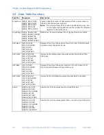
LIFO Read  


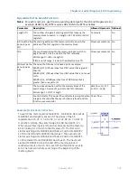
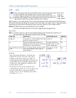
The Last-In-First-Out (LIFO) Read (LIFO_RD) function moves data out 
of tables. Values are always moved out of the top of the table. If the 
pointer reaches the last location and the table becomes full, LIFO_RD 
must be used to remove the entry at the pointer location and 
decrement the pointer by one. LIFO_RD is used in conjunction with the 
LIFO_WRT function, which increments the pointer and writes entries 
into the table. 


Mnemonics: 
LIFO_RD_DINT 
LIFO_RD_DWORD 
LIFO_RD_INT 
LIFO_RD_UINT 
LIFO_RD_WORD 

1.


LIFO_RD copies data indicated by the pointer to output parameter Q. Additional program logic 
must then be used to place the data in the input reference.  

2.


LIFO_RD decrements the pointer by one.  

3.


Steps 1 and 2 are repeated each time the instruction is executed, until the table is empty (PTR = 
LEN).  

The pointer does not wrap around when the table is full.  
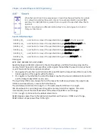
When LIFO_RD receives power flow, the data at the pointer location is copied to output Q, then the 
pointer is decremented. If this causes the pointer location to become 0, the output EM is set ON, i.e., 
EM indicates whether or not the table is empty. If the table is empty when LIFO_RD receives power 
flow, no read occurs. The pointer always indicates the last item entered into the table.  
LIFO_RD passes power to the right if the pointer was in range for an element to be read. 

Note:

  A LIFO table is a stack. A FIFO table is a queue. 

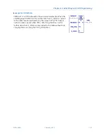
Operands for LIFO Read 

Note:

  For each mnemonic, use the corresponding data type for the TB and Q operands. For 

example, LIFO_RD_DINT requires TB and Q to be DINT variables.  

Parameter 

Description 

Allowed Operands 

Optional 

Length (??) 

 Length 

 32,767. 

Constant 

No 

TB (must be the same 
type as Q) 

The elements in the table 

All except constants 

No 

PTR 

Pointer. Index of the next 
element to read.  

All except constants, S - SC, and data flow  No 

EM 

Energized when the last 
element of the table is read 

Power flow 

No 

Q (must be the same 
type as TB) 

The element read from the 
table 

All except constants and S. SA, SB, SC 
allowed only for WORD, DWORD. 

No 

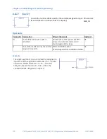
Example for LIFO Read 

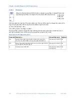
PRODUCT is a LIFO table with 100 word-sized elements. When 
the enabling input PACK_IT is ON, the data item at the top of the 
table is copied into the reference indicated by the nickname 
CART. The reference identified by STK_PTR contains the table 
pointer. Output coil EMPTY indicates when the table is empty.


Содержание PACSystems RSTi-EP

Страница 1: ...ontrols For Public Disclosure Programmable Control Products RX7i RX3i and RSTi EP CPU Programmer s Reference Manual GFK 2950C PACSystems RX7i RX3i and RSTi EP CPU Programmer s Reference Manual GFK 2950C February 2018 ...

Страница 2: ...luded herein Changes modifications and or improvements to equipment and specifications are made periodically and these changes may or may not be reflected herein It is understood that GE may make changes modifications or improvements to the equipment referenced herein or to the document itself at any time This document is intended for trained personnel familiar with the GE products referenced here...

Страница 3: ...International Americas Direct Dial 1 780 420 2010 if toll free 800 option is unavailable Customer Care Email digitalsupport ge com Primary language of support English Europe the Middle East and Africa Phone 800 1 433 2682 EMEA Direct Dial 420 296 183 331 if toll free 800 option is unavailable or if dialing from a mobile telephone Customer Care Email digitalsupport emea ge com Primary languages of ...

Страница 4: ...lication Program 6 2 1 1 Blocks 6 2 1 2 Functions and Function Blocks 6 2 1 3 How Blocks Are Called 7 2 1 4 Nested Calls 7 2 1 5 Types of Blocks 8 2 1 6 Local Data 18 2 1 7 Parameter Passing Mechanisms 19 2 1 8 Languages 21 2 2 Controlling Program Execution 24 2 3 Interrupt Driven Blocks 25 2 3 1 Interrupt Handling 26 2 3 2 Timed Interrupts 27 2 3 3 I O Interrupts 27 2 3 4 Module Interrupts 27 2 3...

Страница 5: ...unctions Handle Numerical Data 51 3 9 1 Data Types 51 3 9 2 Floating Point Numbers 53 3 10 User Defined Types UDTs 55 3 10 1 Working with UDTs 55 3 10 2 UDT Properties 55 3 10 3 UDT Limits 56 3 10 4 RUN Mode Store of UDTs 56 3 10 5 UDT Operational Notes 57 3 11 Operands for Instructions 58 3 12 Word for Word Changes 60 3 12 1 Exception Symbolic Variables 60 Chapter 4 Ladder Diagram LD Programming ...

Страница 6: ...acts 96 4 4 6 Transition Contacts 97 4 5 Control Functions 102 4 5 1 Do I O 103 4 5 2 Edge Detectors 106 4 5 3 Drum 108 4 5 4 For Loop 112 4 5 5 Mask I O Interrupt 114 4 5 6 Read Switch Position 115 4 5 7 Scan Set IO 116 4 5 8 Suspend I O 117 4 5 9 Suspend or Resume I O Interrupt 118 4 6 Conversion Functions 119 4 6 1 Convert Angles 120 4 6 2 Convert UINT or INT to BCD4 121 4 6 3 Convert DINT to B...

Страница 7: ... 4 8 9 Data Initialize Communications Request 158 4 8 10 Data Initialize DLAN 159 4 8 11 Move 160 4 8 12 Move Data 162 4 8 13 Move Data Explicit 163 4 8 14 Move From Flat 164 4 8 15 Move to Flat 166 4 8 16 Shift Register 168 4 8 17 Size Of 170 4 8 18 Swap 171 4 9 Data Table Functions 172 4 9 1 Array Move 174 4 9 2 Array Range 176 4 9 3 FIFO Read 178 4 9 4 FIFO Write 180 4 9 5 LIFO Read 182 4 9 6 L...

Страница 8: ...mer Function Blocks 217 4 13 3 Standard Timer Function Blocks 228 Chapter 5 Function Block Diagram FBD 233 5 1 Note on Reentrancy 234 5 2 Advanced Math Functions 235 5 2 1 EXPT Function 237 5 3 Bit Operation Functions 238 5 3 1 Logical AND Logical OR and Logical XOR 240 5 3 2 Logical NOT 242 5 4 Comments 243 5 4 1 Text Block 243 5 5 Comparison Functions 244 5 5 1 Equal Not Equal Greater or Equal G...

Страница 9: ...278 6 2 3 To enable Constant Sweep mode and use a new timer value 278 6 2 4 To change the timer value without changing the selection for sweep mode state 278 6 2 5 To read the current timer state and value without changing either 279 6 3 SVC_REQ 2 Read Window Modes and Time Values 280 6 4 SVC_REQ 3 Change Controller Communications Window Mode 281 6 4 1 To disable the controller communications wind...

Страница 10: ...17 Mask Unmask I O Interrupt 306 6 18 1 Masking Unmasking Module Interrupts 306 6 19 SVC_REQ 18 Read I O Forced Status 308 6 20 SVC_REQ 19 Set Run Enable Disable 309 6 21 SVC_REQ 20 Read Fault Tables 310 6 21 1 Non Extended Formats 311 6 21 2 Extended Formats 314 6 22 SVC_REQ 21 User Defined Fault Logging 319 6 23 SVC_REQ 22 Mask Unmask Timed Interrupts 321 6 24 SVC_REQ 23 Read Master Checksum 322...

Страница 11: ...quality 338 6 33 12 Redundancy 338 6 33 13 ENO and Power Flow to the Right 338 6 33 14 Parameter Block for SVC_REQ 57 339 Chapter 7 PID Built In Function Block 343 7 1 Operands of the PID Function 344 7 1 1 Operands for LD Version of PID Function Block 344 7 1 2 Operands for FBD Version of PID Function Block 345 7 2 Reference Array for the PID Function 346 7 2 1 Scaling Input and Outputs 346 7 2 2...

Страница 12: ... 2 Statement Types 368 8 2 1 Assignment Statement 369 8 2 2 Function Call 370 8 2 3 RETURN Statement 373 8 2 4 IF Statement 374 8 2 5 CASE Statement 375 8 2 6 FOR DO Statements 377 8 2 7 WHILE Statement 379 8 2 8 REPEAT Statement 380 8 2 9 ARG_PRES Statement 381 8 2 10 Exit Statement 382 Chapter 9 Diagnostics 383 9 1 Fault Handling Overview 384 9 1 1 System Response to Faults 384 9 1 2 Fault Table...

Страница 13: ...Up Group 129 416 9 4 20 Corrupted User Program on Power Up Group 130 417 9 4 21 Window Completion Failure Group 131 417 9 4 22 Password Access Failure Group 132 418 9 4 23 Null System Configuration for RUN Mode Group 134 418 9 4 24 CPU System Software Failure Group 135 419 9 4 25 Communications Failure During Store Group 137 421 9 4 26 Non Critical CPU Software Event Group 140 422 9 5 I O Fault De...

Страница 14: ...9 GBC Software Exception Category 21 441 9 5 20 Block Switch Category 22 442 9 5 21 Reset of IOC Category 27 442 9 6 Diagnostic Logic Blocks DLBs 443 9 6 1 DLB Operation 444 9 6 2 Executing DLBs 446 9 6 3 Diagnostic Logic Block DLB Example 450 ...

Страница 15: ...____________________________________ 343 Figure 15 PID in Function Block Diagram____________________________________________________________________ 343 Figure 16 PID_IND Diagram_________________________________________________________________________________ 355 Figure 17 PID Example Logic________________________________________________________________________________ 364 Figure 18 Controller Fau...

Страница 16: ...ifications see PACSystems RX7i RX3i and RSTi EP CPU Reference Manual GFK 2222 Programming Features are described in Chapter 2 through Chapter 8 Elements of an Application Program Chapter 2 Program Data Chapter 3 Ladder Diagram LD instruction set reference Chapter 4 Function Block Diagram FBD instruction set reference Chapter 5 The Service Request Function Chapter 6 The PID Function Chapter 7 Struc...

Страница 17: ...te Rack Remote Slot Remote Sub Slot and Device ID Requires RX3i firmware version 9 40 or later B Oct 2017 Added Redundancy and FA_OK System Bits S Section 3 8 1 A May 2017 Changed the document Title and the contact information Updated the Titles of the GFK s wherever applicable May 2015 PACSystems RX7i and RX3i CPU Reference Manual GFK 2222U Chapters 5 11 Chapter 14 form the content of this new ma...

Страница 18: ...xisting systems Support for existing Series 90 modules expansion racks and remote racks protects your hardware investment You can upgrade on your timetable without disturbing panel wiring The RX3i supports most Series 90 30 modules expansion racks and remote racks For a list of supported I O Communications Motion and Intelligent modules see the PACSystems RX3i System Manual GFK 2314 The RX7i suppo...

Страница 19: ...RX3i PROFIBUS Modules User s Manual GFK 2301 PACSystems RX3i Max On Hot Standby Redundancy User s Manual GFK 2409 PACSystems RX3i Ethernet Network Interface Unit User s Manual GFK 2439 PACMotion Multi Axis Motion Controller User s Manual GFK 2448 PACSystems RX3i PROFINET Scanner Manual GFK 2737 PACSystems RX3i CEP PROFINET Scanner User Manual GFK 2883 PACSystems RX3i Serial Communications Modules ...

Страница 20: ...8 5 Chapter 2 Program Organization This chapter provides information about the operation of application programs in a PACSystems CPU Structure of the Application Program Controlling Program Execution Interrupt Driven Blocks ...

Страница 21: ...k is a named section of executable logic that can be downloaded to and run on the target controller The logic in a block can include functions function blocks and calls to other blocks 2 1 2 Functions and Function Blocks A function is a type of instruction that has no internal storage instance data Therefore it produces the same result for the same set of input values every time it executes A func...

Страница 22: ...SE and resumes execution at the point after the block call instruction Note To halt the CPU when there is not enough stack space to execute a block there are two choices The best method is to add logic to detect the occurrence of any User Application Fault by testing the diagnostic bit SA38 and then call SVC_REQ 13 to halt the CPU An alternative method is to add logic that tests for a negative OK ...

Страница 23: ...ecution unless Y0 is set to FALSE within the logic of the block For all block types the maximum number of input parameters is one less than the maximum number of output parameters This is because the EN input to the block call is not considered to be an input parameter to the block It is used in LD language to determine whether or not to call the block but is not passed into the block if the block...

Страница 24: ... a parameterized block and the block is called by _MAIN L references will be inherited from the P references wherever encountered in the parameterized block for example L0005 P0005 Note It is possible by using Online Editing in the programming software to cause a parameterized block to use L higher than allowed because of the way it inherits data Using a word for word change to restore this refere...

Страница 25: ...ns on arguments relative to this general rule S memory addresses cannot be used as arguments to any output parameter This is because user logic is not allowed to write to S memory Indirect references used as arguments are resolved immediately before the parameterized block is called and the corresponding direct reference is passed into the block For example where R1 contains the value 10 and R1 is...

Страница 26: ...B to the next Note A member variable is not passed into or out of a UDFB as a parameter A member variable is used only within the logic of that function block A UDFB cannot be triggered by an interrupt UDFB logic is created using FBD LD or ST UDFB logic can make calls to all the other types of PACSystems blocks blocks parameterized blocks external blocks and other UDFBs Blocks parameterized blocks...

Страница 27: ...UDFB named Motors Each instance variable has elements corresponding to parameters In1 Out1 and Y0 and internal variables modelno speed and temp Instances are created as symbolic variables never as mapped variables This ensures that instance data is only referenced by the instance name and not by a memory address which means that no aliases can be created for the UDFB data elements The indirect ref...

Страница 28: ... 1 to 1024 INPUTS by reference constant reference value or value result Default value Retentive for value or value result Not applicable for reference OUTPUTS by result INT UINT and WORD 1 to 512 INPUTS by reference constant reference value or value result Default value Retentive for value or value result Not applicable for reference OUTPUTS by result DINT REAL and DWORD 1 to 256 INPUTS by referen...

Страница 29: ...a UDFB type does not create an instance A nested instance cannot be of the same type as the UDFB being defined because this would set up an infinitely recursive definition Nor can any level of a nested instance be of the same type as the parent UDFB being defined For example the UDFB Motor cannot have an internal variable of type Valve if the Valve UDFB contains an internal variable of type Motor ...

Страница 30: ...s an argument to a parameterized block can be invoked by the parameterized block s logic The output parameters and their corresponding instance data elements of a UDFB instance that is passed as an argument can be read but not modified by the receiving block s logic The input parameters of a UDFB instance that is passed as an argument cannot be read or modified by the receiving block s logic The i...

Страница 31: ...lock is called by _MAIN L references will be inherited from the P references wherever encountered in the external block for example L0005 P0005 Initialization of C Variables When an external block is stored to the CPU a copy of the initial values for its global and static variables is saved However if static variables are declared without an initial value the initial value is undefined and must be...

Страница 32: ...T UINT and WORD 1 to 512 INPUTS by reference OUTPUTS by reference DINT REAL and DWORD 1 to 256 INPUTS by reference OUTPUTS by reference LREAL 1 to 128 INPUTS by reference OUTPUTS by reference UDT3 1 to 128 INPUTS by reference OUTPUTS not allowed The PACSystems default parameter passing mechanisms correspond to the way that external block parameters are passed on 90 70 controllers The parameter pas...

Страница 33: ...ata as well as the P data that is available to all blocks The _MAIN block cannot use L External blocks and parameterized blocks can use the Local Data L of their calling block as well as the P data of the _MAIN block If a parameterized block or external block is called by MAIN all L references in the parameterized block or external block will actually be references to corresponding P references fo...

Страница 34: ...sed by constant reference the CPU passes a reference address pointer symbolic variable pointer or I O variable pointer into the function block instance or parameterized block The instance or block can only read the reference address or variable When a parameter is passed by friend UDFB inputs only the CPU passes a UDFB instance variable pointer into the function block instance or parameterized blo...

Страница 35: ...ith the called block and the address of its argument is saved All logic within the called block that reads or writes to the parameter is reading or writing to this stack memory When the called block completes its execution the value in the stack memory is copied back to the actual argument s address Thus no changes are made to the actual argument while the called block is executing but when it com...

Страница 36: ...memory location contains the value 1 The same relay passes negative power flow if the memory location contains the value 0 Usually an instruction that receives negative power flow does not execute and propagates the negative power flow on to the next instruction in the rung However some instructions such as timers and counters execute even when they receive negative power flow and may even pass po...

Страница 37: ...struction in the FBD editor b Whether the inputs to the FBD instruction are resolved To determine the order of execution of FBD instructions in the FBD editor the FBD compiler performs the following steps 1 The FBD compiler scans the instructions in the FBD editor beginning from left to right and top to bottom When an instruction is encountered the compiler attempts to resolve the instruction that...

Страница 38: ...atement directs the PLC to perform a specified action Statements provide variable assignments conditional evaluations iteration and the ability to call other blocks For details on ST statements parameters keywords and operators supported by PACSystems refer to Structured Text ST Programming in Chapter 8 Blocks parameterized blocks and UDFBs can be programmed in ST The _MAIN program block can also ...

Страница 39: ... blocks The nested Master Control Relay MCRN function can be used to execute a portion of the program logic with negative power flow Logic is executed in a forward direction and coils in that part of the program are executed with negative power flow Master Control Relay functions can be nested to 255 levels deep The Suspend I O function can be used to stop both the input scan and output scan for o...

Страница 40: ...discrete input state changes rising falling edge analog range limits low high alarms and high speed signal counting events Module Interrupts are generated by VME modules A single interrupt is supported per module Caution Interrupt driven block execution can interrupt the execution of non interrupt driven logic Unexpected results may occur if the interrupting logic and interrupted logic access the ...

Страница 41: ...n blocks do not accumulate time if used in a block that is executed as a result of an interrupt Blocks that are triggered by interrupts can make calls to other blocks The application stack used during interrupt driven execution is different from the stack used during normal block structured program execution In particular the nested call limit is different from the limit described for calls from t...

Страница 42: ...put Module IC697MDL650 the first input can be configured to generate an interrupt on either the rising or falling edge of the input signal If the interrupt is enabled in the module configuration that input can serve as a trigger to cause the execution of a block To configure an I O interrupt specify a trigger in the scheduling properties for the block The trigger must be a global variable in I AI ...

Страница 43: ...or this block are ignored Preemptive Block Scheduling Preemptive scheduling allows you to assign a priority to each interrupt trigger The priority values range from 1 to 16 with 1 being the highest A single block can have multiple interrupts with different priorities or the same priorities An incoming interrupt is handled according to its priority compared to that of the currently executing block ...

Страница 44: ...ns how that data is stored in the PACSystems CPU s memory Variables Reference Memory User Reference Size and Default Genius Global Data Transitions and Overrides Retentiveness of Logic and Data Data Scope System Status References How Program Functions Handle Numerical Data User Defined Types UDTs Operands for Instructions Word for Word Changes ...

Страница 45: ...umbers with no fractional part Data types are described in How Program Functions Handle Numerical Data In the programming software all variables in a project are displayed in the Variables tab of the Navigator You create edit and delete variables in the Variables tab Some variables are also created automatically by certain components such as TIMER variables when you add a Timer instruction to ladd...

Страница 46: ...ymbolic variables cannot be used with indirect references for example Name For a full description refer to Indirect References Only global scope Symbolic variables can be used in EGD pages A variable must be globally scoped and published internal or external to be used in a C block Symbolic variables cannot be used in the COMMREQ status word Use of symbolic variables is not supported on web pages ...

Страница 47: ...and logic independently When the HWC and logic are coupled in the PACSystems controller you cannot clear the HWC and the logic independently As for any download you cannot RUN Mode Store RMS the HWC and logic independently The HWC must be completely equal for you to make word for word changes launch the Online Test mode of Test Edit or accept the edits of Test Edit I O variables can be used any pl...

Страница 48: ... of elements in array BYTE variable 8 BYTE array 8n where n is the number of array elements W DINT variable 2 DINT array Number of elements in array times 2 DWORD variable 2 DWORD array Number of elements in array times 2 INT variable 1 INT array Number of elements in array LREAL variable 4 LREAL array Number of elements in array times 4 REAL variable 2 REAL array Number of elements in array times...

Страница 49: ...of the variable is evaluated and the corresponding array element is accessed Note The numbering of array elements is zero based For example to access an element of the array named ABC you could write ABC DEF in logic When logic is executed if the value of DEF is 5 then ABC DEF is equivalent to ABC 5 and the sixth element of array ABC is accessed If the value of the variable index exceeds the array...

Страница 50: ...onstant with an index variable In LD Diagnostic Logic Blocks support the use of array elements with variable indexes Where Array Elements with Variable Indexes are Not Supported The following do not support array elements with variable indexes Indirect references EGD variables Reference ID variables RIVs and I O variables when accessed in the Hardware Configuration Note In logic RIVs and I O varia...

Страница 51: ... that uses a variable index compare the value of the index variable with the number of elements in the array Tip In LD use a RANGE instruction Notes Checking before executing each instruction that uses an indexed variable is recommended in case logic has modified the index value beyond the array size or in case the array size has been reduced before the scan to less than the value of an index vari...

Страница 52: ...erences are retained across a power cycle to the CPU Indirect References An indirect reference allows you to treat the contents of a variable assigned to an LD instruction operand as a pointer to other data rather than as actual data Indirect references are used only with word memory areas R W AI AQ P and L An indirect reference in W requires two W locations as a DWORD indirect index value For exa...

Страница 53: ...BIT IN ST and Q Restrictions The use of Bit in Word references has the following restrictions Bit in Word references cannot be used on legacy transition contacts POSCON NEGCON and transition coils POSCON NEGCON The bit number index must be a constant it cannot be a variable Bit addressing is not supported for a constant Indirect references cannot be used to address bits in 16 bit memory You cannot...

Страница 54: ...s temporary references These references are never checked for multiple coil use and can therefore be used many times in the same program even when coil use checking is enabled this is not a recommended practice because it makes subsequent trouble shooting more difficult T may be used to prevent coil use conflicts while using the cut paste and file write include functions Because this memory is int...

Страница 55: ...l Reference Words 0 maximum available user RAM 1152 words L per block 8192 words 8192 words P per program 8192 words 8192 words Managed Memory Symbolic Discrete 0 83 886 080 bits 32768 Symbolic Non Discrete 0 5 242 880 words 65536 I O Discrete 0 through 83 886 080 0 I O Non Discrete 0 through 5 242 880 0 Total Symbolic 0 42 088 704 bytes This is the total memory available for the combined total of...

Страница 56: ...or the automatic and repeated transfer of G I Q AI AQ and R data No special application programming is required to use global data since it is integrated into the I O scan All devices that have Genius I O capability can send and receive global data from a PACSystems CPU Using I O Variables you can directly associate variable names to a module s Genius global data that is scanned as part of an inpu...

Страница 57: ...ten to the reference is the same as the previous value of the reference Therefore when a reference is written and its new value is the same as its previous value its transition bit is turned OFF When its new value is different from its previous value its transition bit is turned ON The transition bit for a reference is affected every time the reference is written to The source of the write is imma...

Страница 58: ...re not saved on STOP Mode to RUN Mode transitions symbolic variables that have a data type other than BOOL symbolic variables of BOOL type that are configured as retentive Retentive data is also preserved during power cycles of the CPU with battery backup or Energy Pack backup Exceptions to this rule include the fault locating references and most of the S SA SB and SC references These references a...

Страница 59: ... in these registers Symbolic variable Global From any program block or host computer Symbolic variables have system global scope by default However symbolic variables with local scope can be created using the naming conventions for local variables I O variable Global From any program block or host computer P Program From any block but not from other programs also available to a host computer L Loc...

Страница 60: ...MIN Examples of other system status references include FST_SCN ALW_ON and ALW_OFF Note S bits are read only bits do not write to these bits However you can write to SA SB and SC bits Listed below are available system status references that can be used in an application program When entering logic either the reference or the nickname can be used Refer to Chapter 9 for detailed fault descriptions an...

Страница 61: ...during operation this contact is set to 1 If used in conjunction with a legacy non smart battery this indication is not reliable Battery less CPUs including CPE302 CPE305 CPE310 and CPE330 Energy Pack is connected and functioning 0 Energy Pack is not connected or has failed 1 S0033 PRI_UNT Set to 1 if the local unit is configured as the Primary CPU otherwise it is cleared For any given local unit ...

Страница 62: ... For details refer to Battery Status Group 18 in Chapter 9 The CPU may set this contact when an I O module or special purpose module has reported a low battery In this case a fault will be reported in the I O Fault Table To clear this bit clear the CPU fault table or power cycle the CPU SA0012 LOS_RCK Set when an expansion rack stops communicating with the CPU To clear this bit clear the CPU fault...

Страница 63: ...hen the CPU is power cycled SB0012 NUL_CFG Set when an attempt is made to put the CPU in RUN Mode when there is no configuration data present To clear this bit clear the CPU fault table or power cycle the CPU SB0013 SFT_CPU Set when the CPU detects an error in the CPU operating system software To clear this bit clear the CPU fault table or power cycle the CPU SB0014 STOR_ER Set when an error occur...

Страница 64: ...e fault Configurable Fault References Configurable Faults Default Action Description SBUS_ER diagnostic System bus error The BSERR signal was generated on the VME system bus SFT_IOC diagnostic Non recoverable software error in a Genius Bus Controller LOS_RCK diagnostic Loss of rack BRM failure loss of power or missing a configured rack LOS_IOC diagnostic Loss of Bus Controller missing a configured...

Страница 65: ... the module APL_FLT diagnostic Application fault ADD_RCK diagnostic New rack added extra or previously faulted rack has returned ADD_IOC diagnostic Extra I O Bus Controller or reset of I O Bus Controller ADD_IOM diagnostic Previously faulted I O module is no longer faulted or extra I O module ADD_SIO diagnostic New intelligent option module is added extra or reset NO_PROG information No applicatio...

Страница 66: ...T data type is 32768 to 32767 Register 1 Two s Complement value 16 1 S s sign bit 0 positive 1 negative DINT Double Precision Integer Stored in 32 bit data memory locations two consecutive 16 bit memory locations Always signed values bit 32 is the sign bit The valid range of a DINT data type is 2147483648 to 2147483647 s sign bit 0 positive 1 negative REAL Floating Point Uses 32 consecutive bits t...

Страница 67: ...duces a double integer result The DIV function takes a double integer dividend and an integer divisor to product an integer result ASCII ASCII Eight bit encoded characters A single word reference is required to make two packed ASCII characters The first character of the pair corresponds to the low byte of the reference word The remaining 7 bits in each section are converted Note Using functions th...

Страница 68: ...7x10308 Note The programming software allows 32 bit and 64 bit arguments DWORD DINT REAL and LREAL to be placed in discrete memories such as I M and R in the PACSystems target This is not allowed on Series 90 70 targets Note that any bit reference address that is passed to a non bit parameter must be byte aligned This is the same as the Series 90 70 CPU Internal Format of REAL Numbers 16 1 32 17 8...

Страница 69: ...oduced by overflow are used as operands to other REAL or LREAL functions they may cause an undefined result This undefined result is referred to as an NaN Not a Number For example the result of adding positive infinity to negative infinity is undefined When the ADD_REAL function is invoked with positive infinity and negative infinity as its operands it produces an NaN If any operand of a function ...

Страница 70: ...gic 3 10 2 UDT Properties Name The UDT s name Maximum length 32 characters Description The user defined description of the UDT Memory Type The type of symbolic or I O variable memory in which a variable of this UDT resides Non Discrete Default Word oriented memory organized in groups of 16 contiguous bits Discrete Bit oriented memory Notes You cannot nest a UDT of one memory type in a UDT of a dif...

Страница 71: ...ory type You cannot alias a variable to a UDT variable or UDT variable element A FAULT contact supports a BOOL element of a UDT I O variable but not a BOOL element of a UDT parameter in a UDFB or parameterized block POSCON and NEGCON do not support BOOL elements of UDT parameters in parameterized blocks or UDFBs 3 10 4 RUN Mode Store of UDTs An RMS can be performed on a target that contains a vari...

Страница 72: ...ta types and sequence 2 Create an array of length 6 named ABC of the COMMREQ6 data type 3 The array resides in symbolic memory You can convert the symbolic variable to an I O variable 4 Populate the variable If the value of an element needs to be the same for all six COMMREQ6 elements you can set up an ST for loop that uses a variable index to populate each element with the same data for example f...

Страница 73: ... some input parameters of some functions This occurs when the function during the course of its execution actually writes a value to the input parameter Data flow is prohibited in these cases because data flow is stored in a temporary memory and any updated value assigned to it would be inaccessible to the user application The arguments to EN OK and many other BOOLEAN input and output parameters a...

Страница 74: ...ement of the BOOL array must be 8n 1 where n 0 1 2 3 and so on For example M00033 is byte aligned because 33 8 4 1 The parameter in question must support discrete memory reference addresses The instruction in question must not have a Length parameter The Length parameter is displayed as in the LD editor until a value has been assigned The data type to be replaced with a BOOL array must be one of t...

Страница 75: ...amples include changing the type of contact or coil or changing a reference address used for an existing function block The following are word for word changes Switching between two symbolic variables Switching between a symbolic variable and a mapped variable Switching between a constant and a symbolic variable 3 12 1 Exception Symbolic Variables Creating deleting or modifying a symbolic variable...

Страница 76: ...ing categories Advanced Math Functions Bit Operation Functions Coils Contacts Control Functions Conversion Functions Counters Data Move Functions Data Table Functions Math Functions Program Flow Functions Relational Functions Timers Motion Functions and Function Blocks RX3i CPUs support PLCopen compliant motion functions and function blocks Details of these function blocks can be found in the PACM...

Страница 77: ...angent of the IN operand and expresses the result in radians Logarithmic LN_REAL LN_LREAL Calculates the natural logarithm of the operand IN LOG_REAL LOG_LREAL Calculates the base 10 logarithm of the operand IN Square Root SQRT_DINT Calculates the square root of the operand IN a double precision integer and stores in Q the double precision integer portion of the square root of the input IN SQRT_IN...

Страница 78: ...m of IN The power flow output is energized when the function is performed unless Overflow or one of the following invalid conditions occurs IN 0 for LOG or LN IN1 0 for EXPT IN is negative infinity for EXP IN IN1 or IN2 is a NaN Not a Number Operands of the Exponential Logarithmic Functions Parameter Description Allowed Operands Optional IN or IN1 For EXP LOG and LN IN contains the REAL or LREAL v...

Страница 79: ...formed without Overflow unless one of these invalid REAL operations occurs If IN 0 Q is set to 0 and ENO is set FALSE If IN is a NaN Not a Number Q will also be a NaN value and ENO will be set false Example The square root of the integer number located at AI0001 is placed into R00003 when I00001 is ON Operands for the Square Root Function Parameter Description Allowed Operands Optional IN The valu...

Страница 80: ...lt in output Q The SIN COS and TAN functions accept a broad range of input values where 263 IN 263 263 is approximately 9 22x1018 Input values outside this range will produce incorrect results The power flow output is energized unless the following invalid condition occurs IN or Q is a NaN Not a Number Operands of Trig Functions Parameter Description Allowed Operands Optional IN Number of radians ...

Страница 81: ...produces a result Q such that 2 π Q 2 π ASIN IN The ACOS function produces a result Q such that π Q 0 ACOS IN The ATAN function accepts the broadest range of input values where IN Given a valid value for the IN parameter the ATAN function produces a result Q such that 2 π Q 2 π ATAN IN The power flow output is energized unless one of the following invalid conditions occurs IN is outside the valid ...

Страница 82: ...al invert Sets the state of each bit in output bit string Q to the opposite state of the corresponding bit in bit string IN1 Logical OR OR_DWORD OR_WORD Compares the bit strings IN1 and IN2 bit by bit When a pair of corresponding bits are both 0 places a 0 in the corresponding location in output string Q otherwise places a 1 in the corresponding location in Q Logical XOR XOR_DWORD XOR_WORD Compare...

Страница 83: ...t 1 of the first WORD or DWORD being the Least Significant Bit LSB The last bit of the last WORD or DWORD is the Most Significant Bit MSB For example if you specify three WORDs of data beginning at reference R0100 they are treated as 48 contiguous bits Warning Overlapping input and output reference address ranges in multiword functions is not recommended as it can produce unexpected results Note t...

Страница 84: ...t Position Parameter Description Allowed Operands Optional Length displayed as The number of WORDs or DWORDs in the bit string 1 Length 256 Constants No IN The data to operate on All Constants may only be used when Length is 1 No Q Energized if a bit set to 1 is found Flow Yes POS An unsigned integer giving the position of the first nonzero bit found or zero if no non zero bit is found All except ...

Страница 85: ... is not active and the previous EN was OFF the bit pointed to by the current step number is cleared The current step number is incremented or decremented based on the direction DIR operand Then the bit pointed to by the new step number is set to 1 When the step number is being incremented and it goes outside the range of 1 step number Length it is set back to 1 When the step number is being decrem...

Страница 86: ...perands for Bit Sequencer Warning Do not write to the Control Block memory with other instructions Overlapping references may cause erratic operation of BIT_SEQ Parameter Description Allowed Operands Optional Address Beginning address of the Control Block which is a three word array Word 1 current step number Word 2 length of sequence in bits Word 3 control word which tracks the status of the last...

Страница 87: ...T is in M memory and the Length is 3 the bit sequencer occupies 3 bits the other 5 bits of the byte are not used If ST is in R memory and the Length is 17 the bit sequencer uses 4 bytes all of R1 and R2 All except constants flow and variables located in S Yes Example In the following example a FST_SCN system variable is used to set CLEAR to ON for one scan This sets the step number in Word 1 of th...

Страница 88: ...fected The function passes power flow to the right unless the value for BIT is outside the specified range Operands for Bit Set Bit Clear Parameter Description Allowed Operands Optional Length The number of WORDs or DWORDs in the bit string 1 Length 256 Constants No IN The first WORD or DWORD of the data to process All except constants flow and variables located in S No BIT The number of the bit t...

Страница 89: ... the bits are numbered 1 through 16 for a WORD not 0 through 15 They are numbered 1 through 32 for a DWORD Operands for Bit Test Parameter Description Allowed Operands Optional Length The number of WORDs or DWORDs in the data string to test 1 Length 256 Constant No IN The first WORD or DWORD in the data to test All No BIT The number of the bit to test in IN 1 BIT 16 Length All except variables loc...

Страница 90: ... combine strings or to control many outputs with one simple logical structure The Logical OR function is the equivalent of two relay contacts in parallel multiplied by the number of bits in the string You can use the Logical OR function to drive indicator lamps directly from input states or to superimpose blinking conditions on status lights Logical XOR When the Exclusive OR XOR function receives ...

Страница 91: ...operate on All No IN2 Must be the same data type as IN1 The first WORD or DWORD of the second string to operate on All No Q Must be the same data type as IN1 The first WORD or DWORD of the operation s result All except constants and variables located in S memory No Example Logical AND When input v_I0001 is set the 16 bit strings represented by variables WORD1 and WORD2 are examined The logical AND...

Страница 92: ... whenever it receives power You can specify a string length of 1 to 256 WORDs or DWORDs Operands for Logical NOT Parameter Description Allowed Operands Optional Length The number of WORDs or DWORDs in the bit string to NOT 1 Length 256 Constant No IN1 The first WORD or DWORD of the input string to NOT All No Q Must be the same data type as IN1 The first WORD or DWORD of the NOT s result All except...

Страница 93: ... at the next bit position after a miscompare or if all bits compared successfully upon the next invocation of the function the compare starts at the beginning Tip If you want to start the next comparison at some other location in the string you can enter different references for BIT and BN If the value of BIT is a location that is beyond the end of the string BIT is reset to 0 before starting the ...

Страница 94: ...in S SC memories No Q The output copy of the compare mask bit string All except constants No BN The number of the bit where the latest miscompare occurred or the highest bit number in the inputs if no miscompare occurred All except constants and variables in S memory No MC Can be used to determine if a miscompare has occurred flow Yes Masked Compare Example 1 When I00001 is set MASK_COMP_WORD comp...

Страница 95: ...utes M0001 through M0016 is compared with M0017 through M0032 M0033 through M0048 contains the mask value The value in R0001 determines the bit position in the two input strings where the comparison starts Before the function is executed the contents of the above references are The FST_SCN contact forces one and only one execution otherwise the function would repeat with possibly unexpected result...

Страница 96: ...ng to be rotated the output parameter Q must use the same memory location as the input parameter IN The entire rotated string is written on each scan that power is received A string length of 1 to 256 words or double words can be specified Operands for Rotate Bits Parameter Description Allowed Operands Optional Length The number of WORDs or DWORDs in the string to be rotated 1 Length 256 Constant ...

Страница 97: ... to the right As bits are shifted out of the low end of the string LSB the same number of bits is shifted in at the high end MSB Shift Left and Shift Right A string length Length of 1 to 256 words can be specified The bits being shifted into the beginning of the string are specified via input parameter B1 If the value of N is greater than 1 each bit is filled with the same value 0 or 1 This can be...

Страница 98: ...of bits in the string Length all bits in Q are set to the value B1 OK is set FALSE and B2 is set to B1 All except variables in S SC memories No B1 The bit value to shift into the array flow No B2 The bit value of the last bit shifted out of the array flow Yes Q Must be the same data type as IN The first WORD or DWORD of the shifted array All except constants and variables in S memory No Example Wh...

Страница 99: ... followed by a continuation contact at the beginning of any rung following the continuation coil Coils are always located at the rightmost position of a line of logic 4 3 1 Coil Checking The level of coil checking is set to Show as error by default If you want a coil conflict to result in a warning instead of this error or if you want no warning at all edit the Controller option Multiple Coil Use ...

Страница 100: ...e PLC to continue the present rung s LD logic power flow value TRUE or FALSE at the continuation contact on a following rung The flow state of the continuation coil is passed to the continuation contact Notes If the flow of logic does not execute a continuation coil before it executes a continuation contact the state of the continuation contact is no flow FALSE The continuation coil and the contin...

Страница 101: ... not receive power flow it does not change the value of its discrete reference Therefore whether or not the coil itself continues to receive power flow the reference stays ON until the reference is reset by other logic such as a RESET coil When a RESET coil receives power flow it resets a discrete reference to OFF When a RESET coil does not receive power flow it does not change the value of its di...

Страница 102: ...xternal device Doing so will destroy the coil s one shot nature and the coil may not behave as described Do not use a transition contact with the same reference address used on a transition coil because the value of the transition bit which stores the power flow value into the coil will be affected Positive Transition Coil POSCOIL Negative Transition Coil NEGCOIL If the transition bit is OFF and t...

Страница 103: ...t apply to POSCOILs and NEGCOILs do not apply to PTCOILs and NTCOILs Warning PTCOIL and NTCOIL instructions should not be used in a parameterized block or user defined function block UDFB with a parameter or member In these cases an R_TRIG or F_TRIG should be used instead The transition bit of a given PTCOIL or NTCOIL is changed only once per CPU scan Therefore using a PTCOIL or NTCOIL in a block ...

Страница 104: ... Multiple instances of PTCOIL and or NTCOIL can be associated with the same BOOL variable but the transition status of each instance of the PTCOIL or NTCOIL associated with the BOOL variable is unique that is it is tracked independently The transition bit is non retentive that is it is cleared to OFF when the CPU transitions from STOP Mode to RUN Mode As a result the first time a PTCOIL executes w...

Страница 105: ...r of the PTCOIL is not affected by the presence of the fourth rung which also writes to Xsition PTCOIL behaves the same way when the fourth rung is removed POSCOIL If a POSCOIL is used in place of the PTCOIL in the example below keeping the rest of the logic identical and same alternation of power flow into the POSCOIL the behavior of the logic will be different The behavior of the POSCOIL is affe...

Страница 106: ...e high alarm bit associated with the analog WORD reference is ON Low Alarm Contact LOALR if the low alarm bit associated with the analog WORD reference is ON No Fault Contact NOFLT if its associated BOOL or WORD variable does not have a point fault Normally Closed Contact NCCON if associated BOOL variable is OFF Normally Open Contact NOCON if associated BOOL variable is ON Transition Contacts NEGC...

Страница 107: ...uation contact has no associated variable Notes If the flow of logic does not execute a continuation coil before it executes a continuation contact the state of the continuation contact is no flow The state of the continuation contact is cleared set to no flow each time a block begins execution The continuation coil and the continuation contact do not use parameters and do not have associated vari...

Страница 108: ...slot bus module fault locating system variable with a FAULT NOFLT contact Note The fault indication of a given module is cleared when the associated fault is cleared from the fault table For I O point fault reporting you must enable point fault references in Hardware Configuration FAULT passes power flow if its associated variable or location has a point fault Operands Parameter Description Allowe...

Страница 109: ...PU configuration A high alarm contact passes power flow if the high alarm bit associated with the analog reference is ON The low alarm contact LOALR detects a low alarm associated with an analog reference Use of this contact must be enabled during CPU configuration A low alarm contact passes power flow if the low alarm bit associated with the analog reference is ON Operands Parameter Description A...

Страница 110: ... address I Q AI AQ with the FAULT NOFLT contacts To locate a fault use the rack slot bus module fault locating system variables with a FAULT NOFLT contact For I O point fault reporting you must configure your Hardware Configuration HWC to enable the PLC point faults Note The fault indication of a given module is cleared when the associated fault is cleared from the fault table Operands Parameter D...

Страница 111: ...ON true 1 Operands Parameter Description Allowed Operands Optional BOOLV BOOLV may be a predefined system variable or a user defined variable NCCON If BOOLV is ON the normally closed contact does not pass power flow If BOOLV is OFF the contact passes power flow discrete variables in I Q M T S SA SB SC and G memories symbolic discrete variables bit in word references on variables in any non discret...

Страница 112: ...d not be used in a parameterized block or user defined function block UDFB with a parameter or member In these cases an R_TRIG or F_TRIG should be used instead Do not use POSCON or NEGCON transition contacts for references used with transition coils also called one shot coils or with SET and RESET coils If a SETCOIL or RESETCOIL receives positive power flow and its associated variable is not overr...

Страница 113: ...ferent intervals within the Controller scan multiple times during a Controller scan resulting in the transition bit being ON for only a portion of the scan several Controller scans apart resulting in the transition bit being ON for more than one scan once per scan for example if the POSCON or NEGCON s associated variable is a I input bit The source of the write is immaterial it can be an output co...

Страница 114: ...n to again causing the NEGCON to stop passing power flow POSCON and NEGCON Example 2 Bit M00017 is set by a BIT_SET function and then cleared by a BIT_CLR function The positive transition contact X1 activates the BIT_SET and the negative transition X2 activates the BIT_CLR The positive transition associated with bit M00017 will be on until M00017 is reset by the BIT_CLR function This occurs becaus...

Страница 115: ...he following conditions are met The input power flow to NTCON is ON The value of the BOOL variable associated with NTCON is OFF The transition bit associated with the NTCON is ON The transition bit depends on the value of the BOOL variable associated with this PTCON or NTCON when it was last executed Notes As soon as a PTCON or NTCON is set to ON or OFF it updates its transition bit Multiple insta...

Страница 116: ...sweep On all other sweeps the PTCON instruction does not pass power flow POSCON If a POSCON is used in place of the PTCON in the following example keeping the rest of the logic identical the same alternation of the Xsition variable s value occurs The POSCON instruction passes power flow on sweeps 2 3 and 4 then again on sweeps 8 9 and 10 and so forth The POSCON s behavior is dependent on Xsition s...

Страница 117: ...LOOP instruction and END_FOR instruction a specified number of times or until EXIT_FOR is encountered Mask I O Interrupt MASK_IO_INTR Mask or unmask an interrupt from an I O module when using I O variables If not using I O variables use SVC_REQ 17 Mask Unmask I O Interrupt described in Chapter 6 Proportional Integral Derivative Control PID_ISA PID_IND Provides two PID Proportional Integral Derivat...

Страница 118: ...d on the I O modules Program execution then returns to the function that follows the DO_IO If the range of references includes an option module HSC APM etc all the input data I and AI or all the output data Q and AQ for that module are scanned The ALT parameter is ignored while scanning option modules DO_IO passes power to the right whenever it receives power unless Not all references of the type ...

Страница 119: ...reference is automatically calculated from the length of the END ST range Operands Parameter Description Allowed Operands Optional ST The starting address of the set of input or output points or words to be serviced ST and END must be in the same memory area If ST and END are placed in BOOL memory ST must be byte aligned That is its reference address must start at 8n 1 for example I01 Q09 Q49 If S...

Страница 120: ...puts are not updated This allows the current values of inputs to be compared with their values at the beginning of the scan This form of DO_IO allows input points to be scanned one or more times during the program execution portion of the CPU scan Example Do I O for Outputs Because a reference is entered for ALT the values at AQ001 004 are not written to output modules When DO_IO receives power fl...

Страница 121: ...ance data that can be a member or an input of the function block so that the transition state follows that of the function block instance and not the function block If an edge detector function block is used within a UDFB its instance data must be a member variable of the UDFB Operands Parameter Description Allowed Operands Optional Instance data for function block This is a structure variable des...

Страница 122: ... When the CLK input transitions from false to true the output Q is true for one function block execution The output Q then remains false until a new rising edge is detected When the Controller transitions from STOP Mode to RUN Mode and the CLK input is true and the instance memory is non retentive the output Q is set to true after the function block s first execution After the second execution the...

Страница 123: ...timers Therefore special care must be taken when programming Drum in parameterized blocks Drum functions in parameterized blocks can be programmed to track true real time as long as the guidelines and rules below are followed If the guidelines and rules described here are not followed the operation of the Drum function in parameterized blocks is undefined Note These rules are not enforced by the p...

Страница 124: ... except the _MAIN block which has a P memory area instead When the _MAIN block calls another block the P mappings from the _MAIN block are accessed by the called block as L mappings If you use a parameterized block formal parameter word array passed by reference the actual parameter that corresponds to this formal parameter must be a L R P W or symbolic reference If the actual parameter is a R P W...

Страница 125: ...trol Block Then the function copies the value in the Preset Step reference to the Q reference bits When R is active the function ignores S flow No PTN Pattern The starting address of an array of words The number of words is specified by the Length operand Each word represents one step of the Drum Sequencer The value of each word represents the desired combination of outputs for a particular value ...

Страница 126: ... has been in a particular step longer than the step s specified Fault Timeout All except S and constant Yes FF First Follower The starting address of Length 8 1 bytes of memory where Length is the number of steps If MOD Length 8 1 0 FF has Length 8 1 bytes Each bit in the bytes of FF corresponds to one word of PTN No more than one bit in the FF bytes is ON at any time and that bit corresponds to t...

Страница 127: ...by setting the increment to a negative number For example if the START value is 21 the END value is 1 and the increment value is 5 the statements of the FOR loop are executed five times and the index variable is decremented by 5 in each pass The values of the index variable will be 21 16 11 6 and 1 When the START and END values are set equal the statements of the FOR loop are executed only once Wh...

Страница 128: ...is 1 and the value for M00017 END is 10 The INDEX R00001 increments by the value of the INC operand which is assumed to be 1 when omitted starting at 1 until it reaches the ending value 10 The ADD function of the loop is executed 10 times adding the current value of I1 R00001 which will vary from 1 to 10 to the value of I2 R00002 For Loop Example 2 The value for T00001 START is 100 and the value f...

Страница 129: ...er Description Allowed Types Allowed Operands Optional MASK Selects unmask or mask operation Unmask 0 Mask 1 BOOL variable or Bit reference in non discrete memory data flow I Q M T G S SA SB SC R P L AI AQ W symbolic I O variable No IN1 The interrupt trigger to be masked or unmasked The I O board must be a supported input module The reference address specified must correspond to a valid interrupt ...

Страница 130: ... Allowed Operands Optional POS Memory location at which to write current switch position value 1 RUN I O Enabled 2 RUN Outputs Disabled 3 STOP Mode All except S SA SB SC No MODE Memory location to which switch configuration value is written 0 Switch configuration not supported 1 Switch controls RUN STOP mode 2 Switch not used or is used by the user application 3 Switch controls both memory protect...

Страница 131: ...he inputs will be scanned BOOL variable or bit reference in a non BOOL variable Power flow No OUT If true the outputs will be scanned BOOL variable or bit reference in a non BOOL variable Power flow No SET Number of the scan set to be scanned Scan sets are specified in the CPU hardware configuration and assigned to modules in the module hardware configuration UINT All except S memory types No ENO ...

Страница 132: ...o stop I O scans then cause certain I O to be scanned from the program Inputs I00010 and I00011 form a latch circuit with the contact from M00001 This keeps the SUS_IO function active on each sweep until I00011 goes on If this input were not scanned by DO_IO after SUS_IO went active SUS_IO could only be disabled by powering down the PLC Output Q00002 is set when both DO_IO functions execute succes...

Страница 133: ...nnel does not have its interrupt enabled in the configuration Operands Parameter Description Allowed Types Allowed Operands Optional SUSP Selects a suspend or resume operation 1 ON suspend 0 OFF resume BOOL variable or bit reference in a non BOOL variable data flow I Q M T G S SA SB SC R P L discrete symbolic I O variable No IN1 The interrupt trigger to be suspended or resumed BOOL or WORD variabl...

Страница 134: ...EAL to INT Convert to UINT 16 bit unsigned integer BCD4_TO_UINT Converts BCD4 to UINT INT_TO_UINT Converts INT to UINT DINT_TO_UINT Converts DINT to UINT REAL_TO_UINT Converts REAL to UINT Convert to DINT 32 bit signed integer BCD8_TO_DINT Converts 8 digit Binary Coded Decimal BCD8 to DINT UINT_TO_DINT Converts UINT to DINT INT_TO_DINT Converts INT to DINT REAL_TO_DINT Converts REAL 32 bit signed ...

Страница 135: ...on receives power flow it performs the appropriate angle conversion on the REAL or LREAL value in input IN and places the result in output Q DEG_TO_RAD and RAD_TO_DEG pass power flow to the right when they execute unless IN is NaN Not a Number Operands Parameter Description Allowed Operands Optional IN The value to convert All except S SA SB and SC No Q The converted value All except S SA SB and S...

Страница 136: ...plays or presets to external devices such as high speed counters Operands Parameter Description Allowed Operands Optional IN The UINT or INT value to convert to BCD4 All except S SA SB and SC No Q The BCD4 equivalent value of the original UINT or INT value in IN All except S SA SB and SC No Example UINT to BDC4 Whenever input I00002 is set and no errors exist the UINT at input location I00017 thro...

Страница 137: ...ectly as input for another program function The function passes power flow when power is received unless the conversion would result in a value that is outside the range 0 to 99 999 999 Operands Parameter Description Allowed Operands Optional IN The DINT value to convert to BCD8 All except S SA SB and SC No Q The BCD8 equivalent value of the original DINT value in IN All except S SA SB and SC No E...

Страница 138: ...t single precision signed integer INT value which it outputs to Q REAL_TO_INT does not change the original REAL data Note The output data can be used directly as input for another program function The function passes power flow when power is received unless the data is out of range or NaN Not a Number Warning Converting from REAL to INT may result in Overflow For example REAL 7 4E15 which equals 7...

Страница 139: ...NNING The sum is output by ADD_INT to the reference TOTAL Example UINT to INT Whenever input M00344 is set the UINT value in R00234 is converted to a signed integer INT and passed to the ADD function where it is added to the INT value in R06488 The sum is output by the ADD function to the reference CARGO Example DINT to INT Whenever input M00031 is set the DINT value in R00055 is converted to a si...

Страница 140: ...data can be used directly as input for another program function as in the example The function passes power flow when power is received unless the resulting data is outside the range 0 to 65 535 Warning Converting from REAL to UINT may result in Overflow For example REAL 7 2E17 which equals 7 2 1017 converts to UINT OVERFLOW Operands Parameter Description Allowed Operands Optional IN The value to ...

Страница 141: ...OTAL Example INT to UINT Whenever input I0002 is set the INT value in L00050 is converted to an unsigned single precision integer UINT and passed to the ADD_UINT function where it is added to the UINT value in R08833 The sum is output by ADD_UINT to the reference TOTAL Example DINT to UINT Whenever input I00002 is set and no errors exist the double precision signed integer DINT at input location R...

Страница 142: ...ned integer DINT value which it outputs to Q These functions do not change the original REAL or LREAL data The output data can be used directly as input for another program function The function passes power flow when power is received unless the conversion would result in an out of range DINT value Warning Converting from LREAL or REAL to DINT may result in Overflow For example REAL 5 7E20 which ...

Страница 143: ...gned double precision integer DINT and passed to the ADD_DINT function where it is added to the DINT value in R00797 The sum is output by ADD_DINT to the reference TOTAL Example INT to DINT Whenever input I00002 is set the signed single precision integer INT value at input location I00017 is converted to a double precision signed integer DINT and the result is placed in location L00001 The output ...

Страница 144: ...r uses 8 bits to store the exponent and the sign and only 24 bits to store the mantissa Warning Converting from DINT to REAL may result in the loss of significant digits for numbers with more than 7 significant base 10 digits This is because a DINT value uses 32 bits to store a value which is the equivalent of up to 10 significant base 10 digits whereas a REAL 32 bit IEEE floating point number use...

Страница 145: ... unsigned integer value in L00001 is 825 The value placed in L00016 is 825 000 Example INT to REAL The integer value of input IN is 678 The value placed in R00010 is 678 000 Example LREAL to REAL The double precision floating point value of the square root of 2 is rounded to the nearest single precision floating point value and placed in R00300 ...

Страница 146: ...tional IN The REAL value to convert to LREAL All except S SA SB and SC No Q The LREAL equivalent value of the original REAL value All except S SA SB and SC No Example The REAL value of the square root of 2 is converted to the LREAL data type and placed in R00200 Because the actual precision of the data in Result_Real is seven decimal places the additional decimal places in the data in R00200 are n...

Страница 147: ...ginal data is not changed Note The output data can be used directly as input for another program function TRUNC_DINT and TRUNC_INT pass power flow when power is received unless the specified conversion would result in a value that is out of range or unless IN is NaN Not a Number Operands Parameter Description Allowed Operands Optional IN The REAL value whose copy is to be converted and truncated T...

Страница 148: ...Counts up to a designated value The output is ON whenever the Current Value is the Preset Value 4 7 1 Data Required for Counter Function Blocks Warning Do not use two consecutive words registers as the starting addresses of two counters Logic Developer PLC does not check or warn you if register blocks overlap Timers will not work if you place the current value of a second timer on top of the prese...

Страница 149: ...erent address and you change word 2 directly your change will have no effect as PV will overwrite word 2 If you use the same address for the PV operand and word 2 you can change the Preset Value in word 2 while the timer or counter is running and the change will be effective Control word Word 3 The control word stores the state of the Boolean inputs and outputs of its associated timer or counter a...

Страница 150: ...use erratic counter operation Note For DNCTR to function properly you must provide an initial reset to set the CV to the value in PV If DNCTR is not initially reset CV will decrement from 0 and the output of DNCTR will be set to ON immediately Operands Parameter Description Allowed Operands Optional Address The beginning address of a three word WORD array Word 1 Current Value CV Word 2 Preset Valu...

Страница 151: ...wer up Warning Do not use the Address of the up counter with other instructions Overlapping references cause erratic counter operation Operands Parameter Description Allowed Operands Optional Address The beginning address of a three word WORD array Word 1 Current Value CV Word 2 Preset Value PV Word 3 Control word R W P L symbolic No R When R is ON it resets the counter s CV to 0 Power flow No PV ...

Страница 152: ...r the storage area the up counter increments by 1 increasing the current value of the parts in storage by a value of 1 When a part leaves the storage area the down counter decrements by 1 decreasing the inventory storage value by 1 To avoid conflict with the shared register both counters use different register addresses but each has a current value CV address that is the same as the accumulated va...

Страница 153: ...RD_BYTE BUS_RD_DWORD BUS_RD_WORD Reads data from a module on the bus Bus Read Modify Write BUS_RMW_BYTE BUS_RMW_DWORD BUS_RMW_WORD Uses a read modify write cycle to update a data element in a module on the bus Bus Test and Set BUS_TS_BYTE BUS_TS_WORD Handles semaphores on the bus Bus Write BUS_WRT_BYTE BUS_WRT_DWORD BUS_WRT_WORD Writes data to a module on the bus Communication Request COMMREQ Allo...

Страница 154: ...operation Move from Flat MOVE_FROM_FLAT Copies reference memory data to a UDT variable or UDT array Provides the option of locking the symbolic or I O variable memory area being written to during the copy operation Move to Flat MOVE_TO_FLAT Copies data from symbolic or I O variable memory to reference memory Copies across mismatching data types Shift Register SHFR_BIT SHFR_DWORD SHFR_WORD Shifts o...

Страница 155: ...array elements are processed without exceeding the end of the array For a two dimensional array this method works only if all elements are treated identically for example all are initialized to the same value Operands Parameter Description Allowed Operands Optional IN Array of any data type whose elements are counted If a non array variable is assigned to IN the value of Q is 1 Data flow I Q M T S...

Страница 156: ...ro the index of the last element is one less than the value assigned to Q DINT or DWORD variable Data flow I Q M T G R P L AI AQ W symbolic I O variable No Array Size Dimension 2 Returns the value of the Array Dimension 2 property of an array and writes the value to output Q If a non array variable is assigned to IN the value of Q is 0 In an LD or ST block that is not a parameterized block or a Us...

Страница 157: ...rst element of an array is zero the loop must iterate Q 1 times SUB_DINT performs the subtraction and the result is converted to an INT value and assigned to variable D1_size In the following rungs the FOR_LOOP executes when D1ON is set to On The variable index D1_Index increments by 1 from 0 through D1_size the value calculated by ARRAY_SIZE_DIM1 and SUB_DINT In each loop the value of D1_temp is ...

Страница 158: ... references is updated BLKCLR_WORD passes power to the right whenever it receives power Note The input parameter IN is not included in coil checking Operands Parameter Description Allowed Operands Optional Length The number of words to clear starting at the IN location 1 Length 256 words Constant No IN The first WORD of the memory block to clear to 0 All except S and data flow No Example At power ...

Страница 159: ...V_UINT BLKMOV_WORD Operands Note For each mnemonic use the corresponding data type for the Q operand For example BLKMOV_DINT requires Q to be a DINT variable Parameter Description Allowed Operands Optional IN1 to IN7 The seven constant values to move Constants Constant type must match function type No Q The first memory location of the destination for the moved values IN1 is moved to Q All except ...

Страница 160: ...e function adds to the module s base address which is part of the memory region configuration to compute the address to be read or written BUS Read The BUS_RD function reads data from the bus This function should be executed before the data is needed in the program If the amount of data to be read is greater than 32767 BYTES WORDS or DWORDS use multiple instructions to read the data When BUS_RD re...

Страница 161: ...FF The offset in bytes DWORD constant or variable All except S SC No ST The status of the operation WORD variable All except variables located in S SC and constants Yes Q Reference for data read from the module DWORD variable All except variables located in S SC and constants No BUS_RD Status in the ST Output The BUS_RD function returns one of the following values to the ST output 0 Operation succ...

Страница 162: ...t SS and optional address region RGN and offset OFF The original value is stored in parameter OV The function combines the data with the data mask MSK The operation performed AND OR is selected with the OP parameter The mask value is dword data When operating on a word of data only the lower 16 bits are used When operating on a byte of data only the lower 8 bits of the mask data are used The resul...

Страница 163: ... constant or variable All except S SC Yes OFF The offset in bytes DWORD constant or variable All except S SC No ST The status of the operation WORD variable All except variables located in S SC and constants Yes OV Original value DWORD variable All except variables located in S SC and constants Yes BUS_RMW Status in the ST Output The BUS_RMW function returns one of the following values to the ST o...

Страница 164: ... RGN and OFF parameters The function sets the Q output on if the semaphore was available 0 and was acquired It passes power flow to the right whenever power is received and no errors occur during execution Other mnemonic BUS_TS_WORD Operands for BUS Test and Set BUS_TS can be programmed as BUS_TS_BYTE or BUS_TS_WORD For BUS_TS_WORD the absolute address of the module must be a multiple of 2 The abs...

Страница 165: ...e Note An interrupt block can preempt the execution of a BUS_WRT function On the bus only 256 bytes are written coherently i e written without being preempted by an interrupt Mnemonics BUS_WRT_DINT BUS_WRT_DWORD BUS_WRT_WORD Operands for Bus Write Parameter Description Allowed Optional Length Length The number of BYTEs DWORDs or WORDs 1 to 32 767 Constant No IN Reference for data to be written to ...

Страница 166: ...IN operand to the communications TASK in the intelligent or specialty module at the rack slot location specified by the SYSID operand The command block contents are sent to the receiving device and the program execution resumes immediately Because PACSystems does not support WAIT mode COMMREQs the timeout value is ignored The COMMREQ passes power flow unless the following fault conditions exist Th...

Страница 167: ...dress 4 Idle Timeout Value This parameter is ignored in No Wait mode Address 5 Maximum Communication Time This parameter is ignored in No Wait mode Address 6 to Address 133 Data Block The data block contains the command s parameters The data block begins with a command number in address 6 which identifies the type of communications function to be performed Refer to the specific device manual for C...

Страница 168: ...REQ This is a WAIT mode COMMREQ and the CPU does not support it The specified target address SYSID operand is not present The specified task TASK operand is not valid for the device The data length is 0 The devices status pointer address part of the command block does not exist This may be due to an incorrect memory type selection or an address within that memory type that is out of range Power fl...

Страница 169: ...meout Value Because this parameter is ignored in NO WAIT mode no value is input R00021 Maximum Communication Time Value Because this parameter is ignored in NO WAIT mode no value is input R00022 to end of data Data Block MOVE functions supply the following command block data for the COMMREQ The first MOVE function places the length of the data being communicated in R00016 The second MOVE function ...

Страница 170: ...Chapter 4 Ladder Diagram LD Programming GFK 2950C February 2018 155 The programming logic displayed in example 2 can be simplified by replacing the six MOVE functions with one DATA_INIT_COMM function ...

Страница 171: ...es power to the right whenever it receives power Notes The output parameter is not included in coil checking If you replace one DATA_INIT instruction except DATA_INIT_ASCII or DATA_INIT_COMM with another except DATA_INIT_ASCII or DATA_INIT_COMM Logic Developer PLC attempts to keep the same data For example configuring a DATA_INIT_INT with eight rows and then replacing the instruction with a DATA_I...

Страница 172: ...how many bytes of constant text are copied to consecutive reference addresses starting at output Q LEN must be an even number DATA_INIT_ASCII passes power to the right whenever it receives power Note The output parameter is not included in coil checking Operands Parameter Description Allowed Operands Optional Length The number default 1 of bytes of constant text copied to consecutive reference add...

Страница 173: ...many words of constant data to copy to consecutive reference addresses starting at output Q The length should be equal to the size of the COMMREQ function s entire command block DATA_INIT_COMM passes power to the right whenever it receives power Note The output parameter is not included in coil checking Operands Parameter Description Allowed Operands Optional Length The number of WORDs default 7 o...

Страница 174: ...with a DLAN Interface module which is a limited availability specialty system If you have a DLAN system refer to the DLAN DLAN Interface Module User s Manual GFK 0729 for details Operands Parameter Description Allowed Operands Optional Q The beginning address of the area where the data is copied Flow R W P L AI AQ and symbolic non discrete variables No ...

Страница 175: ...nclude all the bits in a byte the transition bits associated with that byte which are not in the array are cleared when the Move function receives power flow The input IN can be either a variable providing a reference for the data to be moved or a constant If a constant is specified then the constant value is placed in the location specified by the output reference For example if a constant value ...

Страница 176: ...nt into successive memory locations up to the length specified All S SA SB SC allowed only for WORD DWORD BOOL types No Q The location of the first destination data item For MOVE_BOOL any discrete reference may be used It does not need to be byte aligned However 16 bits beginning with the reference address specified are displayed online All except S Also no SA SB SC except for WORD DWORD BOOL type...

Страница 177: ...ds Parameter Description Allowed Operands Optional Length The length of IN the number of elements to copy 1 Length 32 767 Constant No IN The location of the data item to copy If IN is 0 Q is set to its default value Enumerated variable structure variable or array of these types the constant 0 For details refer to Data Types and Structures in the PACMotion Multi Axis Motion Controller User s Manual...

Страница 178: ...nd is required only when the same memory is used in more than one interrupt block or in the main program and an interrupt block If DC is True an interrupt block cannot preempt the copy operation If DC is False or not present then interrupts can preempt the copy Using DC can impact interrupt latency if the amount of data copied is large Data flow Yes IN The location of the data item to copy If IN i...

Страница 179: ...e should be a UDT array of at least six elements assigned to output Q During logic execution n bytes of data are copied from reference memory to the first six UDT array elements where n is the length of the UDT array element in bytes times six Copying to specified array elements For output Q a single element of a UDT array can be specified for example myUDT_array 4 5th element of myUDT_array In th...

Страница 180: ... interrupt block If DC is True an interrupt block cannot preempt the copy operation If DC is False or not present then interrupts can preempt the copy Using DC can impact interrupt latency if the amount of data copied is large Data flow Yes IN Reference memory data being copied to UDT variable elements in output Q as determined by the Length All except S symbolic or I O variable No Q UDT variable ...

Страница 181: ...nput should be used only when using interrupt blocks and is required only when the same memory is used in more than one interrupt block or in the main program and an interrupt block If DC is True an interrupt block cannot preempt the copy operation If DC is False or not present then interrupts can preempt the copy Using DC can impact interrupt latency if the amount of data copied is large Copying ...

Страница 182: ...ata copied to the reference memory mapped to the variable assigned to Q If IN is 0 length is assigned the constant 1 and the variable or structure assigned to Q is set to its default value Discrete or non discrete symbolic discrete or non discrete I O variable No Q Variable or array to which IN is copied The amount of data copied is determined by the constant value assigned to input LEN Length All...

Страница 183: ... Warning The use of overlapping input and output reference address ranges in multiword functions is not recommended as it may produce unexpected results The reset input R takes precedence over the function enable input When the reset is active all references beginning at the shift register ST up to the length specified are filled with zeroes If the function receives power flow and R is not active ...

Страница 184: ...be byte aligned However 16 bits beginning with the reference address specified are displayed online All except data flow constants S No Q The data shifted out of ST The same number of data items will be shifted into Q as were shifted out of ST SHFR_BIT For I Q M and T memory any BOOL reference may be used it does not need to be byte aligned However 1 bit beginning with the reference address specif...

Страница 185: ...ptional IN The variable whose size in bits is calculated Variable of any data type except BYTE arrays in non discrete memory and double segment structures No Q The number of bits used by the variable assigned to input IN DINT or DWORD variable ST also supports INT and WORD variables No Example The single segment structure named Var assigned to input IN contains eight BOOL elements 8 1 8 bits and t...

Страница 186: ... However because of the difference in byte significance word and multiword data for example 16 bit integers INT UINT 32 bit integers DINT or floating point REAL numbers must be adjusted when being transferred to or from Motorola convention modules In these cases the two bytes in each word must be swapped either before or after the transfer In addition for multiword data items the words must be swa...

Страница 187: ...IFO_RD_UINT FIFO_RD_WORD Removes the entry at the bottom of the First In First Out FIFO table and decrements the pointer by one FIFO Write FIFO_WRT_DINT FIFO_WRT_DWORD FIFO_WRT_INT FIFO_WRT_UINT FIFO_WRT_WORD Increments the table pointer and writes data to the bottom of the FIFO table LIFO Read LIFO_RD_DINT LIFO_RD_DWORD LIFO_RD_INT LIFO_RD_UINT LIFO_RD_WORD Removes the entry at the pointer locati...

Страница 188: ..._DINT SEARCH_LT_DWORD SEARCH_LT_INT SEARCH_LT_UINT SEARCH_LT_WORD Searches for all array values less than a specified value SEARCH_NE_BYTE SEARCH_NE_DINT SEARCH_NE_DWORD SEARCH_NE_INT SEARCH_NE_UINT SEARCH_NE_WORD Searches for all array values not equal to a specified value Sort SORT_INT SORT_UINT SORT_WORD Sorts a memory block in ascending order Table Read TBL_RD_DINT TBL_RD_DWORD TBL_RD_INT TBL_...

Страница 189: ... of the following conditions occurs It receives no power flow N SNX 1 is greater than Length N DNX 1 is greater than Length Note For each mnemonic use the corresponding data type for the SR and DS operands For example ARRAY_MOVE_BYTE requires SR and DS to be BYTE variables Operands for Array Move Parameter Description Allowed Operands Optional Length The length of each memory block source and dest...

Страница 190: ...ers Length 16 To copy the seven registers M0011 M0017 to Q0026 Q0032 N is set to 7 SNX is set to 3 to designate the third register M0011 of the block starting at M0009 and DNX is set to 5 to designate the fifth register Q0026 of the block starting at Q0022 Array Move Example 3 Sixteen N bits that are not byte aligned are moved from the two 16 bit registers that start at R00001 SR to the two 16 bit...

Страница 191: ...ves power it compares the value in input parameter IN against each range specified by the array element values of LL and UL Output Q sets a bit ON 1 for each corresponding array element where the value of IN is greater than or equal to the value of LL and is less than or equal to the value of UL Output Q sets a bit OFF 0 for each corresponding array element where the value of IN is not within this...

Страница 192: ...ues low order to high are 1 1 1 0 1 0 1 and 0 The bit value displayed will be set ON 1 for the low order bit of R00200 The ok output will be set ON 1 Array Range Example 2 The lower limit LL array contains T00001 through T00016 T00017 through T00032 and T00033 through T00048 The lower limit values are 100 65 and 1 The upper limit UL values are 29 165 and 2 The resulting Q values of 0 1 and 0 will ...

Страница 193: ...ap around when the table is full When FIFO_RD receives power flow the data at the first location of the table is copied to output Q Next each item in the table is moved down to the next lower location This begins with item 2 in the table which is moved into position 1 Finally the pointer is decremented If this causes the pointer location to become 0 the output EM is set ON i e EM indicates whether...

Страница 194: ...ion specified in CART This table location pointed to would be the bottom or oldest data item in the table The number in STK_PTR is then decremented A copy of the oldest data item in the PRODUCT table is left behind in each table location as the current data is copied out during successive PACK_IT triggers Output node EM passes power when the PTR 0 firing the coil EMPTY No further data from the PRO...

Страница 195: ...s full PTR 0 The pointer does not wrap around when the table is full When FIFO_WRT receives power flow the pointer is incremented by 1 Then input data is written into the table at the pointer location If the pointer was already at the last location in the table no data is written and FIFO_WRT does not pass power to the right The pointer always indicates the last item entered into the table If the ...

Страница 196: ...0 word sized elements When the enabling input UNPACK is ON a data item from P_CODE is copied to the table location pointed to by the value in STK_PTR Output node FL passes power when PTR LEN firing the FULL coil No further data from P_CODE can be added to the table without first copying data out using the FIFO_RD function ...

Страница 197: ...er location to become 0 the output EM is set ON i e EM indicates whether or not the table is empty If the table is empty when LIFO_RD receives power flow no read occurs The pointer always indicates the last item entered into the table LIFO_RD passes power to the right if the pointer was in range for an element to be read Note A LIFO table is a stack A FIFO table is a queue Operands for LIFO Read N...

Страница 198: ...ion in the table no data is written and LIFO_WRT does not pass power to the right The pointer always indicates the last item entered into the table If the table is full it is not possible to add more entries to it LIFO_WRT passes power to the right after a successful execution PTR LEN Note A LIFO table is a stack A FIFO table is a queue Operands for LIFO Write Note For each mnemonic use the corres...

Страница 199: ... to IN Data types BYTE DINT DWORD INT UINT WORD Searching begins at AR INX where AR is the starting address and INX is the index value into the memory block The search continues either until a register that satisfies the search criteria is found or until the end of the memory block is reached If a register is found the Found Indication FD is set ON and the Output Index ONX is set to the relative p...

Страница 200: ...ot equal to IN SEARCH_GE_WORD searches for a WORD value that is greater than or equal to IN All No ONX The one based position within the memory block of the search target A value of 1 points to the first reference Valid range 1 ONX Length data flow I Q M T G R P L AI AQ No FD Found indicator This power flow indicator is energized when a register that satisfies the search criteria is found and the ...

Страница 201: ...m block Operands Note For each mnemonic use the corresponding data type for the IN and Q operands For example SORT_INT requires IN and Q to be INT variables Parameter Description Allowed Operands Optional Length The number 1 64 of elements that make up the memory block to sort Constants No IN The memory block that contains the elements to sort After the sort IN contains the elements in the sorted ...

Страница 202: ...content at the new pointer location is copied to output Q TBL_RD always passes power to the right when it receives power Note The TBL_RD and TBL_WRT functions can operate on the same or different tables By specifying a different reference for the pointer these functions can access the same data table at different locations or at different rates Operands Note For each mnemonic use the corresponding...

Страница 203: ...he pointer PTR increments by 1 If this new pointer location is the last item in the table the output FL is set to ON The next time TBL_WRT executes PTR is automatically set back to 1 After incrementing PTR TBL_WRT writes the content of the input reference to the current pointer location overwriting data already stored there TBL_WRT always passes power to the right when it receives power Note TBL_W...

Страница 204: ...D_DINT ADD_INT ADD_REAL ADD_LREAL ADD_UINT Addition Adds two numbers Divide4 DIV_DINT DIV_INT DIV_MIXED DIV_REAL DIV_LREAL DIV_UINT Division Divides one number by another and outputs the quotient Note Take care to avoid Overflow conditions when performing divisions Modulus MOD_DINT MOD_INT MOD_UINT Modulo Division Divides one number by another and outputs the remainder Multiply4 MUL_DINT MUL_INT M...

Страница 205: ...the overflow If signed or double precision integers are used the sign of the result for DIV and MUL functions depends on the signs of I1 and I2 Maximum Values MAXINT16 Maximum signed 16 bit 7FFF hex 32 767 MAXUINT16 Maximum unsigned 16 bit FFFF hex 65 535 MAXINT32 Maximum signed 32 bit 7FFFFFFF hex 2 147 483 647 Minimum Values MININT16 Minimum signed 16 bit 8000 hex 32 768 MININT32 Minimum signed ...

Страница 206: ...power flow unless one of the following conditions occurs For INT type IN is 32 768 For DINT type IN is 2 147 483 648 For REAL or LREAL type IN is NaN Not a Number Operands Parameter Description Allowed Operands Optional IN must be same type as Q The value to process All except S SA SB SC No Q must be same type as IN The absolute value of IN All except S SA SB SC and constant No Example The absolut...

Страница 207: ...IN2 32 bit base 10 number with sign up to 10 digits long ADD_REAL Q 32 bit IN1 32 bit IN2 32 bit base 10 number sign and decimals up to 8 digits long excluding the decimals ADD_LREAL Q 64 bit IN1 64 bit IN2 64 bit base 10 number sign and decimals up to 17 digits long excluding the decimals ADD_UINT Q 16 bit IN1 16 bit IN2 16 bit base 10 number unsigned up to 5 digits long Operands of the ADD Funct...

Страница 208: ...s once every PLC scan while I0001 is closed For example if I0001 stays closed for five scans the output increments five times even though I00001 only closed once during that period Example2 for ADD To correct the above problem the enable input to the ADD instruction should come from a transition one shot coil as shown below In the improved circuit the I0001 input switch controls a transition coil ...

Страница 209: ...INT Q 16 bit IN1 16 bit IN2 16 bit base 10 number unsigned up to 5 digits long DIV_INT Q 16 bit IN1 16 bit IN2 16 bit base 10 number with sign up to 5 digits long DIV_DINT Q 32 bit IN1 32 bit IN2 32 bit base 10 number with sign up to 10 digits long DIV_MIXED Q 16 bit IN1 32 bit IN2 16 bit base 10 number with sign up to 5 digits long DIV_REAL Q 32 bit IN1 32 bit IN2 32 bit base 10 number sign and d...

Страница 210: ...N2 Divisor the value to divide into IN1 shown to the right of DIV in the equation IN1 DIV IN2 Q All except S SA SB SC No Q The quotient of IN1 IN2 If an Overflow occurs the result is the largest value with the proper sign and no power flow All except S SA SB SC and constant No DIV_MIXED Example DIV_DINT can be used in conjunction with a MUL_DINT function to scale a 10 volt input to 25 000 engineer...

Страница 211: ...lated using the formula Q IN1 IN1 DIV IN2 IN2 where DIV produces an integer number The power flow output is always ON when the function receives power flow unless there is an attempt to divide by zero In that case the power flow output is set to OFF Operands for Modulus Function Parameter Description Allowed Operands Optional IN1 Dividend the value to be divided to obtain the remainder shown to th...

Страница 212: ... bit base 10 number with sign up to 10 digits long MUL_REAL Q 32 bit IN1 32 bit IN2 32 bit base 10 number sign and decimals up to 8 digits long excluding the decimals MUL_LREAL Q 64 bit IN1 64 bit IN2 64 bit base 10 number sign and decimals up to 17 digits long excluding the decimals MUL_UINT Q 16 bit IN1 16 bit IN2 16 bit base 10 number unsigned up to 5 digits long MUL_MIXED Q 32 bit IN1 16 bit I...

Страница 213: ...t and which can be used with a following DIV_DINT function For example the following logic could be used to scale a 10 volt input AI1 to 25000 engineering units in R5 An alternate but less accurate way of programming this circuit using INT values involves placing the DIV_DINT instruction first followed by the MUL_DINT instruction The value of IN2 for the DIV instruction would be 32 and the value o...

Страница 214: ...IHI All except S SA SB SC No OHI Outputs High Maximum output value The upper limit of the scaled data Must be the same data type as IHI When the IN input is at the IHI value the OUT value is the same as the OHI value All except S SA SB SC No OLO Outputs Low Minimum output value The lower limit of the scaled data Must be the same data type as IHI When the IN input is at the ILO value the OUT value ...

Страница 215: ...with sign up to 5 digits long SUB_DINT Q 32 bit IN1 32 bit IN2 32 bit base 10 number with sign up to 10 digits long SUB_REAL Q 32 bit IN1 32 bit IN2 32 bit base 10 number sign and decimals up to 8 digits long excluding the decimals SUB_LREAL Q 64 bit IN1 64 bit IN2 64 bit base 10 number sign and decimals up to 17 digits long excluding the decimals SUB_UINT Q 16 bit IN1 16 bit IN2 16 bit base 10 nu...

Страница 216: ...ith normal power flow End of Logic END Provides an unconditional end of logic The program executes from the first rung to the last rung or the END instruction whichever is encountered first Jump JUMPN Nested jump Causes program execution to jump to a specified location indicated by a LABELN JUMPN LABELN pairs can be nested within one another Multiple JUMPNs can share the same LABELN Label LABELN N...

Страница 217: ...ction block that contains the ARG_PRES instruction Cannot be an array element or structure element An alias to a parameter should resolve only to the parameter name All except flow and constants No Q True if the parameter is present otherwise false Must be flow in LD In other languages all types allowed except S SA SB SC and constants No Example for ARG_PRES The following sample rung calls the use...

Страница 218: ...arameterized block It cannot be used in an external block You cannot call a _MAIN block The called block must exist in the target before making the call There is no limit to the number of calls that can be made from or to a given block You can set up recursive subroutines by having a block call itself When stack size is configured to be the default 64K the PLC guarantees a minimum of eight nested ...

Страница 219: ... can also be constants If a formal parameter is an array of BOOL type and has a length evenly divisible by 16 then a variable or array residing in word oriented memory can be passed on to the parameterized block as an operand For example if a parameterized block has a formal parameter Y1 of data type BIT and length 48 you can pass a WORD array of length 3 to Y1 The BOOL parameter Y0 is automatical...

Страница 220: ...nctions For example if you have an equation such as E A B C D 4 a parameterized block named AVG_4 could be called as shown in the example to the right In this example the average of the values in R00001 R00002 R00003 and R00004 would be placed in R00005 The logic within the parameterized block would be defined as shown below Logic for AVG_4 Parameterized Block ...

Страница 221: ...ed to enter a text explanation in the program When you insert a Comment instruction into the LD logic it displays After you key in a comment the first few words are displayed You can set the Comment mode option to Brief or Full Notes Editing a comment makes the Programmer lose equality Comment text is downloaded to the controller and retrieved upon Logic Upload ...

Страница 222: ...revious states This includes coils associated with timers counters latches and relays Any JUMPN can be either a forward or a backward jump i e its LABELN can be either in a further or previous rung The LABELN must be in the same block Note To avoid creating an endless loop with forward and backward JUMPN instructions a backward JUMPN should contain a way to make it conditional A JUMPN and its asso...

Страница 223: ... and coils are turned off Block calls within the scope of an active Master Control Relay will not execute However any timers in the block will continue to accumulate time A rung may not contain anything after an MCRN Unlike JUMP instructions MCRNs can only move forward An ENDMCRN instruction must appear after its corresponding MCRN instruction in a program The following controls are imposed by an ...

Страница 224: ...N s The ENDMCRN function has no outputs there can be nothing after an ENDMCR instruction in a rung Operands for MCRN ENDMCRN The Master Control Relay function has a single operand a name that identifies the MCRN This name is used again with an ENDMCRN instruction The MCRN has no output Parameter Description Optional Name The name associated with the MCRN that starts the section of logic No Example...

Страница 225: ... transmits the BOOLEAN ON OFF state of the element on its immediate left to the element on its immediate right A vertical wire may intersect with one or more horizontal wires on each side The state of the vertical wire is the inclusive OR of the ON states of the horizontal wires on its left side The state of the vertical wire is copied to all of the attached horizontal wires on its right side Note...

Страница 226: ...Q_DATA EQ_DINT EQ_INT EQ_REAL EQ_LREAL EQ_UINT Tests two numbers for equality Greater or Equal GE_DINT GE_INT GE_REAL GE_LREAL GE_UINT Tests whether one number is greater than or equal to another Greater Than GT_DINT GT_INT GT_REAL GT_LREAL GT_UINT Tests whether one number is greater than another Less or Equal LE_DINT LE_INT LE_REAL LE_LREAL LE_UINT Tests whether one number is less than or equal t...

Страница 227: ...EAL LREAL and UINT Tip To compare values of different data types first use conversion functions to make the types the same When it receives power flow CMP always passes power flow to the right unless IN1 and or IN2 is NaN Not a Number Operands Parameter Description Allowed Operands Optional IN1 The first value to compare All except S SA SB SC No IN2 The second value to compare All except S SA SB S...

Страница 228: ...flow If the _DINT or _INT operations are fed the largest possible value with any sign they cannot determine if it is an overflow value The power flow output of the previous operation would need to be checked If an overflow occurred on a previous DINT or INT operation the result was the largest possible value with the proper sign and no power flow Tip To compare values of different data types first...

Страница 229: ...rameter Description Allowed Operands Optional IN1 The first value to be compared the value on the left side of the relational statement PACMotion ENUM variable or structure variable For details refer to Data Types and Structures in the PACMotion Multi Axis Motion Controller User s Manual GFK 2448 No IN2 The second value to be compared the value on the right side of the relational statement IN2 mus...

Страница 230: ... Operands Optional IN The value to compare against the range delimited by L1 and L2 Must be the same data type as L1 and L2 All except S SA SB SC No L1 The start point of the range May be the upper limit or the lower limit Must be the same data type as IN and L2 All except S SA SB SC No L2 The end point of the range May be the lower or upper limit Must be the same data type as IN and L1 All except...

Страница 231: ...nd and T_MIN 1 minute These contacts represent specific locations in S memory T_10MS 0 01 second timed contact S0003 T_100MS 0 1 second timed contact S0004 T_SEC 1 0 second timed contact S0005 T_MIN 1 0 minute timed contact S0006 These contacts provide a pulse having an equal on and off time duration The following timing diagram illustrates the on off time duration of these contacts X X 2 SEC T XX...

Страница 232: ... Blocks TOF When the input IN transitions from ON to OFF the timer starts timing until a specified period of time has elapsed then sets the output Q to OFF Timer On Delay TON When the input IN transitions from OFF to ON the timer starts timing until a specified period of time has elapsed then sets the output Q to ON Timer Pulse TP When the input IN transitions from OFF to ON the timer sets the out...

Страница 233: ...o a different location than word 2 in the timer s or counter s three word array If you use a different address and you change word 2 directly your change will have no effect as PV will overwrite word 2 If you use the same address for the PV operand and word 2 you can change the Preset Value in word 2 while the timer or counter is running and the change will be effective Word 3 Control word The con...

Страница 234: ...ty to ensure these rules are followed The best use of a timer function is to invoke it with a particular reference address exactly one time each scan With parameterized blocks it is important to use the appropriate reference memory with the timer function and to call the parameterized block an appropriate number of times Finding the Source Block The source block is either the _MAIN block or the lo...

Страница 235: ...ource block Recursion If you use recursion that is if you have a block call itself either directly or indirectly and your parameterized block contains an OFDT ONDTR or TMR you must follow two additional rules Program the source block so that it invokes the parameterized block before making any recursive calls to itself Do not program the parameterized block to call itself directly Using OFDT ONDTR...

Страница 236: ...ddress exactly one time each scan Do not invoke an OFDT with the same reference address more than once per scan inappropriate accumulation of time would result When an OFDT appears in a program block it accumulates time once per scan Subsequent calls to that program block within the same scan will have no effect on its OFDTs Do not program an OFDT function with the same reference address in two di...

Страница 237: ...Operands for OFDT Warning Do not use the Address Address 1 or Address 2 addresses with other instructions Overlapping references cause erratic timer operation Parameter Description Allowed Operands Optional Address The beginning address of a three word WORD array Word 1 Current value CV Word 2 Preset value PV Word 3 Control word R W P L symbolic No PV The Preset Value used when the timer is enable...

Страница 238: ... is de energized Note If PV equals zero the time is disabled and the reset is activated and the output of the time becomes high Subsequent removal of the reset or activation of input will have no effect on the timer output the output of the time remains high ONDTR passes power flow to the right when CV is greater than or equal to PV Since no automatic initialization to the outgoing power flow stat...

Страница 239: ...ntil ENABLE goes low RESET goes high or current value becomes equal to the maximum time C RESET goes high Q goes low accumulated time is reset CV 0 D RESET goes low timer then starts accumulating again as ENABLE is high E ENABLE goes low timer stops accumulating Accumulated time stays the same F ENABLE goes high again timer continues accumulating time G CV becomes equal to PV Q goes high Timer con...

Страница 240: ...am LD Programming GFK 2950C February 2018 225 Example for On Delay Stopwatch Timer A retentive on delay timer is used to create a signal Q0011 that turns on 8 0 seconds after Q0010 turns on and turns off when Q0010 turns off ...

Страница 241: ...ars in a program block it will only accumulate time once per scan Subsequent calls to that same program block within the same scan will have no effect on its TMRs Do not program a TMR function with the same reference address in two different blocks You should not program a JUMP around a timer function Also if you use recursion that is having a block call itself either directly or indirectly progra...

Страница 242: ...alue used when the timer is enabled or reset 0 PV 32 767 If PV is out of range it has no effect on Word 2 All except S SA SB SC Yes CV The current value of the timer All except S SA SB SC and constant Yes Example for On Delay Timer An on delay timer with address TMRID is used to control the length of time that a coil is on This coil has been assigned the variable DWELL When the normally open momen...

Страница 243: ...t persists from one execution of the timer to the next Instance variables are automatically located in symbolic memory You cannot specify an address You can specify a stored value for each element The user logic cannot modify the values Each timer instance variable has the following structure Elements of a timer structure cannot be published The instance data type for each timer must be the same a...

Страница 244: ...ks TOF TON or TP Must be same type as the instruction NA No IN Timer input Controls when the timer will accumulate time TON and TP will begin to time when IN transitions from OFF to ON TOF will begin to time when IN transitions from ON to OFF Flow NA Yes PT Preset time in ms Indicates the amount of time the timer will time until turning Q either ON or OFF depending on the timer type Setting PT to ...

Страница 245: ... t1 When IN goes OFF the timer starts to measure time and ET increments ET continues to increment until its value equals the preset time PT t2 When ET equals PT Q is set to OFF and ET remains at the preset time PT t3 When input IN is set to ON the output Q follows and remains ON ET is set to 0 t4 When IN is set to OFF ET begins incrementing When IN is OFF for a period shorter than that specified b...

Страница 246: ...nt The output Q remains OFF and ET continues to increment until its value equals the preset time PT t1 When ET equals PT the output Q is goes ON and ET remains at the preset time PT Q remains ON until IN goes OFF t2 When IN is set to OFF Q goes OFF and ET is set to 0 t3 When IN is set to ON ET starts To increment t4 If IN is ON for a shorter time than the delay specified in PT the output Q remains...

Страница 247: ...til its value equals that of the specified preset time PT Q is set to 0 on until ET equals PT t1 When ET equals PT Q is set to OFF The value of ET is held until IN is set to OFF t2 When IN is set to OFF ET is set to 0 t3 When IN is set to ON the timer starts to measure time and ET begins incrementing Q Is set to ON t4 If the input is OFF for a period shorter than the input PT the output Q remains ...

Страница 248: ...ost functions and function blocks implemented in FBD are the same as their LD counterparts Instructions that are implemented differently are discussed in detail in this chapter FBD has the following general differences compared to LD In FBD except for timers and counters functions and function blocks do not have EN or ENO parameters In FBD all functions and function blocks display a solve order wh...

Страница 249: ...nterrupt to trigger while one instance of the block is in process change the values of the wires and then return control to the original block This will result in improper operation There is a work around for both of these symptoms which is to create the wires as member variables rather than global variables This must be done manually by creating member variables of the appropriate types You can t...

Страница 250: ...e inverse cosine of the IN operand and expresses the result in radians For details refer to Inverse Trig ASIN ACOS and ATAN in Chapter 4 Inverse trig Calculates the inverse sine of the IN operand and expresses the result in radians For details refer to Inverse Trig ASIN ACOS and ATAN in Chapter 4 Inverse trig Calculates the inverse tangent of the IN operand and expresses the result in radians For ...

Страница 251: ... Reference Manual GFK 2950C Function Description Calculates the sine of the operand IN where IN is expressed in radians For details refer to Trig Functions in Chapter 4 Calculates the tangent of the operand IN where IN is expressed in radians For details refer to Trig Functions in Chapter 4 ...

Страница 252: ...ld results that are different from those in the LD implementation of this function Operands of the EXPT Function Parameter Description Allowed Types Allowed Operands Optional Solve Order Calculated by the FBD editor NA NA No IN or IN1 For EXP LOG and LN IN contains the REAL value to be operated on The EXPT function has two inputs IN1 and IN2 For EXPT IN1 is the base value and IN2 is the exponent R...

Страница 253: ...t is placed in Q For details refer to Logical AND Logical OR Compares the bit strings IN1 and IN2 bit by bit When a pair of corresponding bits are both 0 places a 0 in the corresponding location in output string Q otherwise places a 1 in the corresponding location in Q If additional inputs IN3 through IN8 are used each additional bit string is compared to the string in Q and the result is placed i...

Страница 254: ...tails refer to Bit Operation Functions in Chapter 4 Shift Bits Left Shifts all the bits in a word or string of words to the left by a specified number of places For details refer to Bit Operation Functions in Chapter 4 Shift Bits Right Shifts all the bits in a word or string of words to the right by a specified number of places For details refer to Bit Operation Functions in Chapter 4 ...

Страница 255: ...either bit is 0 or both bits are 0 AND places a 0 in string Q in that location Tip You can use the Logical AND function to build masks or screens where only certain bits are passed the bits opposite a 1 in the mask and all other bits are set to 0 Minimum number of inputs 2 Maximum number of inputs 8 Minimum number of inputs 2 Maximum number of inputs 8 Logical OR If either bit examined by the Logi...

Страница 256: ...es by pulsing the input to the function at twice the desired rate of flashing The input pulse should be one scan long one shot type coil or self resetting timer You can use XOR to quickly compare two bit strings or to blink a group of bits at the rate of one ON state per two scans XOR is useful for transparency masks Operands for AND OR and XOR Parameter Description Allowed Types Allowed Operands ...

Страница 257: ... state of the corresponding bit in bit string IN1 All bits are altered on each scan that input is received making output string Q the logical complement of input string IN1 Operands Parameter Description Allowed Types Allowed Operands Optional Solve Order Calculated by the FBD editor NA NA No IN1 The input string to NOT WORD DWORD All No Q Must be the same data type as IN1 The NOT s result WORD DW...

Страница 258: ... the program When you type in a comment the first few words are displayed To increase the size of the text box and display more text select the box and drag one of the handles There are no operands for the Text block Editing a comment makes the Programmer lose equality Comment text is downloaded to the controller and retrieved upon Logic Upload ...

Страница 259: ... Equal Tests two numbers for equality For details refer to Comparison Functions Greater Than or Equal Tests whether one number is greater than or equal to another For details refer to Comparison Functions Greater Than Tests whether one number is greater than another For details refer to Comparison Functions Less Than or Equal Tests whether one number is less than or equal to another For details re...

Страница 260: ...tion Block Diagram FBD GFK 2950C February 2018 245 Function Description Range Tests whether one number is within the range defined by two other supplied numbers For details refer to Relational Functions in Chapter 4 ...

Страница 261: ...n or Equal IN1 IN2 GT Greater Than IN1 IN2 LE Less Than or Equal IN1 IN2 LT Less Than IN1 IN2 Tip To compare values of different data types first use conversion functions to make the types the same Operands Parameter Description Allowed Types Allowed Operands Optional Solve Order Calculated by the FBD editor NA NA No IN1 The first value to be compared the value on the left side of the relational s...

Страница 262: ...onally a copy of the scanned I O can be placed in internal memory rather than at the real input points For details refer to Control Functions in Chapter 4 Mask I O Interrupt Mask or unmask an interrupt from an I O board when using I O variables If not using I O variables use SVC_REQ 17 Mask Unmask I O Interrupt described in Chapter 6 For details refer to Control Functions in Chapter 4 Proportional...

Страница 263: ...uspend I O Interrupt Suspend or resume an I O interrupt when using I O variables If not using I O variables use SVC_REQ 32 Suspend Resume I O Interrupt described in Chapter 6 For details refer to Control Functions in Chapter 4 Falling Edge Trigger Detects a high to low transition of a Boolean input Produces a single output pulse when a falling edge is detected For details refer to Control Function...

Страница 264: ... L or symbolic memory that the counter uses to store its current value preset value and control word For details refer to Counters in Chapter 4 Up Counter Counts up to a designated value The output is ON whenever the Current Value is the Preset Value The parameter that appears above the function block is a one dimensional three word array in R W P L or symbolic memory that the counter uses to stor...

Страница 265: ...the number of elements in an array For details refer to Data Move Functions in Chapter 4 Array Size Dim1 Returns the value of the Array Dimension 1 property of an array For details refer to Data Move Functions in Chapter 4 Array Size Dim2 Returns the value of the Array Dimension 2 property of an array For details refer to Data Move Functions in Chapter 4 Bus Read Reads data from the bus For detail...

Страница 266: ...t in a module on the bus Other BUS_RMW functions BUS_RMW_DWORD BUS_RMW_WORD For details refer to Data Move Functions in Chapter 4 Bus Test and Set Handles semaphores on the bus Other BUS_TS function BUS_TS_WORD For details refer to Data Move Functions in Chapter 4 Bus Write Writes data to a module on the bus For details refer to Data Move Functions in Chapter 4 ...

Страница 267: ...8 Fan Out Copies the input value to multiple outputs of the same data type as the input For details refer to Fan Out below Move Data Copies data as individual bits so the new location does not have to be the same data type Data can be moved into a different data type without prior conversion For details refer to Move Data below Move Data Explicit Provides data coherency by locking symbolic memory ...

Страница 268: ... or I O variable memory area being written to during the copy operation For details refer to Data Move Functions in Chapter 4 Move to Flat Copies data from symbolic or I O variable memory to reference memory Copies across mismatching data types For details refer to Data Move Functions in Chapter 4 Size Of Counts the number of bits used by a variable For details refer to Data Move Functions in Chap...

Страница 269: ...escription Allowed Types Allowed Operands Optional Solve Order Calculated by the FBD editor NA NA No IN The input to copy to the outputs BOOL DINT DWORD INT REAL UINT or WORD variable or constant All except SA SB SC No OUT1 OUT8 Variables of the same data type as the IN operand The outputs Minimum two outputs Maximum eight outputs Must be same type as IN All except S SA SB SC and constant No ...

Страница 270: ...ference IN is treated as an array of bits LEN therefore indicates the number of bits to acquire from the IN parameter to make up the stored value If IN is a constant bits are counted from the least significant bit If IN is a variable LEN indicates the number of bits to acquire starting at the IN location Regardless only LEN bits are stored starting at address Q For example if IN was the constant v...

Страница 271: ...e number of bits to move If IN is a constant and Q is BOOL 1 LEN 16 If IN is a constant and Q is not BOOL 1 LEN 256 All other cases 1 LEN 32 767 LEN is also interpreted differently depending on the data type of the Q location For details see discussion under Move Data Constant Constant No ENO Indicates whether the operation was successfully completed If ENO ON 1 the operation was initiated Results...

Страница 272: ... 5 Divides one number by another and outputs the quotient Note Take care to avoid overflow conditions when performing divisions For details refer to Divide below Modulo Division Divides one number by another and outputs the remainder For details refer to Modulus below Multiplication 5 Multiplies two or up to eight numbers Note Take care to avoid overflow conditions when performing multiplications ...

Страница 273: ...s the result in an output location For details refer to Subtract below The output is calculated when the instruction is performed without Overflow unless an invalid operation occurs 5 9 1 Overflow If an operation on integer operands results in overflow the output value wraps around Examples If the ADD operation 32767 1 is performed on signed integer operands the result is 32768 If the SUB operatio...

Страница 274: ...ormed on 32767 1 Q will be set to 32768 If an ADD_UINT operation is performed on 65535 16 Q will be set to 15 Minimum number of inputs 2 Maximum number of inputs 8 Operands of the ADD Function Parameter Description Allowed Types Allowed Operands Optional Solve Order Calculated by the FBD editor NA NA No IN1 IN8 The values to be added INT DINT REAL LREAL UINT Must be same data type as Q All except ...

Страница 275: ...ound Notes DIV rounds down it does not round to the closest integer For example 24 DIV 5 4 Be careful to avoid overflows Operands for DIV_UINT DIV_INT DIV_DINT and DIV_REAL Parameter Description Allowed Types Allowed Operands Optional Solve Order Calculated by the FBD editor NA NA No IN1 Dividend the value to be divided shown to the left of DIV in the equation IN1 DIV IN2 Q INT DINT UINT REAL LREA...

Страница 276: ...valid conditions occurs 0 divided by 0 Results in an application fault IN1 and or IN2 is NaN Not a Number Operands for Modulus Function Parameter Description Allowed Types Allowed Operands Optional Solve Order Calculated by the FBD editor NA NA No IN1 Dividend the value to be divided into in order to obtain the remainder shown to the left of MOD in the equation IN1 MOD IN2 Q INT DINT UINT All exce...

Страница 277: ...6 bit IN2 16 bit base 10 number with sign up to 5 digits long DINT Q 32 bit IN1 32 bit IN2 32 bit base 10 number with sign up to 10 digits long REAL Q 32 bit IN1 32 bit IN2 32 bit base 10 number sign and decimals up to 8 digits long excluding the decimals UINT Q 16 bit IN1 16 bit IN2 16 bit base 10 number unsigned up to 5 digits long Operands for Multiply Parameter Description Allowed Types Allowe...

Страница 278: ...places the result in the output location Q Operands Parameter Description Allowed Types Allowed Operands Optional Solve Order Calculated by the FBD editor NA NA No IN The value to be negated INT DINT REAL All except S SA SB SC No Q The result 1 IN INT DINT REAL variable All except S SA SB SC and constant No ...

Страница 279: ...ion Displays as SUB_INT Q 16 bit IN1 16 bit IN2 16 bit base 10 number with sign up to 5 digits long SUB_DINT Q 32 bit IN1 32 bit IN2 32 bit base 10 number with sign up to 10 digits long SUB_REAL Q 32 bit IN1 32 bit IN2 32 bit base 10 number sign and decimals up to 8 digits long excluding the decimals SUB_UINT Q 16 bit IN1 16 bit IN2 16 bit base 10 number unsigned up to 5 digits long Operands for S...

Страница 280: ...rized or not or parameterized block and execute it After the block s execution is complete control returns to the point in the logic immediately following the CALL instruction For details refer to Program Flow Functions in Chapter 4 Non parameterized CALL Parameterized CALL May call a parameterized external block or a parameterized block The ARG_PRES Argument Present function determines whether a ...

Страница 281: ...alue and control word Function Description Off Delay Timer The timer s Current Value CV resets to zero when its enable parameter EN is set to ON CV increments while EN is OFF When CV PV Preset Value ENO is set to OFF until EN is set to ON again Other OFDT functions OFDT_SEC OFDT_TENTHS OFDT_THOUS For details refer to Timers in Chapter 4 On Delay Stopwatch Timer Retentive on delay timer Increments ...

Страница 282: ...he user logic cannot modify the values Function Description Timer Off Delay When the input IN transitions from ON to OFF the timer starts timing until a specified period of time has elapsed then sets the output Q to OFF For details refer to Timers in Chapter 4 Timer On Delay When the input IN transitions from OFF to ON the timer starts timing until a specified period of time has elapsed then sets ...

Страница 283: ...hapter 4 Convert to BCD8 8 digit Binary Coded Decimal DINT_TO_BD8 Converts DINT 32 bit signed integer to BCD8 For details refer to Conversion Functions in Chapter 4 Convert to INT 16 bit signed integer BCD4_TO_INT Converts BCD to INT UINT_TO_INT Converts UINT to INT DINT_TO_INT Converts DINT to INT REAL_TO_INT Converts REAL to INT For details refer to Conversion Functions in Chapter 4 Converts a 1...

Страница 284: ...ersion Functions in Chapter 4 Convert to LREAL 64 bit signed real or floating point values Converts a REAL value to LREAL For details refer to Conversion Functions in Chapter 4 Convert to WORD 16 bit string Converts an INT 16 bit signed integer value to a WORD value For details refer to Convert INT or UINT to WORD below Converts an unsigned single precision integer UINT to WORD For details refer t...

Страница 285: ...ge the original input data The output data can be used directly as input for another program function as in the examples The function passes data to Q unless the data is out of range 0 through 65 535 Operands Parameter Description Allowed Types Allowed Operands Optional Solve Order Calculated by the FBD editor NA NA No IN The value to convert to INT WORD All except S SA SB and SC No Q The INT equi...

Страница 286: ...utput data can be used directly as input for another program function as in the example The function passes the converted data to Q unless the resulting data is outside the range 0 to 65 535 Operands Parameter Description Allowed Types Allowed Operands Optional Solve Order Calculated by the FBD editor NA NA No IN The value to convert to UINT WORD All except S SA SB and SC No Q The UINT equivalent ...

Страница 287: ... to DINT does not change the original data The output data can be used directly as input for another program function The function passes data to Q unless the data is out of range Operands Parameter Description Allowed Types Allowed Operands Optional Solve Order Calculated by the FBD editor NA NA No IN The value to convert to DINT DWORD All except S SA SB and SC No Q The DINT equivalent value of t...

Страница 288: ...RD value and stores the result in the variable assigned to Q The output data can be used directly as input for another program function The function passes data to Q unless the data is out of range Operands Parameter Description Allowed Types Allowed Operands Optional Solve Order Calculated by the FBD editor NA NA No IN The value to convert to WORD INT or UINT depending on function All except S SA...

Страница 289: ...tputs to Q DINT_TO_DWORD does not change the original DINT data The output data can be used directly as input for another program function The function passes data to Q unless the data is out of range Operands Parameter Description Allowed Types Allowed Operands Optional Solve Order Calculated by the FBD editor NA NA No IN The value to convert to DWORD DINT All except S SA SB and SC No Q The DWORD...

Страница 290: ... Set Run Enable Disable SVC_REQ 20 Read Fault Tables SVC_REQ 21 User Defined Fault Logging SVC_REQ 22 Mask Unmask Timed Interrupts SVC_REQ 23 Read Master Checksum SVC_REQ 24 Reset Module SVC_REQ 25 Disable Enable EXE Block and Standalone C Program Checksums SVC_REQ 29 Read Elapsed Power Down Time SVC_REQ 32 Suspend Resume I O Interrupt SVC_REQ 45 Skip Next I O Scan SVC_REQ 50 Read Elapsed Time Clo...

Страница 291: ...d each time power flow is enabled to the function additional enable disable logic preceding the request may be necessary depending upon the application For example repeated calling of SVC_REQ 24 would continually reset a module probably not the intended behavior In many cases a transition contact or coil will be sufficient Alternatively you could use more complex logic such as having the function ...

Страница 292: ...iable No Bit reference in a non BOOL variable I Q M T G R P L AI AQ W non discrete symbolic I O variable FNC Function number Service Request number The constant or variable that identifies the requested service INT DINT UINT WORD DWORD All except S SC You can use data flow only if the parameter block requires only one WORD If you use a symbolic variable or an I O variable ensure that its Array Dim...

Страница 293: ...2550ms 2 55 seconds Constant sweep time is enabled with no timer value programmed or with an old value of 0 for the timer 6 2 1 To disable Constant Sweep mode Enter SVC_REQ 1 with this parameter block Address 0 Address 1 Ignored 6 2 2 To enable Constant Sweep mode and use the old timer value Enter SVC_REQ 1 with this parameter block Address 1 Address 1 0 If the timer value does not already exist e...

Страница 294: ...onstant Sweep Address 1 Current timer value If the word address 1 contains the hexadecimal value FFFF no timer value has been programmed SVC_REQ 1 Example If contact OV_SWP is set the Constant Sweep Timer is read the timer is increased by 2 ms and the new timer value is sent back to the CPU The parameter block is at location R3050 The example logic uses discrete internal coil M0001 as a temporary ...

Страница 295: ...lt value or to a value defined using SVC_REQ 3 for the controller communications window or SVC_REQ 4 for the systems communications window The window will terminate when it has no more tasks to complete Constant Mode 1 Each window will operate in a Run to Completion mode and the CPU will alternate among the three windows for a time equal to the sum of each window s respective time value If one win...

Страница 296: ...selected 6 4 1 To disable the controller communications window Enter SVC_REQ 3 with this parameter block Address High Byte Low Byte Address 0 0 6 4 2 To re enable or change the controller communications window mode Enter SVC_REQ 3 with this parameter block Address High Byte Low Byte Address Mode 0 Limited 2 Run to Completion 1ms value 255ms in 1ms increments SVC_REQ 3 Example When enabling input I...

Страница 297: ...he Backplane Communications window mode Enter SVC_REQ 4 with this parameter block Address High Byte Low Byte Address Mode 0 Limited 2 Run to Completion 1ms value 255ms SVC_REQ 4 Example When enabling output M0125 transitions on the mode and timer value of the Backplane Communications window is read If the timer value is greater than or equal to 25ms the value is not changed If it is less than 25ms...

Страница 298: ...he Background Task window mode Enter SVC_REQ 5 with this parameter block Address High Byte Low Byte Address Mode 0 Limited 2 Run to Completion 1ms value 255ms SVC_REQ 5 Example When enabling contact FST_SCN is set in the first scan the MOVE function establishes a value of 20ms for the Background task window using a parameter block beginning at P00050 Later in the program when input I00500 transiti...

Страница 299: ... zero in the first word of the parameter block Address 0 Address 1 Ignored The function returns the current checksum word count in the second word of the parameter block No range is specified for the read function the value returned is the number of words currently being check summed Address 0 Address 1 Current word count 6 7 2 To set a new word count Enter a one in the first word of the parameter...

Страница 300: ...ng check summed is read from the CPU operating system This number is increased by 16 with the results of the ADD_UINT function being placed in the hold new count for set parameter The second service request block requests the CPU to set the new word count The example parameter blocks are located at address L00150 They have the following contents L00150 0 read current count L00151 hold current coun...

Страница 301: ...d 2 0 numeric data format 80h numeric data format 1 BCD format 81h BCD format 2 unpacked BCD format 82h unpacked BCD format 3 packed ASCII format with embedded spaces and colons 83h packed ASCII format 4 POSIX format n a Address 2 word 3 to the end Data Data Words 3 to the end of the parameter block contain output data returned by a read function or new data being supplied by a change function In ...

Страница 302: ...ly 3 2005 at 2 45 30 p m 14 45 30 in 24 hour format 1 change or 0 read Address 0 read 1 BCD format Address 1 1 BCD format High Byte Low Byte Address High Byte Low Byte month year Address 2 07 July 05 year hours day of month Address 3 14 hours 03 day seconds minutes Address 4 30 seconds 45 minutes null day of week Address 5 00 01 Sunday BCD 4 Digit Year In this format all bytes are used Parameter B...

Страница 303: ...econds and 999 999 999 decimal nanoseconds which corresponds to December 31st 2099 at 11 59 pm This is the maximum POSIX value that SVC_REQ 7 will accept for changing the clock This is also the maximum POSIX value SVC_REQ 7 will return once the Time Of Day clock passes this date If SVC_REQ 7 receives an invalid POSIX time to write to the clock it does not change the Time Of Day clock and disables ...

Страница 304: ...th Address 4 02h 08h hours Address 5 00h 09h minutes Address 6 03h 04h seconds Address 7 05h 07h day of week Address 8 00h 05h Unpacked BCD 4 Digit Year In Unpacked BCD format each digit of the time and date items occupies the low order four bits of a byte The upper four bits of each byte are always zero This format requires nine words Values are hexadecimal Parameter Block Format Address Example ...

Страница 305: ... Value year Address 2 05 month Address 3 06 day of month Address 4 15 hours Address 5 12 minutes Address 6 15 seconds Address 7 30 day of week Address 8 04 Numeric 4 Digit Year In numeric format the year month day of month hours minutes seconds and day of week each occupy one unsigned integer To read and or change the date and time using the numeric format enter SVC_REQ function 7 with this parame...

Страница 306: ... Example Mon Oct 5 2005 at 11 13 25 p m 23 13 25 in 24 hour format 1 change or 0 read Address 0h read 3 ASCII format Address 1 3h ASCII format High Byte Low Byte High Byte Low Byte year year Address 2 35h 5 30h 0 month space Address 3 31h 1 20h space space month Address 4 20h space 30h 0 day of month day of month Address 5 35h 5 30h leading 0 hours space Address 6 32h 2 20h space colon hours Addre...

Страница 307: ...s 1 83h ASCII format 4 digit High Byte Low Byte High Byte Low Byte year hundreds year thousands Address 2 30h 0 32h 2 year ones year tens Address 3 35h 5 30h 0 month tens space Address 4 31h 1 20h space space month ones Address 5 20h space 30h 0 day of month ones day of month tens Address 6 35h 5 30h leading 0 hours tens space Address 7 32h 2 20h space colon hours ones Address 8 3Ah 33h 3 minutes ...

Страница 308: ...ormat It writes the value 4608 equivalent to 12 00 BCD to NOON and the value 0 to MIN_SEC Rung 2 requests the current date and time using the parameter block located at P00300 Rung 3 moves the new time value into the parameter block starting at R00300 It uses AND and ADD operations to retrieve the current clock value from P00303 and replace the hours minutes and seconds portion of the value with t...

Страница 309: ... 8 allows the timer to keep going during a time consuming task for example while waiting for a response from a communications line Warning Be sure that resetting the watchdog timer does not adversely affect the controlled process SVC_REQ 8 has no associated parameter block however you must specify a dummy parameter which SVC_REQ 8 will not use SVC_REQ 8 Example In the LD example at right power flo...

Страница 310: ...s unsigned 16 bit integer Output The parameter block is an output parameter block only it has a length of one word Address time since start of scan SVC_REQ 9 Example The elapsed time from the start of the scan is read into location R00200 If it is greater than 100ms internal coil M0200 is turned on Note Higher resolution in nanoseconds can be obtained by using SVC_REQ 51 Read Sweep Time from Begin...

Страница 311: ...e last character is always a null character If the target name has fewer than seven characters null characters are appended to the end Address Low Byte High Byte Address character 1 character 2 Address 1 character 3 character 4 Address 2 character 5 character 6 Address 3 character 7 00 SVC_REQ 10 Example When enabling input I0301 goes ON register location R0099 is loaded with the value 10 which is...

Страница 312: ...s always a null character If the Controller ID has fewer than seven characters null characters are appended to the end Address Low Byte High Byte Address character 1 character 2 Address 1 character 3 character 4 Address 2 character 5 character 6 Address 3 character 7 00 SVC_REQ 11 Example When enabling input I0303 is ON register location R0099 is loaded with the value 11 which is the function code...

Страница 313: ...ontroller Run State Use SVC_REQ 12 to read the current RUN state of the CPU Output The output parameter block has a length of one word Address 1 run disabled 2 run enabled SVC_REQ 12 Example When contact V_I00102 is ON the CPU run state is read into location R4002 If the state is Run Disabled the CALL function calls program block DISPLAY ...

Страница 314: ...n the Hardware Configuration Scan tab to determine when to transition to STOP Mode For details on Hardware Configuration parameters refer to PACSystems RX7i RX3i and RSTi EP CPU Reference Manual GFK 2222 1 through 5 The CPU finishes executing this scan then executes this number of scans 1 and transitions to STOP Mode Note For CPUs with firmware version earlier than 2 00 the value must be set to 0 ...

Страница 315: ...t parameter block Address 0 clear Controller Fault Table 1 clear I O Fault Table SVC_REQ 14 Example When inputs I0346 and I0349 are on the Controller Fault Table is cleared When inputs I0347 and I0349 are on the I O Fault Table is cleared When input I0348 is on and input I0349 is on both are cleared Positive transition coils V_M00001 and V_M00002 are used to trigger these service requests to preve...

Страница 316: ... 15 reads the Controller Fault Table the extended Controller Fault Table the I O Fault Table or the extended I O Fault Table Controller Fault Table Output Format Address I O Fault Table Output Format High Byte Low Byte High Byte Low Byte 0 Address 0 1 unused long short always 01 Address 1 reference address memory type long short always 03 unused unused Address 2 reference address offset slot rack ...

Страница 317: ...ytes short 01 24 bytes long I O extended and non extended fault tables 02 5 bytes short 03 21 bytes long Note PACSystems CPUs always return the Long values for both extended and non extended formats SVC_REQ 15 Example 1 When inputs I0250 and I0251 are both on the first Move function places a zero read Controller Fault Table into the parameter block for SVC_REQ 15 When input I0250 is on and input I...

Страница 318: ...nsecutive scans The example uses a parameter block located at R0600 After the SVC_REQ function executes the second third and fourth words of the parameter block identify the I O module that faulted High Byte Low Byte R0600 1 R0601 reference address memory type long short R0602 reference address offset R0603 slot number rack number R0604 block bus address I O bus no R0605 point address R0606 fault ...

Страница 319: ...ates the number of seconds that have elapsed since the last time the block was called It performs the final operation on rung 4 by subtracting the time obtained by SVC_REQ 16 the last time the block was called vetum from the time currently obtained by SVC_REQ 16 novum and storing the calculated value in the variable named diff On rung 2 SVC_REQ 16 returns three WORDs stored in the 3 WORD array tem...

Страница 320: ...Chapter 6 Service Request Function GFK 2950C February 2018 305 Note Higher resolution in nanoseconds can be obtained by using SVC_REQ 50 Read Elapsed Time Clock ...

Страница 321: ...oes not have its interrupt enabled in the configuration 6 18 1 Masking Unmasking Module Interrupts During module configuration interrupts from a module can be enabled or disabled If a module s interrupt is disabled it cannot be used to trigger logic execution in the application program and it cannot be unmasked However if an interrupt is enabled in the configuration it can be dynamically masked or...

Страница 322: ... values are moved into the parameter block which starts at P00347 on the first scan Address P00347 1 Interrupts from input are masked Address 1 P00348 70 Input type is I Address 2 P00349 33 Offset is 33 SVC_REQ 17 Example 2 When T00001 transitions on alarm interrupts from input AI0006 are masked The parameter block at R00100 is set up on the first scan ...

Страница 323: ...ote SVC_REQ 18 does not detect overrides in G or M memory types Use S0011 OVR_PRE to detect overrides in I Q G M and symbolic memory types The parameter block has a length of one word used for output only Output Address 0 No forced values are set 1 Forced values are set SVC_REQ 18 Example SVC_REQ reads the status of I O forced values into location R1003 If the returned value in R1003 is 1 there is...

Страница 324: ...he requested operation is not SET RUN DISABLE mode 1 or SET RUN ENABLE mode 2 The parameter block is an input parameter block only with this format Address 1 SET RUN DISABLE mode 2 SET RUN ENABLE mode SVC_REQ 19 Example When input I00157 transitions to on the RUN DISABLE mode is set When the SVC_REQ function successfully executes coil Q00157 is turned on When Q00157 is on and register R00099 is gr...

Страница 325: ...0h Read I O Fault Table 01h Read Extended Controller Fault Table 80h Read Extended I O Fault Table 81h Read I O Fault Table with Remote Fault Record 41h or Read Extended I O Fault Table with Remote Fault Record C1h The OK output is also turned off if there is insufficient space in the specified memory reference to accommodate the requested fault data If the specified fault table is empty the funct...

Страница 326: ...nused Unused Address 3 Address 14 Unused Unused Minutes Seconds Address 15 Address 17 Time Since Last Clear in BCD Format Minutes Seconds Day of Month Hour Day of month Hour Year Month Year Month Number of faults since last clear Address 18 Number of faults since last clear Number of faults in queue Address 19 Number of faults in queue Number of faults read Address 20 Number of faults read Start o...

Страница 327: ... Long short Address 21 Memory type Long Short7 Unused Unused Address 22 Offset Slot Rack Address 23 Slot Rack Task Address 24 Bus address I O Bus Number block Fault action Fault group Address 25 Point Error code Address 26 Fault action Fault group Fault extra data Address 27 Fault type Fault category Address 28 Fault extra data Fault description Address 29 Address 38 Fault extra data Minutes Secon...

Страница 328: ...ot Rack Address 24 Remote Slot Remote Rack Address 25 Remote Sub Slot Remote Device ID Address 26 Bus address I O Bus Number block Address 27 Point Address 28 Fault action Fault group Address 29 Fault type Fault category Address 30 Fault extra data Fault description Address 31 Address 40 Fault extra data Address 41 Address 43 Time stamp in BCD Format Minutes Seconds Day of month Hour Year Month Ad...

Страница 329: ...ace is available to accommodate the number of fault entries requested If the amount of data requested exceeds the register space available the CPU returns a fault indicating that reference memory is out of range The total size of the fault table for the extended fault format is Header Size fault entries size of fault entry Input Parameter Block Format Amount of Retuned Data Address 0 80h Read Exte...

Страница 330: ...ur Year Month Year Month Number of faults since last clear Address 18 Number of faults since last clear Number of faults in queue Address 19 Number of faults in queue Number of faults read Address 20 Number of faults read Unused Address 21 Address 36 Unused Start of fault data Address 37 Start of fault data Address I O Fault Table Output Format High Byte Low Byte Address Unused C1h Extended I O Fa...

Страница 331: ...s 38 Reference address offset Slot Rack Address 39 Slot Rack Task Address 40 Bus address I O bus number block Fault action Fault group Address 41 point Error code Address 42 Fault action Fault group Fault extra data Address 43 Fault type Fault category Address 44 Fault extra data Fault description Address 45 Address 54 Fault extra data Minutes Seconds Address 55 Address 58 Time stamp in BCD Format...

Страница 332: ...39 Slot Rack Address 40 Remote Slot Remote Rack Address 41 Remote Sub Slot Remote Device ID Address 42 Bus address I O bus number block Address 43 point Address 44 Fault action Fault group Address 45 Fault type Fault category Address 46 Fault extra data Fault description Address 47 Address 56 Fault extra data Address 57 Address 60 Time stamp in BCD Format Minutes Seconds Day of month Hour Year Mon...

Страница 333: ...s moved to the parameter block and the I O Fault Table is read When the SVC_REQ function successfully executes coil OK is turned on SVC_REQ 20 Example 2 Extended Format When Read_PLC_Xt transitions on the Extended Controller Fault Table is read The parameter block begins at R00500 R00500 contains the fault table type Controller Extended R00501 contains the starting fault to read and R00502 contain...

Страница 334: ... active the fault data array referenced by IN is logged as a fault to the Controller Fault Table If EN is not enabled the ok bit is cleared If the error code is out of range the ok bit is cleared and the fault will not be logged as requested The parameter block is an input parameter block only with this format Parameter address Error code MSB LSB Address 1 Text2 Text1 Address 2 Text4 Text3 Address...

Страница 335: ...d its output is set to OFF If the first byte of text is zero then only Application Msg will display in the fault description The next 1 23 bytes will be considered binary data for user data logging This data is displayed in the Controller Fault Table Note When a user defined fault is displayed in the Controller Fault Table a value of 32768 8000 hex is added to the error code For example the error ...

Страница 336: ...or unmasked Successful execution occurs unless some number other than 0 or 1 is entered as the requested operation or mask value The parameter block is an input and output parameter block To determine the current mask use this format Address 0 Read interrupt mask The CPU returns this format Address 0 Read interrupt mask Address 1 0 Timed interrupts are unmasked 1 Timed interrupts are masked To cha...

Страница 337: ... 0 not valid 1 valid Address 2 Master Configuration Checksum Valid 0 not valid 1 valid Address 3 Number of LD SFC Blocks including _MAIN Address 4 Size of User Program in Bytes DWORD data type Address 6 Program Set Additive Checksum Address 7 Program CRC Checksum DWORD data type Address 9 Size of Configuration Data in Kbytes Address 10 Configuration Additive Checksum Address 11 Configuration CRC C...

Страница 338: ...s an input parameter block only Address Module slot low byte Module rack high byte Rack 0 Slot 1 indicates that a reset is to be sent to the daughterboard Note It is important to invoke SVC_REQ 24 for a given module for only one sweep at a time Each time this function executes the target module will be reset regardless of whether it has finished starting up from a previous reset After sending a SV...

Страница 339: ...rvice request uses only an input parameter block Address 0 Disable C applications inclusion in checksum calculation 1 Enable C application inclusion in checksum calculation The parameter block is unchanged after execution of the service request SVC_REQ 25 Example When the coil TEST transitions from OFF to ON SVC_REQ 25 executes to disable the inclusion of EXE blocks in the background checksum calc...

Страница 340: ...a length of three words Address Power down elapsed seconds low order Address 1 Power down elapsed seconds high order Address 2 100µS ticks The first two words are the power down elapsed time in seconds The last word is the number of 100 µs ticks in the current second Note Although this request responds with a resolution of 100 µS the actual accuracy is 1 second The battery backed clock which is us...

Страница 341: ...other than 0 or 1 is passed in as the first parameter The memory type parameter is not 70 I memory The I O module associated with the specified address is not an appropriate module for this operation The reference address specified is not the first I reference for the High Speed Counter Communication between the CPU and this I O module has failed The board is not present or it has experienced a fa...

Страница 342: ...responding input references during the sweep after the one in which the SVC_REQ 45 was executed This function has no parameter block Note This service request is provided for conversion of Series 90 30 applications The Suspend I O SUS_IO function block which is supported by all PACSystems firmware versions should be used in new applications Note The DOIO Function Block is not affected by the use o...

Страница 343: ...ticks low order Address 3 nanosecond ticks high order The first two words are the elapsed time in seconds The second two words are the number of nanoseconds elapsed in the current second The resolution of the CPU s elapsed time clock is 100 µs The overall accuracy of the elapsed time clock is 0 01 The accuracy of an individual sample of the elapsed time clock is approximately 105 µs Warning The SV...

Страница 344: ...ock The second rung of logic calculates the number of seconds that have elapsed since the last time the block was called The third rung calculates the number of nanoseconds to be added to or subtracted from the number of seconds The first rung saves the previous value of novum 0 and novum 1 into vetum 0 and vetum 1 before the second rung of logic places the current time values in novum 0 and novum...

Страница 345: ...he start of the sweep The data is unsigned 32 bit integer Output The parameter block is an output parameter block only it has a length of two words Address time nanoseconds since start of scan low order Address 1 time nanoseconds since start of scan high order SVC_REQ 51 Example The elapsed time from the start of the scan is read into locations R00200 and R00201 if it is greater than 10 020ns inte...

Страница 346: ... You can read up to 32 words 64 bytes inclusively per invocation of SVC_REQ 56 6 32 1 Discrete Memory Discrete memory can be read as individual bits or as bytes For more information refer to Memory Type Codes below If a discrete memory destination is forced the forced value remains intact in CPU memory even though the count in word 10 address 10 indicates that all the data was read and transferred...

Страница 347: ...12 bits in increments of 8 bits The value must reside in the low byte of address 3 The high byte must be set to zero Address 4 Destination memory The CPU memory area to write the read data to This does not need to be the same memory area as specified at address Writing to a different memory area enables you to compare the values that were already in the CPU with the values read from nonvolatile st...

Страница 348: ...ct multiple of 8 03 02 Invalid storage or destination reference address A specified memory area is not I Q T M G R AI AQ or W or the offset is out of range or the offset is not byte aligned for discrete memory in bit mode 04 02 Invalid request Spare bits or spare words in parameter block are not set to zero 01 03 Storage Busy A SVC_REQ 57 or another SVC_REQ 56 instruction is active For example an ...

Страница 349: ...eter Block for SVC_REQ 56 Example Address Offset Address Input Value Definition Address 0 R00040 56 Data type G byte mode Address 1 R00041 0 Address written from low word Address 2 R00042 0 Address written from high word Address 3 R00043 10 Length 10 bytes Address 4 R00044 56 Data type to write to G byte mode Address 5 R00045 24 Address to write to low word Address 6 R00046 0 Address to write to h...

Страница 350: ...data written in word 8 starting address 7 of the parameter block The number of words written is calculated from the first word that changed to the end of the array For example if you specify 8 words to be written but only the values of words 3 and 4 are changed the SVC_REQ identifies the first mismatch at word 3 and writes the values of words 3 through 8 a length of 6 words You can write up to 32 ...

Страница 351: ...ansition You can however read such values from storage after power up or STOP Mode to RUN Mode transition by using SVC_REQ 56 6 33 6 Maximum of One Active Instruction When SVC_REQ 57 is active it does not support an interrupt that attempts to activate SVC_REQ 56 or a second instance of SVC_REQ 57 6 33 7 Storage Disabled Conditions By default the following write operations disable SVC_REQ 57 until ...

Страница 352: ...ain use one of the following solutions To retain the most up to date data and continue writing with SVC_REQ 57 to nonvolatile storage 1 Stop the PACSystems 2 Power cycle the PACSystems A power cycle when nonvolatile storage is full triggers a compaction of existing data During compaction multiple writes of the same reference memory address are removed which leaves only the most recent data and con...

Страница 353: ... nonvolatile storage are included in the transfer lists Each redundancy CPU maintains its own separate logic driven user nonvolatile storage by means of SVC_REQ 57 during its logic scan If the values of reference addresses to be stored to user nonvolatile storage are synchronized the logic driven user nonvolatile storage data in each CPU is identical If the values to be stored are not synchronized...

Страница 354: ...t the reference address calculated from the offset defined at address 1 and address 2 The length can be one of the following Description Valid range The number of words 16 bit registers to read from W R AI or AQ nonvolatile storage 1 through 32 words The number of bytes to read from I Q M T or G in byte mode nonvolatile storage 1 through 64 bytes The number of bits to read from I Q M T or G in bit...

Страница 355: ...or ending offset is out of range or the offset is not byte aligned for discrete memory areas 04 02 Invalid request Spare bits or spare words in the parameter block are not set to zero 01 03 Storage busy A SVC_REQ 56 or another SVC_REQ 57 instruction is active For example an interrupt block is attempting to execute SVC_REQ 57 when the block it interrupted was executing SVC_REQ 57 01 04 Storage disa...

Страница 356: ... 0 R00050 56 Data type G byte mode Address 1 R00051 0 Address written from low word Address 2 R00052 0 Address written from high word Address 3 R00053 10 Length 10 bytes Address 4 R00054 0 Storage disabled conditions are enforced Address 5 R00055 0 Reserved must be set to 0 Address 6 R00056 NA Response status The low byte contains the major error code the high byte contains the minor error code Ad...

Страница 357: ......

Страница 358: ...based on the error The PID function uses PID loop gains and other parameters stored in a 40 word reference array of 16 bit integer words to solve the PID algorithm at the desired time interval Figure 14 PID in Ladder Diagram Figure 15 PID in Function Block Diagram This chapter presents the following topics Operands of the PID Function Reference Array for the PID Function Operation of the PID Funct...

Страница 359: ...o that the process variable matches the set point zero error INT BOOL array of length 16 or more Constant All except S SA SB and SC No PV Process Variable input from the process being controlled Often a AI input INT BOOL array of length 16 or more All except S SA SB and SC and constant No MAN While Power Flow is received the PID function block is held in manual mode If no Power Flow is received th...

Страница 360: ...variable so that the process variable matches the set point zero error INT BOOL array of length 16 or more Constant All except S SA SB and SC No PV Process Variable input from the process being controlled Often a AI input INT BOOL array of length 16 or more All except S SA SB SC and constant No MAN When energized to 1 through a contact the PID function block is in manual mode If this input is 0 th...

Страница 361: ...can be defined as constants in BLKMOV functions so the program can set and change them as needed The LD version of the PID function does not pass power flow if there is an error in the configurable parameters The function can be monitored using a temporary coil while modifying data 7 2 1 Scaling Input and Outputs All parameters of the PID function are 16 bit integer words for compatibility with 16...

Страница 362: ...nd Dead Band Integral values defining the upper and lower Dead Band limits If no Dead Band is required these values must be 0 If the PID Error SP PV or PV SP is above the value and below the value the PID calculations are solved with an Error of 0 If non zero the value must greater than 0 and the value less than 0 or the PID block will not function Leave these at 0 until the PID loop gains are set...

Страница 363: ...decimal places The least significant digit represents 0 001 counts per second or 1 count per 0 001 second Displayed as Repeats Sec with three decimal places For example Ki entered as 1400 is displayed as 1 400 Repeats Sec and results in a Ki Error dt or 1400 20 50 1000 1 400 contribution to PID Output for an Error of 20 PV Counts and a 50ms CPU sweep time Sample Period of 0 PID_ISA The ISA Integra...

Страница 364: ...annot change more than 32 000 CV Counts times the solution time interval seconds divided by Minimum Slew Time For example if the Sample Period is 2 5 seconds and the Minimum Slew Time is 500 seconds CV cannot change more than 32 000 2 5 500 or 160 CV Counts per PID solution The integral term value is adjusted if the CV rate limit is exceeded When Minimum Slew Time is 0 there is no CV rate limit Se...

Страница 365: ...ction is applied to the error term When it is set to 1 the derivative action is applied to PV only Bit 3 Deadband action When the Deadband action bit is 0 the actual error value is used for the PID calculation When the Deadband action bit is 1 deadband action is chosen If the error value is within the deadband limits the error used for the PID calculation is forced to be zero If however the error ...

Страница 366: ...s of the PID input contacts as long as the PID Enable contact has power Control Word is a discrete data structure with the first five bit positions defined in the following format Bit Word Value Function Status or External Action if Override bit is set to 1 0 1 Override If 0 monitor block contacts below If 1 set them externally 1 2 Manual Auto If 1 block is in Manual mode If other numbers it is in...

Страница 367: ...ate values Do not write to this location 24 26 Address 23 Address 25 Previous Solution Time Internal storage of time of last PID solution Normally do not write to these locations Some special circumstances may justify writing to these locations Note If you call the PID block in Automatic mode after a long delay you might want to use SVC_REQ 16 or SVC_REQ 51 to load the current CPU elapsed time clo...

Страница 368: ...ges of the output CV it is also possible to add or subtract any CV count value directly to from the Manual Command word word 14 of the reference array The PID function block uses the CV Upper Clamp and CV Lower Clamp parameters to limit the CV output If a positive Minimum Slew Time word 12 of the reference array is defined it is used to limit the rate of change of the CV output If either CV Clamp ...

Страница 369: ...lus the Sample Period or 10 ms whichever is larger If the Sample Period is set for execution on every sweep value 0 the PID function is restricted to a minimum of 10 ms between solutions If the sweep time is less than 10 ms the PID function waits until enough sweeps have occurred to accumulate an elapsed time of at least 10 ms For example if the sweep time is 9 ms the PID function executes every o...

Страница 370: ...olution The ISA PID_ISA algorithm has different coefficients for the terms PID Output Kc Error Error dt Ti Td Derivative CV Bias where Kc is the controller gain Ti is the Integral time and Td is the Derivative time The advantage of PID_ISA is that adjusting Kc changes the contribution for the integral and derivative terms as well as the proportional term which can simplify loop tuning If you have ...

Страница 371: ...re Δ PV PV previous PV and Δ SP SP previous SP However in direct acting mode the error term is PV SP the sign of the change in the error term is reversed Δ error Error previous Error Δ PV Δ SP 7 4 3 Derivative Action on PV Bit By default the change in the error term depends on changes in both SP and PV If SP is constant Δ SP 0 and SP has no effect on the derivative term When SP changes however it ...

Страница 372: ...imit value When the CV output is modified to impose either slew rate or amplitude limits or both the stored integral term would normally accumulate a large value over time This phenomenon is known as reset windup Reset windup introduces errors in CV after the PID output no longer needs to be limited For example windup would prevent the CV output from moving off a clamp value immediately There are ...

Страница 373: ...than 0 2 seconds or 0 4 seconds worst case On the other hand the Sample Period should not be too small such as less than the total time constant divided by 1000 or the Ki Error dt term for the PID integral term will round down to 0 For example a very slow process that takes 10 hours or 36 000 seconds to reach the 63 level should have a Sample Period of 40 seconds or longer Variations of the time i...

Страница 374: ...Process PV Unit Reaction Curve Input from Process The following process model parameters can be determined from the PV unit reaction curve K Process open loop gain final change in PV change in CV at time t0 Note no subscript on K Tp Process or pipeline time delay or dead time after t0 before the process output PV starts moving Tc First order Process time constant time required after Tp for PV to r...

Страница 375: ...o different values to check if CV can be moved to Upper and Lower Clamp Record the PV value at some CV point and load it into SP 3 Set a small gain such as 100 Maximum CV Maximum PV into Kp and turn off Manual mode Step SP by 2 to 10 of the Maximum PV range and observe PV response Increase Kp if PV step response is too slow or reduce Kp if PV overshoots and oscillates without reaching a steady val...

Страница 376: ...rst peak in the closed loop response 1 Determine the three process model parameters K Tp and Tc for use in estimating initial PID loop gains 2 Calculate the Reaction rate R K Tc 3 For Proportional control only calculate Kp as Kp 1 R Tp Tc K Tp For Proportional and Integral control use Kp 0 9 R Tp 0 9 Tc K Tp Ki 0 3 Kp Tp For Proportional Integral and Derivative control use Kp G R Tp where G is fro...

Страница 377: ...g initial PID loop gains 2 Calculate Kp Ki and Kd as follows Kp 2 Tc 3 K Tp Ki Tc Kd Ki 4 if Derivative term is used 3 Once initial gains are determined convert them to integers 4 Calculate the Process gain K as a change in input PV Counts divided by the resulting output step change in CV Counts Not in process PV or CV engineering units Specify all times in seconds 5 Once Kp Ki and Kd are determin...

Страница 378: ...useful technique The block can be switched to Manual mode with M1 so that the Manual Command R113 can be adjusted Bits M4 or M5 can be used to increase or decrease R113 and the PID CV by 1 every 100ms solution For faster manual operation bits M2 and M3 can be used to add or subtract the value in R2 to from R113 every CPU sweep The T1 output is on when the PID is OK 7 7 1 Reference Array Initializa...

Страница 379: ...Chapter 7 PID Built In Function Block 364 PACSystems RX7i RX3i and RSTi EP CPU Programmer s Reference Manual GFK 2950C Figure 17 PID Example Logic ...

Страница 380: ...blocks refer to Program Organization in Chapter 2 8 1 Language Overview 8 1 1 Statements A structured text program consists of a series of statements which are constructed from expressions and language keywords A statement directs the PACSystems controller to perform a specified action Statements provide variable assignments conditional evaluations iteration and the ability to call built in functi...

Страница 381: ...T REAL LREAL Subtraction9 Group 6 INT DINT UINT REAL LREAL BYTE WORD DWORD Comparison Group 7 ANY12 Equality ANY12 Inequality Group 8 AND BOOL BYTE WORD DWORD Boolean AND Group 9 XOR BOOL BYTE WORD DWORD Boolean exclusive OR Group 10 Lowest OR BOOL BYTE WORD DWORD Boolean OR Some comparison and math operators have corresponding built in functions For instance the operator is similar to the ADD_INT...

Страница 382: ...he target These symbols have the following functions assigns an expression to a variable required to designate the end of a statement used for array indexing where the array index is an integer For example this sets the third element of an array to the value j 10 intarray 3 j 10 designates a comment These comments can span multiple lines For example This comment spans multiple lines or designates ...

Страница 383: ...o return from a subroutine The return statement provides an early exit from a block RETURN EXIT Terminates iterations before the terminal condition becomes TRUE 1 EXIT IF Specifies that one or more statements be executed conditionally IF A B THEN C 4 ELSIF A B THEN C 5 ELSE C 6 END_IF FOR DO Executes a statement sequence repeatedly based on the value of a control symbol FOR I 1 TO 100 BY 2 DO IF V...

Страница 384: ...sion of the same data type Notes Assignment statements can affect transition bits Assignment statements take override bits into account Format Variable Expression Where Variable is a simple variable array element etc Expression is a single value expression or complex expression Examples Boolean assignment statements VarBool1 1 VarBool2 val 75 Array element assignment Array_1 13 RealA RealB PI ...

Страница 385: ...supported Example cos IN inReal Q outReal ENO outBool Category Functions More information Advanced Math ASIN ATAN ACOS COS SIN TAN LOG LN EXP EXPT SQRT_INT SQRT_DINT SQRT_REAL Chapter 4 Math ABS_INT ABS_DINT ABS_REAL SCALE_DINT SCALE_INT SCALE_UINT Chapter 4 Communication PNIO_DEV_COMM PACSystems RX3i RSTi EP PROFINET I O Controller Manual GFK 2571 Control DO_IO MASK_IO_INTR SCAN_SET_IO SUS_IO SUS...

Страница 386: ...able which must be the same type as the instruction Writing or forcing values to the instance data elements IN PT Q ET ENO or TI may cause erratic operation of the timer function block Instance data can be a variable or a parameter of the current UDFB or parameterized block Formal Convention myTOF_Instance_Data IN inBool PT inDINT ET outDINT Q outBool ENO outBoolSuccess myTON_Instance_Data IN inBo...

Страница 387: ...rder as follows Inputs Instance location if required Length parameter if required Outputs starting with the last output parameter The ENO parameter is specified in a formal function or block call All built in functions and user defined blocks have an optional ENO output parameter indicating the success of the function or block Either ENO or Y0 can be used as this output parameter name The ENO para...

Страница 388: ...ng GFK 2950C February 2018 373 8 2 3 RETURN Statement The return statement provides an early exit from a block For example in the following lines of code the third line will never execute The variable a will have the value 4 a 4 RETURN a 5 ...

Страница 389: ...ELSEIF can be used for the else if clause in an IF statement Operation The following sequence of evaluation occurs if both optional parts are present If BooleanExpression1 is TRUE 1 StatementList1 is executed Program execution continues with the statement following the END_IF keyword If BooleanExpression1 is FALSE 0 and BooleanExpression2 is TRUE 1 StatmentList2 is executed Program execution conti...

Страница 390: ...mory in your computer The number of constants and constant ranges in a single conditional statement is limited by the memory in your computer Format CASE Integer_Expression OF Int1 Single Value StatementList_1 Int2 Int3 Int4 List of Values StatementList_2 Int5 Int6 Range of Values StatementList_3 ELSE Optional StatementList_Else END_CASE Where Integer_Expression An ST expression that resolves to a...

Страница 391: ...on OF 0 ColorVariable Red 1 ColorVariable Yellow 2 3 4 ColorVariable Green 5 9 ColorVariable Blue ELSE ColorVariable Violet END_CASE The following code fragment uses a nested CASE OF END_CASE construct CASE ColorSelection OF 0 ColorVariable Red 1 ColorVariable Yellow 2 3 4 ColorVariable Green 5 9 ColorVariable Blue ELSE CASE ColorSelection OF 10 ColorVariable Violet ELSE ColorVariable Black END_CA...

Страница 392: ...e Optional The increment or decrement value for each iteration of the loop Must be an expression variable or constant of the same data type as Int_Variable If Step_Value is not specified the control variable is incremented by 1 Statement list Any list of Structured Text statements Operation The values of Start_Value End_Value and Step_Value are calculated at the beginning of the FOR loop On the fi...

Страница 393: ...n array of 100 elements starting at R1000 given that R1000 is at R1000 by assigning a value of 10 to all array elements FOR R1000 1 TO 100 DO R1000 10 END_FOR The following code fragment assigns the values of an I O point to array elements over ten I O scans The last entry is put in the array element with the smallest index FOR R1000 10 TO 1 BY 1 DO R1000 Input01 END_FOR ...

Страница 394: ...t END_WHILE Where BooleanExpression Any expression that resolves to a Boolean value StatementList Any set of Structured Text statements Operation If BooleanExpression is FALSE 0 the loop is immediately exited otherwise if the BooleanExpression is TRUE 1 the StatementList is executed and the loop repeated The statement list may never execute since the Boolean expression is evaluated at the beginnin...

Страница 395: ...StatementList Any set of Structured Text statements Operation The StatementList is executed If the BooleanExpression is FALSE 0 then the loop is repeated otherwise if the BooleanExpression is TRUE 1 the loop is exited The statement list executes at least once since the BooleanExpression is evaluated at the end of the loop Note It is possible to create an infinite loop that will cause the watchdog ...

Страница 396: ...d resolve only to the parameter name Can be a BOOL DINT DWORD INT REAL UINT WORD variable variable array head name or variable array head name element 000 Input or output parameter value of a function block instance or a parameterized block Out2 A BOOL variable True if the parameter is present otherwise false Note ENO is an optional BOOL output parameter If ENO is used in a statement that uses the...

Страница 397: ...the statement following the loop terminator END_FOR END_WHILE END_REPEAT An EXIT statement is typically used within an IF statement Format EXIT Where ConditionForExiting An expression that determines whether to terminate early Example The following code fragment shows the operation of the EXIT statement When the variable number equals 10 the WHILE loop is exited and execution continues with the st...

Страница 398: ...le or rack may impair the ability of the PACSystems controller to control a machine or process Other conditions such as when a new module comes online and becomes available for use may be displayed to inform or alert the user Any detected fault is recorded in the Controller Fault Table or the I O Fault Table as applicable Information in this chapter is organized as follows Fault Handling Overview ...

Страница 399: ...res 9 1 1 System Response to Faults Hardware failures require that either the system be shut down or the failure be tolerated I O failures may be tolerated by the control system but they may be intolerable by the application or the process being controlled Operational failures are normally tolerated Faults have three attributes Fault Table Affected I O Fault Table Controller Fault Table Fault Acti...

Страница 400: ...tal or diagnostic When a fatal or diagnostic fault within a configurable group occurs the CPU executes the configured fault action instead of the action specified within the fault Note The fault action displayed in the expanded fault details indicates the fault action specified by the fault that was logged but not necessarily the executed fault action To determine what action was executed for a pa...

Страница 401: ...table Status is Online when update is complete Total Faults The total number of faults since the table was last cleared Entries Overflowed The number of entries lost because the fault table has overflowed since it was cleared Each fault table can contain up to 64 faults 9 2 1 Controller Fault Table The Controller Fault Table displays CPU faults such as password violations configuration mismatches ...

Страница 402: ...Configuration Task Number Not used for most faults When used provides additional information for Technical Support representatives Fault Extra Data Provides additional information for diagnostics by Technical Support engineers Explanations of this information are provided as appropriate for specific faults in Controller Fault Descriptions and Corrective Actions below User Defined Faults User defin...

Страница 403: ...ariable is set to publish either internal or external the I O Fault Table displays the variable name Unpublished I O variables will not be displayed in this field Ref Address If the fault is on a point that is mapped to a reference address this field identifies the I O memory type and location offset that corresponds to the point experiencing the fault When a Genius device fault or local analog mo...

Страница 404: ...group is the highest classification of a fault It identifies the general category of the fault Action Fatal Diagnostic or Informational For definitions of these actions refer to Fault Actions and Fault Action Configuration Category Identifies the category of the fault Fault Type Identifies the fault type by number Set to zero when not applicable to the category Fault Extra Data Provides additional...

Страница 405: ...troller Fault Table since the last power up or clearing of the fault tables IO_FLT SC0011 Any new fault in the I O Fault Table since the last power up or clearing of the fault tables SY_PRES SC0012 Indicates that there is at least one entry in the Controller Fault Table IO_PRES SC0013 Indicates that there is at least one entry in the I O Fault Table HRD_FLT SC0014 Any hardware fault SFT_FLT SC0015...

Страница 406: ...FLT IO_PRES LOS_SIO diagnostic SA0015 Loss of intelligent module does not respond or missing a configured module SY_FLT SY_PRES IOC_FLT diagnostic SA0022 Non fatal bus or I O Controller error more than 10 bus errors in 10 seconds Error rate is configurable IO_FLT IO_PRES CFG_MM fatal SA0009 Configuration mismatch Wrong module type detected The CPU does not check the configuration parameter setting...

Страница 407: ...Y_PRES SY_FULL IO_FULL diagnostic SA0022 Controller fault table full 64 entries I O Fault Table full 64 entries Sets SY_FLT SY_PRES IO_FLT IO_PRES APL_FLT diagnostic SA0003 Application fault Sets SY_FLT SY_PRES ADD_RCK14 diagnostic SA0017 New rack added extra rack or previously faulted rack has returned Sets SY_FLT SY_PRES ADD_IOC diagnostic SA0018 Extra IOC previously faulted I O Controller is no...

Страница 408: ...unning without a configuration is equivalent to suspending the I O scans Sets SY_FLT and SY_PRES SFT_CPU fatal SB0013 CPU software fault A non recoverable error has been detected in the CPU May be caused by Watchdog Timer expiring CPU immediately transitions to STOP Halt Mode The only activity permitted is communication with the programmer To be cleared controller power must be cycled Sets SY_FLT ...

Страница 409: ...ontact instructions logic can be executed in response to faults associated with configured racks and modules Fault Locating Reference Name Format These fault names can only be programmed on the FAULT and NOFLT contacts The reserved fault names are always available It is not necessary to enable a special option such as point faults Fault Reference Type Reserved Name Comment Rack RACK_000r Where r i...

Страница 410: ...s device is added back into the system Whenever an Addition of fault is logged the CPU initializes all fault references associated with the device to the NoFlt state These references remain in the NoFlt state until another fault associated with the device is reported This could take several seconds for distributed I O faults especially if the bus controller has been reset Note These fault referenc...

Страница 411: ... FAULT and NOFLT contacts described in Using Alarm Contacts provide access to the point faults The full support of point fault contacts depends on the capability of the I O module Some Series 90 30 modules do not support point fault contacts The point fault contacts for these modules remain all off unless a Loss of I O Module occurs in which case the RX3i CPU turns on all point fault contacts asso...

Страница 412: ...m or Block Checksum Failure Group N A No 18 Battery Status Group N A No 19 Constant Sweep Time Exceeded N A No 20 System Fault Table Full N A No 21 I O Fault Table Full N A No 22 User Application Fault N A No 24 CPU Over Temperature Diagnostic Yes 128 System Bus Failure N A No 129 No User Program on Power up N A No 130 Corrupted User Program on Power up N A No 131 Window Completion Failure N A No ...

Страница 413: ...em Verify that both the BTM and the BRM are seated properly in their respective racks and that all cables are properly connected and seated 2 Replace the cables 3 Replace the BRM 4 Replace the BTM 2 Rack Not Responding The CPU generates this error when the configuration file stored from the programmer indicates that a particular expansion rack should be in the system but none responds for that rac...

Страница 414: ... Module Hot Removed The CPU logs this fault when it detects hot removal of an option module such as the LAN interface module No correction necessary All Others Module Failure During Configuration The CPU generates this error when a module fails during power up or configuration store Correction 1 Power off the system Replace the module located in that rack and slot 2 If the board is located in an e...

Страница 415: ...rrection Refer to the LAN Interface manual GFK 0868 or GFK 0869 previously GFK 0533 7 Extra Option Module Note This fault is logged for an RX3i CPE310 that is configured as a CPU310 or a CPE330 configured as a CPU320 because the RX3i system detects the embedded Ethernet module as an unconfigured module Correction 1 Update the configuration file to include the module 2 Remove the module from the sy...

Страница 416: ... module 2 Update the configuration file Fault Extra Data for Genius I O Block Model Number Mismatch Byte Value 0 FF flag byte 1 Serial Bus address 2 Installed module type refer to Installed Configured Module Types Bytes 2 and 3 of Fault Extra Data below 3 Configured module type refer to Installed Configured Module Types Bytes 2 and 3 of Fault Extra Data below Installed Configured Module Types Byte...

Страница 417: ...rouped Block 127 7F Genius Network Adapter GENA Refer to GENA Application ID Numbers below 131 83 Phase B 115Vac 4 input 2 output Analog Block 132 84 Phase B 24Vdc 4 input 2 output Analog Block 133 85 Phase B 220Vac 4 input 2 output Analog Block 134 86 Phase B 115Vac Thermocouple Input Block 135 87 Phase B 24Vdc Thermocouple Input Block 136 88 Phase B 115Vac RTD Input Block 137 89 Phase B 24 48Vdc...

Страница 418: ...dule I O Types Byte 2 of Fault Extra Data Value Description 01 Input only 02 Output only 03 Combination Genius Configured Module I O Types Byte 3 of Fault Extra Data Value Description Decimal Hexadecimal 0 0 Discrete input 1 1 Discrete output 2 2 Analog input 3 3 Analog output 4 4 Discrete grouped 5 5 Analog grouped 20 14 Analog in discrete in 21 15 Analog in discrete out 24 18 Analog in discrete ...

Страница 419: ...o a revision that supports the feature 2 Change the module configuration Fault Extra Data for Unsupported Feature Byte Value 8 Contains a reason code indicating what feature is not supported 0x5 GBC revision too old 0x6 Only supported in main rack E hex 14 decimal LAN Duplicate MAC Address This LAN Interface module has the same MAC address as another device on the LAN The module is off the network...

Страница 420: ...ncrease the configured size of the reference data 26 hex 38 decimal Bad Program Specification The I O specification of a program is corrupted Correction Contact Technical Support 27 hex 39 decimal Unresolved or Disabled Interrupt Reference The CPU generates this error when an interrupt trigger reference is either out of range or disabled in the I O module s configuration Correction 1 Remove or cor...

Страница 421: ...bled If the CPU firmware does not support redundancy the ECC jumper must be in the disabled position Correction Set the ECC jumper to the disabled position jumper on one pin or removed entirely All Others Module and Configuration do not Match The CPU generates this fault when the module occupying a slot is not of the same type that the configuration file indicates Correction 1 Replace the module i...

Страница 422: ...counters a bus error Default action Diagnostic Configurable 4 Unrecognized VME Interrupt Source The CPU generates this error when a module generates an interrupt not expected by the CPU unconfigured or unrecognized Correction Ensure that all modules configured for interrupts have corresponding interrupt declarations in the program logic ...

Страница 423: ...ction Non configurable 6E hex 110 decimal Time of Day Clock not Battery Backed The battery backed value of the time of day clock has been lost Correction 1 Replace the battery Do not remove power from the main rack until replacement is complete Reset the time of day clock using your programming software 2 Replace the module 0A8 hex 168 decimal Critical Over Temperature Failure CPU s critical opera...

Страница 424: ...able 1A0 hex 416 decimal Missing 12 Volt Power Supply A power supply that supplies 12 volts is required to operate the LAN Interface module Correction 1 Install replace a 100 watt power supply 2 Connect an external VME power supply that supplies 12 volts 1C2 1C6 hex 450 454 decimal LAN Interface Hardware Failure Refer to the LAN Interface manual GFK 0868 or GFK 0869 previously GFK 0533 for a descr...

Страница 425: ...e application program to send COMMREQs to the module at a slower rate or check the completion status of each COMMREQ before sending the next 4 More Than One BTM in a Rack There is more than one BTM present in the rack Correction Remove one of the BTMs from the rack there can only be one in a CPU rack 4 Option Module Software Failure Software failure detected on an option module Correction 1 Reload...

Страница 426: ...ogram or block in which the error occurred Action Non configurable All Error Codes Program or Block Checksum Failure The CPU generates this error when a program or block is corrupted Correction 1 Clear CPU memory and retry the store 2 Examine C application for errors 3 Display the Controller Fault Table on the programmer Contact Technical Support giving them all the information contained in the fa...

Страница 427: ...on only while the CPU is powered up If a low battery condition occurs while the CPU is powered down the CPU logs a Low Battery fault upon power up as soon as it detects the signal from the smart battery While the CPU is powered up it is unlikely that a Low Battery fault will be detected because the current drain on the battery is negligible The exception is when a good battery is replaced with a l...

Страница 428: ...weep Correction If Constant Sweep 0 1 Increase constant sweep time 2 Remove logic from application program Note Error code 1 is not used 9 4 14 System Fault Table Full Group 20 The fault group System Fault Table Full occurs when the Controller Fault Table reaches its limit Action Non configurable 0 System Fault Table Full Correction Clear the Controller Fault Table 9 4 15 I O Fault Table Full Grou...

Страница 429: ...ease the program s stack size or adjust application program to reduce nesting 11 hex 17 decimal Program Run Time Error A run time error occurred during execution of a program Correction Correct the specific problem in the application 22 hex 34 decimal Unsupported Protocol Hardware does not support configured protocol 33 hex 51 decimal Flash Read Failed Possible causes 1 Files not in flash May be c...

Страница 430: ...references are inherited from the P references wherever encountered in the parameterized block for example L0005 P0005 For a discussion of the use of local data with parameterized blocks refer to Parameterized Blocks and Local Data in Chapter 2 Correction Determine which block called the parameterized subroutine block and increase the size of L or P memory allocated to the calling block To do this...

Страница 431: ...power supply with a higher capacity model or reconfigure system to reduce load on power supply 3 Power supply switched off The switch on the power supply was moved to the OFF position 4 Power supply has exceeded normal operating temperature The temperature of the power supply is a just a few degrees from causing it to turn off Correction Turn off system to allow heat to disperse Install a fan kit ...

Страница 432: ...on a power cycle when the battery was not detached or replaced the battery has failed and should be replaced Correction Replace the battery on the CPU For instructions on replacing the battery refer to the PACSystems Battery and Energy Pack Manual GFK 2741 9 4 21 Window Completion Failure Group 131 The fault group Window Completion Failure is generated by the pre logic and end of sweep processing ...

Страница 433: ...r that level Action Non configurable 0 Password Access Failure Correction Retry the request with the correct password 9 4 23 Null System Configuration for RUN Mode Group 134 The fault group Null System Configuration for RUN Mode occurs when the CPU transitions from STOP Mode to one of the RUN Modes and a configuration file is not present The transition to Run is permitted but no I O scans occur Ac...

Страница 434: ...en SVC_REQ 13 User Shut Down executes in the application program Correction None required Information only alarm 94 hex 148 decimal Units Contain Mismatched Firmware Update Recommended This fault is logged each time the redundancy state changes and the redundant CPUs contain incompatible firmware Correction Ensure that redundant CPUs have compatible firmware D8 hex 216 decimal Processor Exception ...

Страница 435: ...xtra Data Value First Byte Description DEVICE_NOT_AVAILABLE CF Specific device is not available in the system BAD_DEVICE_DATA CC Data stored on device has been corrupted and is no longer reliable Or Flash Memory has not been initialized DEVICE_RW_ERROR CB Error occurred during a read write of the Flash Memory device FLASH_INCOMPAT_ERRO R 8E Data in Flash Memory is incompatible with the CPU firmwar...

Страница 436: ... specifically clear the condition Action Non configurable 0 Communications Failure During Store Correction Clear the fault and retry the download of the program or configuration file 1 Communications Lost During RUN Mode Store Communications or power was lost during a RUN Mode Store The new program or block was not activated and was deleted Correction Perform the RUN Mode Store again This fault is...

Страница 437: ...ls below 54 and greater Miscellaneous internal system events No corrective action is required unless this fault occurs with other specific faults The fault may contain useful information for Technical Support if other problems are encountered Error code 53 Access Control Fault If data access is prevented because of the Enhanced Security settings the Controller logs a fault into the fault table Thi...

Страница 438: ... output memory 14 T Discrete temporary status memory 16 M Discrete momentary internal memory 18 SA Discrete system memory A 1A SB Discrete system memory B 1C SC Discrete system memory C 1E S Discrete system memory 38 G Genius global memory C4 W Bulk Memory Bytes 11 18 0 based bit offset of the memory area being accessed The 8 byte value is encoded in little endian format meaning that the byte valu...

Страница 439: ...try contains up to 21 bytes of I O fault extra data that contains additional information related to the fault Not all entries contain I O fault extra data 9 5 2 I O Fault Groups Group Number Group Name Default Fault Action16 Configurable 2 Loss of or Missing IOC Diagnostic Yes 3 Loss of or Missing I O module or network Device Diagnostic Yes 6 Addition or Reset of or Extra IOC N A No 7 Addition of ...

Страница 440: ...ircuit Configuration Point Fault 83 hex Circuit Configuration Output Fuse Blown 84 hex Circuit Configuration Analog Fault 2 Input Channel Low Alarm 01 hex Circuit Configuration Input Channel High Alarm 02 hex Circuit Configuration Input Channel Under Range 04 hex Circuit Configuration Input Channel Over Range 08 hex Circuit Configuration Input Channel Open Wire 10 hex Circuit Configuration Over Ra...

Страница 441: ...ult 3 GENA Circuit Fault 80 hex Byte 2 GENA Fault Remote I O Scanner Fault Remote I O Scanner Circuit Fault Byte 1 Circuit Type Byte 2 I O Type Loss of Block 2 Not Specified 0 A D Communications Lost 1 NA Block Configuration Number of Input Circuits Number of Output Circuits Addition of Block 3 NA NA Block Configuration Number of Input Circuits Number of Output Circuits I O Bus Fault 6 Bus Fault 1...

Страница 442: ... faults have occurred 19 GBC detected high error count on Genius Bus and dropped off the bus for at least 1 5 seconds 1 NA NA GBC Software Exception 21 Datagram queue full 1 R W request queue full 2 Low priority mail rejected 3 Background message received before CPU completed initialization 4 Genius software version too old 5 Excessive use of internal GBC memory 6 NA Block Switch 22 redundant Geni...

Страница 443: ...ault extra data area If the GBC reports the fault the first byte is generated by the GBC and the second byte contains the circuit configuration and is encoded as shown in the following table Value Byte 2 Description 1 Circuit is an input 2 Circuit is an input 3 Circuit is an output If the fault type is a GENA fault the second byte contains the data that was reported from the GENA module in Fault B...

Страница 444: ...han 2 amps in the user wiring Correction Fix the cause of the over current 8 Low or No Current Flow The GBC generates this error when there is very low or no current flow in the user circuit Correction Fix the cause of the condition 10 hex Switch Temperature Too High The GBC generates this error when the Genius block reports a high temperature in the Genius Smart Switch Correction 1 Ensure that th...

Страница 445: ...causing the high alarm 4 Input Channel Under Range The GBC generates this error when the Genius Analog module reports an under range condition on an input channel Correction Correct the problem causing the condition 8 Input Channel Over Range The GBC generates this error when the Genius Analog module reports an over range condition on an input channel Correction Correct the problem causing the con...

Страница 446: ...ius Analog input block Correction Correct the problem causing the condition Low Level Analog Faults 1 Input Channel Low Alarm The GBC generates this error when the Genius Analog module reports a low alarm on an input channel Correction Correct the condition causing the low alarm 2 Input Channel High Alarm The GBC generates this error when the Genius Analog module reports a high alarm on an input c...

Страница 447: ...unction sensor fault on a thermocouple block or an internal error in an RTD block Correction Correct the problem causing the condition 80 hex 128 decimal Input Channel Shorted The GBC generates this error when it detects an input channel shorted on a Genius RTD or Strain Gauge Block Correction Correct the problem causing the condition 81 hex 129 decimal Invalid Data The GBC generates this error wh...

Страница 448: ...mmunications on a Genius device Correction 1 Verify power and serial bus wiring to the block 2 Replace the block Fault Extra Data for Loss of Block The Loss of Block fault provides four bytes of fault extra data The second byte contains the block configuration and is encoded as shown in the following table The third byte specifies the number of input circuits possibly used and the fourth byte spec...

Страница 449: ...r starts communicating again Action Diagnostic Correction Informational only None required Fault Extra Data for Addition of Block The Addition of Block fault provides four bytes of fault extra data The second byte contains the block configuration and is encoded as shown in the following table The third byte specifies the number of input circuits possibly used and the fourth byte specifies the numb...

Страница 450: ...an be set higher than the default value if needed but the bus should be examined electrically use an oscilloscope for waveform check Bus Outputs Disabled The GBC operating software generates this error when it times out waiting for the CPU to perform an output scan Correction 1 Reduce time between GBC output scans by assigning them to scan set 1 2 Increase CPU software watchdog timer setting 3 Rep...

Страница 451: ... it detects a failure in a Genius block s calibration memory Correction Replace the Genius block s electronics module 40 hex 64 decimal Shared RAM Fault The GBC generates this error when it detects an error in a Genius block s shared RAM Correction Replace the Genius block s electronics module 80 hex 128 decimal Module Fault An internal failure has been detected in a module Correction Replace the ...

Страница 452: ... No corrective action is necessary 9 5 10 Loss of or Missing IO Controller Category 10 The fault category Loss of IOC has no fault types or fault descriptions associated with it Default action Diagnostic Configurable Note This fault is always displayed as Fatal in the I O Fault Table regardless of its configured action The CPU generates this error when it cannot communicate with an I O Controller ...

Страница 453: ...he request rate to the GBC 9 5 12 Forced and Unforced Circuit Categories 12 and 13 The fault categories Forced Circuit and Unforced Circuit report point conditions and therefore are not technically faults They have no fault types or fault descriptions These reports occur when a Genius I O point was forced or unforced with the Hand Held Monitor Action Informational Fault Extra Data for Forced Unfor...

Страница 454: ... Category 15 The fault category Addition of I O Module applies to discrete and analog I O modules There are no fault types or fault descriptions associated with this category Action Diagnostic Addition of I O Module The CPU generates this error when an I O module that had been faulted returns to operation or is hot inserted Correction 1 No action necessary if module was removed or replaced or if t...

Страница 455: ...The fault category IOC Hardware Failure has no fault types or fault descriptions Action Diagnostic The Genius operating software generates this error when it detects a hardware failure in the bus communication hardware or a baud rate mismatch Correction 1 Verify that the baud rate set in the configuration file for the GBC agrees with the baud rate programmed in every block on the bus 2 Change the ...

Страница 456: ...eue for Read Write requests in the GBC is full The requests may be from the Genius Bus or from COMMREQs Correction Adjust the system to reduce the request rate to the GBC 3 Low priority mail queue from GBC to CPU full The response to the CPU was lost 4 Genius background message requiring CPU action received before CPU completed initialization Message was ignored 5 GBC software version too old Corr...

Страница 457: ...c Replace the Bus Switching Module BSM Fault Extra Data for Block Switch Byte Number Description Value Description 1 Circuit configuration 1 Circuit is an input 2 Circuit is an input 3 Circuit is an output 2 Block configuration 1 Block is configured for inputs only 2 Block is configured for outputs only 3 Block is configured for inputs and outputs grouped block 3 Number of input circuits used 4 Nu...

Страница 458: ...able allocation return to what it was before the DLB was downloaded You can also remove the DLBs from the Logic Developer target at which point the target s logic and variable allocation will be identical to what they were before the DLBs were introduced Note that although the DLB is removed from the controller any changes the DLB made to the system are not removed For example if the DLB logic cha...

Страница 459: ...olders under the Active Blocks node or to folders under the Program Blocks node Note that only active blocks can be dragged Downloading executing or modifying a DLB does not affect the equality of the main logic program Suspend I O Function and DLBs The Suspend I O SUS_IO function operates the same in a DLB as it does in application logic Both application logic and DLB logic execute in the CPU Swe...

Страница 460: ...give an LD DLB the name _MAIN You cannot modify an active LD DLB while it is executing on the Controller You cannot perform a Test Edit Online Edit Mode and Online Test Mode You cannot perform word for word changes on an active DLB DLB Variables A DLB can have its own variables which are local to the DLB and not accessible by any other block All DLB local variables are symbolic retentive and publi...

Страница 461: ...e time when the user requests for DLB execution to start It then stops executing until it is manually instructed to run again Figure 23 Properties of Diagnostic Logic Block DLB Target Properties The Target properties include DLB Heartbeat which specifies in milliseconds the maximum time the controller waits for a heartbeat signal from the programmer If a heartbeat timeout occurs the DLB will be st...

Страница 462: ...must have Program logic and HWC equal to the controller Logic EQ Target in programmer mode Sufficient privilege to write to the controller Operation Minimum PACSystems RX3i Privilege Level Required Storing DLBs in STOP Mode 3 Storing DLBs in RUN Mode 4 When a DLB is downloaded you are given the option of storing initial values or clearing memory for local variables If another DLB is already downlo...

Страница 463: ...there are no DLBs on the controller but there is at least one active DLB you will be prompted for confirmation and notified that all active DLBs will be made inactive If you choose to abort the upload no changes are made If you proceed all DLBs are deactivated If DLBs are de activated you will have to reactivate them manually When a DLB is removed from the controller any PMM data logger DLOG and e...

Страница 464: ...nitor DLB Icon shows the DLB state in the Navigator Downloaded to controller or Executing A Proficy View application can monitor the execution of the DLB by using its Local Symbolic Variables in Panels and Scripts The DLB block icon in the Navigator indicates its current state as shown below Inactive DLB block displayed in gray Active DLB Downloaded to Controller block displayed in blue Executing ...

Страница 465: ...DLB in the controller are as follows 1 Create an LD block named MonitorScan and place it in the Toolchest For information on working with the Toolchest refer to the online help The logic in the DLB block measures Controller scan time It calculates the Minimum minTime Maximum maxTime and Average avgTime time between DLB block executions When the DLB is set to Sweep Mode these values should be close...

Страница 466: ...Chapter 9 Diagnostics GFK 2950C February 2018 451 ...

Страница 467: ...B from Toolchest and Drop in Active Blocks Node 3 In the DLB block properties set the Execution Mode to Sweep Figure 26 Set DLB Execution Mode to Sweep Properties Tab 4 Go online to the Controller and select Programmer Mode Put the Controller in RUN Mode or STOP Enabled Mode 5 Select the DLB Online Operations Start menu to download the DLB to the controller and start its execution Figure 27 Start ...

Страница 468: ... Figure 28 Initialize Local Symbolic Variables 7 Notice the change in the DLB Icon and the DLB status in the Status bar DLB Block Icon Status Bar Once Started Figure 29 DLB Icon and Status Bar after Execution has Commenced 8 Open the DLB block and place the DLB variables in the Data Watch window to observe their operation Figure 30 Data Watch for DLB Variables DLB Running ...

Страница 469: ... on our web site www geautomation ip com Additional Resources For more information please visit the GE s Automation Controls web site www geautomation com Copyright 2014 2018 General Electric Company All Rights Reserved Trademark of General Electric Company All other brands or names are property of their respective holders GFK 2950C ...

Отзывы: