


3
SCHEME LOGIC
The product is supplied with pre-loaded Fixed Scheme Logic (FSL) and Programmable Scheme Logic (PSL).
The Scheme Logic is a functional module within the IED, through which all mapping of inputs to outputs is handled.
The scheme logic can be split into two parts; the Fixed Scheme Logic (FSL) and the Programmable Scheme Logic
(PSL). It is built around a concept called the digital data bus (DDB). The DDB encompasses all of the digital signals
(DDBs) which are used in the FSL and PSL. The DDBs included digital inputs, outputs, and internal signals.
The FSL is logic that has been hard-coded in the product. It is fundamental to correct interaction between various
protection and/or control elements. It is fixed and cannot be changed.
The PSL gives you a facility to develop custom schemes to suit your application if the factory-programmed default
PSL schemes do not meet your needs. Default PSL schemes are programmed before the product leaves the
factory. These default PSL schemes have been designed to suit typical applications and if these schemes suit your
requirements, you do not need to take any action. However, if you want to change the input-output mappings, or
to implement custom scheme logic, you can change these, or create new PSL schemes using the PSL editor.
The PSL consists of components such as logic gates and timers, which combine and condition DDB signals.
The logic gates can be programmed to perform a range of different logic functions. The number of inputs to a logic
gate are not limited. The timers can be used either to create a programmable delay or to condition the logic
outputs. Output contacts and programmable LEDs have dedicated conditioners.
The PSL logic is event driven. Only the part of the PSL logic that is affected by the particular input change that has
occurred is processed. This minimises the amount of processing time used by the PSL ensuring industry leading
performance.
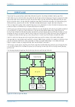
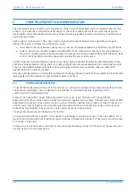
The following diagram shows how the scheme logic interacts with the rest of the IED.
V02011
PSL and FSL
Protection functions
SL
in
pu
ts
SL
o
ut
pu
ts
Opto-inputs
Programmable LEDs
Output relays
Function keys
G
oo
se
in
pu
ts
Control input
module
G
oo
se
o
ut
pu
ts
Ethernet
processing module
Fixed LEDs
C
on
tro
l i
np
ut
s
Energising quantities
Figure 152: Scheme Logic Interfaces
P54A/B/C/E
Chapter 14 - Digital I/O and PSL Configuration
P54xMED-TM-EN-1
301
Содержание P4A
Страница 2: ......
Страница 20: ...Contents P54A B C E xviii P54xMED TM EN 1 ...
Страница 27: ...CHAPTER 1 INTRODUCTION ...
Страница 28: ...Chapter 1 Introduction P54A B C E 2 P54xMED TM EN 1 ...
Страница 38: ...Chapter 1 Introduction P54A B C E 12 P54xMED TM EN 1 ...
Страница 39: ...CHAPTER 2 SAFETY INFORMATION ...
Страница 40: ...Chapter 2 Safety Information P54A B C E 14 P54xMED TM EN 1 ...
Страница 52: ...Chapter 2 Safety Information P54A B C E 26 P54xMED TM EN 1 ...
Страница 53: ...CHAPTER 3 HARDWARE DESIGN ...
Страница 54: ...Chapter 3 Hardware Design P54A B C E 28 P54xMED TM EN 1 ...
Страница 86: ...Chapter 3 Hardware Design P54A B C E 60 P54xMED TM EN 1 ...
Страница 87: ...CHAPTER 4 SOFTWARE DESIGN ...
Страница 88: ...Chapter 4 Software Design P54A B C E 62 P54xMED TM EN 1 ...
Страница 99: ...CHAPTER 5 CONFIGURATION ...
Страница 100: ...Chapter 5 Configuration P54A B C E 74 P54xMED TM EN 1 ...
Страница 120: ...Chapter 5 Configuration P54A B C E 94 P54xMED TM EN 1 ...
Страница 121: ...CHAPTER 6 CURRENT DIFFERENTIAL PROTECTION ...
Страница 122: ...Chapter 6 Current Differential Protection P54A B C E 96 P54xMED TM EN 1 ...
Страница 149: ...CHAPTER 7 AUTORECLOSE ...
Страница 150: ...Chapter 7 Autoreclose P54A B C E 124 P54xMED TM EN 1 ...
Страница 207: ...CHAPTER 8 CB FAIL PROTECTION ...
Страница 208: ...Chapter 8 CB Fail Protection P54A B C E 182 P54xMED TM EN 1 ...
Страница 219: ...CHAPTER 9 CURRENT PROTECTION FUNCTIONS ...
Страница 220: ...Chapter 9 Current Protection Functions P54A B C E 194 P54xMED TM EN 1 ...
Страница 244: ...Chapter 9 Current Protection Functions P54A B C E 218 P54xMED TM EN 1 ...
Страница 247: ...CHAPTER 10 VOLTAGE PROTECTION FUNCTIONS ...
Страница 248: ...Chapter 10 Voltage Protection Functions P54A B C E 222 P54xMED TM EN 1 ...
Страница 261: ...CHAPTER 11 FREQUENCY PROTECTION FUNCTIONS ...
Страница 262: ...Chapter 11 Frequency Protection Functions P54A B C E 236 P54xMED TM EN 1 ...
Страница 268: ...Chapter 11 Frequency Protection Functions P54A B C E 242 P54xMED TM EN 1 ...
Страница 269: ...CHAPTER 12 MONITORING AND CONTROL ...
Страница 270: ...Chapter 12 Monitoring and Control P54A B C E 244 P54xMED TM EN 1 ...
Страница 300: ...Chapter 12 Monitoring and Control P54A B C E 274 P54xMED TM EN 1 ...
Страница 301: ...CHAPTER 13 SUPERVISION ...
Страница 302: ...Chapter 13 Supervision P54A B C E 276 P54xMED TM EN 1 ...
Страница 312: ...Chapter 13 Supervision P54A B C E 286 P54xMED TM EN 1 ...
Страница 323: ...CHAPTER 14 DIGITAL I O AND PSL CONFIGURATION ...
Страница 324: ...Chapter 14 Digital I O and PSL Configuration P54A B C E 298 P54xMED TM EN 1 ...
Страница 336: ...Chapter 14 Digital I O and PSL Configuration P54A B C E 310 P54xMED TM EN 1 ...
Страница 337: ...CHAPTER 15 FIBRE TELEPROTECTION ...
Страница 338: ...Chapter 15 Fibre Teleprotection P54A B C E 312 P54xMED TM EN 1 ...
Страница 354: ...Chapter 15 Fibre Teleprotection P54A B C E 328 P54xMED TM EN 1 ...
Страница 355: ...CHAPTER 16 ELECTRICAL TELEPROTECTION ...
Страница 356: ...Chapter 16 Electrical Teleprotection P54A B C E 330 P54xMED TM EN 1 ...
Страница 366: ...Chapter 16 Electrical Teleprotection P54A B C E 340 P54xMED TM EN 1 ...
Страница 367: ...CHAPTER 17 COMMUNICATIONS ...
Страница 368: ...Chapter 17 Communications P54A B C E 342 P54xMED TM EN 1 ...
Страница 439: ...CHAPTER 18 CYBER SECURITY ...
Страница 440: ...Chapter 18 Cyber Security P54A B C E 414 P54xMED TM EN 1 ...
Страница 457: ...CHAPTER 19 INSTALLATION ...
Страница 458: ...Chapter 19 Installation P54A B C E 432 P54xMED TM EN 1 ...
Страница 469: ...5 2 CASE DIMENSIONS 60TE E01409 Figure 197 60TE case dimensions P54A B C E Chapter 19 Installation P54xMED TM EN 1 443 ...
Страница 471: ...CHAPTER 20 COMMISSIONING INSTRUCTIONS ...
Страница 472: ...Chapter 20 Commissioning Instructions P54A B C E 446 P54xMED TM EN 1 ...
Страница 513: ...CHAPTER 21 MAINTENANCE AND TROUBLESHOOTING ...
Страница 514: ...Chapter 21 Maintenance and Troubleshooting P54A B C E 488 P54xMED TM EN 1 ...
Страница 530: ...Chapter 21 Maintenance and Troubleshooting P54A B C E 504 P54xMED TM EN 1 ...
Страница 531: ...CHAPTER 22 TECHNICAL SPECIFICATIONS ...
Страница 532: ...Chapter 22 Technical Specifications P54A B C E 506 P54xMED TM EN 1 ...
Страница 558: ...Chapter 22 Technical Specifications P54A B C E 532 P54xMED TM EN 1 ...
Страница 559: ...APPENDIX A ORDERING OPTIONS ...
Страница 560: ...Appendix A Ordering Options P54A B C E P54xMED TM EN 1 ...
Страница 565: ...APPENDIX B SETTINGS AND SIGNALS ...
Страница 566: ...Appendix B Settings and Signals P54A B C E P54xMED TM EN 1 ...
Страница 790: ...Appendix B Settings and Signals P54A B C E B224 P54xMED TM EN 1 ...
Страница 835: ...APPENDIX C WIRING DIAGRAMS ...
Страница 836: ...Appendix C Wiring Diagrams P54A B C E P54xMED TM EN 1 ...
Страница 849: ......