


4
MEASUREMENTS
4.1
MEASURED QUANTITIES
The device measures directly and calculates a number of system quantities, which are updated every second. You
can view these values in the relevant MEASUREMENT columns or with the Measurement Viewer in the settings
application software. Depending on the model, the device may measure and display some or more of the following
quantities:
●
Measured and calculated analogue current and voltage values
●
Power and energy quantities
●
Peak, fixed and rolling demand values
●
Frequency measurements
●
Thermal measurements
●
Teleprotection channel measurements
4.2
MEASUREMENT SETUP
You can define the way measurements are set up and displayed using the MEASURE'T SETUP column and the
measurements are shown in the relevant MEASUREMENTS tables.
4.3
FAULT LOCATOR
Some models provide fault location functionality. It is possible to identify the fault location by measuring the fault
voltage and current magnitude and phases and presenting this information to a Fault Locator function. The fault
locator is triggered whenever a fault record is generated, and the subsequent fault location data is included as
part of the fault record. This information is also displayed in the Fault Location cell in the VIEW RECORDS column.
This cell will display the fault location in metres, miles ohms or percentage, depending on the chosen units in the
Fault Location cell of the MEASURE'T SETUP column.
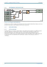
The Fault Locator uses pre-fault and post-fault analogue input signals to calculate the fault location. The result is
included it in the fault record. The pre-fault and post-fault voltages are also presented in the fault record.
When applied to parallel circuits, mutual flux coupling can alter the impedance seen by the fault locator. The
coupling contains positive, negative and zero sequence components. In practise the positive and negative
sequence coupling is insignificant. The effect on the fault locator of the zero sequence mutual coupling can be
eliminated using the mutual compensation feature provided.
Note:
Multi-ended line differential relays support fault location from the local terminal only. For this reason, the LINE PARAMETERS
setting shall be set based on the parameters of the local to the nearest junction at each relay.
4.4
OPTO-INPUT TIME STAMPING
Each opto-input sample is time stamped within a tolerance of +/- 1 ms with respect to the Real Time Clock. These
time stamps are used for the opto event logs and for the disturbance recording. The device needs to be
synchronised accurately to an external clock source such as an IRIG-B signal or a master clock signal provided in
the relevant data protocol.
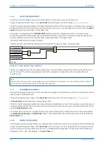
For both the filtered and unfiltered opto-inputs, the time stamp of an opto-input change event is the sampling time
at which the change of state occurred. If multiple opto-inputs change state at the same sampling interval, these
state changes are reported as a single event.
P54A/B/C/E
Chapter 12 - Monitoring and Control
P54xMED-TM-EN-1
251
Содержание P4A
Страница 2: ......
Страница 20: ...Contents P54A B C E xviii P54xMED TM EN 1 ...
Страница 27: ...CHAPTER 1 INTRODUCTION ...
Страница 28: ...Chapter 1 Introduction P54A B C E 2 P54xMED TM EN 1 ...
Страница 38: ...Chapter 1 Introduction P54A B C E 12 P54xMED TM EN 1 ...
Страница 39: ...CHAPTER 2 SAFETY INFORMATION ...
Страница 40: ...Chapter 2 Safety Information P54A B C E 14 P54xMED TM EN 1 ...
Страница 52: ...Chapter 2 Safety Information P54A B C E 26 P54xMED TM EN 1 ...
Страница 53: ...CHAPTER 3 HARDWARE DESIGN ...
Страница 54: ...Chapter 3 Hardware Design P54A B C E 28 P54xMED TM EN 1 ...
Страница 86: ...Chapter 3 Hardware Design P54A B C E 60 P54xMED TM EN 1 ...
Страница 87: ...CHAPTER 4 SOFTWARE DESIGN ...
Страница 88: ...Chapter 4 Software Design P54A B C E 62 P54xMED TM EN 1 ...
Страница 99: ...CHAPTER 5 CONFIGURATION ...
Страница 100: ...Chapter 5 Configuration P54A B C E 74 P54xMED TM EN 1 ...
Страница 120: ...Chapter 5 Configuration P54A B C E 94 P54xMED TM EN 1 ...
Страница 121: ...CHAPTER 6 CURRENT DIFFERENTIAL PROTECTION ...
Страница 122: ...Chapter 6 Current Differential Protection P54A B C E 96 P54xMED TM EN 1 ...
Страница 149: ...CHAPTER 7 AUTORECLOSE ...
Страница 150: ...Chapter 7 Autoreclose P54A B C E 124 P54xMED TM EN 1 ...
Страница 207: ...CHAPTER 8 CB FAIL PROTECTION ...
Страница 208: ...Chapter 8 CB Fail Protection P54A B C E 182 P54xMED TM EN 1 ...
Страница 219: ...CHAPTER 9 CURRENT PROTECTION FUNCTIONS ...
Страница 220: ...Chapter 9 Current Protection Functions P54A B C E 194 P54xMED TM EN 1 ...
Страница 244: ...Chapter 9 Current Protection Functions P54A B C E 218 P54xMED TM EN 1 ...
Страница 247: ...CHAPTER 10 VOLTAGE PROTECTION FUNCTIONS ...
Страница 248: ...Chapter 10 Voltage Protection Functions P54A B C E 222 P54xMED TM EN 1 ...
Страница 261: ...CHAPTER 11 FREQUENCY PROTECTION FUNCTIONS ...
Страница 262: ...Chapter 11 Frequency Protection Functions P54A B C E 236 P54xMED TM EN 1 ...
Страница 268: ...Chapter 11 Frequency Protection Functions P54A B C E 242 P54xMED TM EN 1 ...
Страница 269: ...CHAPTER 12 MONITORING AND CONTROL ...
Страница 270: ...Chapter 12 Monitoring and Control P54A B C E 244 P54xMED TM EN 1 ...
Страница 300: ...Chapter 12 Monitoring and Control P54A B C E 274 P54xMED TM EN 1 ...
Страница 301: ...CHAPTER 13 SUPERVISION ...
Страница 302: ...Chapter 13 Supervision P54A B C E 276 P54xMED TM EN 1 ...
Страница 312: ...Chapter 13 Supervision P54A B C E 286 P54xMED TM EN 1 ...
Страница 323: ...CHAPTER 14 DIGITAL I O AND PSL CONFIGURATION ...
Страница 324: ...Chapter 14 Digital I O and PSL Configuration P54A B C E 298 P54xMED TM EN 1 ...
Страница 336: ...Chapter 14 Digital I O and PSL Configuration P54A B C E 310 P54xMED TM EN 1 ...
Страница 337: ...CHAPTER 15 FIBRE TELEPROTECTION ...
Страница 338: ...Chapter 15 Fibre Teleprotection P54A B C E 312 P54xMED TM EN 1 ...
Страница 354: ...Chapter 15 Fibre Teleprotection P54A B C E 328 P54xMED TM EN 1 ...
Страница 355: ...CHAPTER 16 ELECTRICAL TELEPROTECTION ...
Страница 356: ...Chapter 16 Electrical Teleprotection P54A B C E 330 P54xMED TM EN 1 ...
Страница 366: ...Chapter 16 Electrical Teleprotection P54A B C E 340 P54xMED TM EN 1 ...
Страница 367: ...CHAPTER 17 COMMUNICATIONS ...
Страница 368: ...Chapter 17 Communications P54A B C E 342 P54xMED TM EN 1 ...
Страница 439: ...CHAPTER 18 CYBER SECURITY ...
Страница 440: ...Chapter 18 Cyber Security P54A B C E 414 P54xMED TM EN 1 ...
Страница 457: ...CHAPTER 19 INSTALLATION ...
Страница 458: ...Chapter 19 Installation P54A B C E 432 P54xMED TM EN 1 ...
Страница 469: ...5 2 CASE DIMENSIONS 60TE E01409 Figure 197 60TE case dimensions P54A B C E Chapter 19 Installation P54xMED TM EN 1 443 ...
Страница 471: ...CHAPTER 20 COMMISSIONING INSTRUCTIONS ...
Страница 472: ...Chapter 20 Commissioning Instructions P54A B C E 446 P54xMED TM EN 1 ...
Страница 513: ...CHAPTER 21 MAINTENANCE AND TROUBLESHOOTING ...
Страница 514: ...Chapter 21 Maintenance and Troubleshooting P54A B C E 488 P54xMED TM EN 1 ...
Страница 530: ...Chapter 21 Maintenance and Troubleshooting P54A B C E 504 P54xMED TM EN 1 ...
Страница 531: ...CHAPTER 22 TECHNICAL SPECIFICATIONS ...
Страница 532: ...Chapter 22 Technical Specifications P54A B C E 506 P54xMED TM EN 1 ...
Страница 558: ...Chapter 22 Technical Specifications P54A B C E 532 P54xMED TM EN 1 ...
Страница 559: ...APPENDIX A ORDERING OPTIONS ...
Страница 560: ...Appendix A Ordering Options P54A B C E P54xMED TM EN 1 ...
Страница 565: ...APPENDIX B SETTINGS AND SIGNALS ...
Страница 566: ...Appendix B Settings and Signals P54A B C E P54xMED TM EN 1 ...
Страница 790: ...Appendix B Settings and Signals P54A B C E B224 P54xMED TM EN 1 ...
Страница 835: ...APPENDIX C WIRING DIAGRAMS ...
Страница 836: ...Appendix C Wiring Diagrams P54A B C E P54xMED TM EN 1 ...
Страница 849: ......