


Appendix B - Settings and Signals
P54A/B/C/E
B190
P54xMED-TM-EN-1
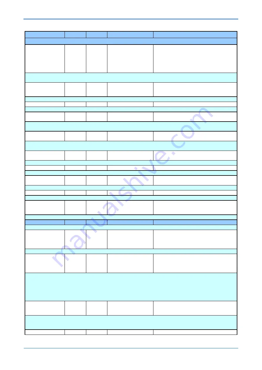
MENU TEXT
COL
ROW
DEFAULT SETTING
AVAILABLE OPTIONS
DESCRIPTION
CB1 Ext Prot Rst
45
07
Prot Reset & I<
I< Only
CB Open & I<
Prot Reset & I<
Prot Reset or I<
Rst or CBOp & I<
[Indexed String]
Setting which determines the elements that will reset the circuit breaker fail time for external protection function initiated circuit breaker fail
conditions.
ExtTrip Only Ini
45
09
Disabled
Disabled
Enabled
[Indexed String]
When Enabled, CB Fail timers will only be initiated by External Trip inputs.
UNDER CURRENT
45
0A
Pole Dead Sub Heading
CB1 I< Set
45
0B
0.05
From 0.02*I1 to 3.2*I1 in steps of 0.01*I1
[Courier Number (current)]
Setting that determines the circuit breaker fail timer reset current for overcurrent based protection circuit breaker fail initiation. This setting
is also used in the pole dead logic to determine the status of the pole (dead or live).
CB2 I< Set
45
0C
0.05
From 0.02*I1 to 3.2*I1 in steps of 0.01*I1
[Courier Number (current)]
Setting that determines the circuit breaker fail timer reset current for overcurrent based protection circuit breaker fail initiation. This setting
is also used in the pole dead logic to determine the status of the pole (dead or live).
ISEF< Current
45
0D
0.02
From 0.001*I3 to 0.8*I3 in steps of 0.0005*I3
[Courier Number (current)]
Setting that determines the circuit breaker fail timer reset current for Sensitive earth fault (SEF) protection circuit breaker fail initiation.
POLEDEAD VOLTAGE
45
0E
Pole Dead Sub Heading
V<
45
10
38.1
From 10*V1 to 40*V1 in steps of 0.1*V1
[Courier Number (voltage)]
Under voltage level detector for pole dead detection
BREAKER FAIL CB2
45
21
Breaker fail Sub Heading
CB2 Fail1 Status
45
22
Enabled
Disabled
Enabled
[Indexed String]
Setting to enable or disable the first stage of the circuit breaker function.
GROUP 1: SUPERVISION
46
00
This column contains settings for Voltage and Current Supervision
VTS Mode
46
01
Me MCB
Me MCB
Measured Only
MCB Only
[Indexed String]
Setting that determines the method to be used to declare VT failure.
VTS Status
46
02
Blocking
Disabled
Blocking
Indication
[Indexed String]
This setting determines whether the following operations will occur upon detection of VTS.
• VTS set to provide alarm indication only.
• Optional blocking of voltage dependent protection elements.
• Optional conversion of directional overcurrent elements to non-directional protection
(available when set to blocking mode only). These settings are found in the function links cell of the relevant protection element columns in
the menu.
VTS Reset Mode
46
03
Auto
Manual
Auto
[Indexed String]
The VTS block will be latched after a user settable time delay ‘VTS Time Delay’. Once the signal has latched then two methods of resetting
are available. The first is manually via the front panel interface (or remote communications) and secondly, when in ‘Auto’ mode, provided the
VTS condition has been removed and the 3 phase voltages have been restored above the phase level detector settings for more than 240 ms.
VTS Time Delay
46
04
5
From 1 to 10 in steps of 0.1
Содержание P4A
Страница 2: ......
Страница 20: ...Contents P54A B C E xviii P54xMED TM EN 1 ...
Страница 27: ...CHAPTER 1 INTRODUCTION ...
Страница 28: ...Chapter 1 Introduction P54A B C E 2 P54xMED TM EN 1 ...
Страница 38: ...Chapter 1 Introduction P54A B C E 12 P54xMED TM EN 1 ...
Страница 39: ...CHAPTER 2 SAFETY INFORMATION ...
Страница 40: ...Chapter 2 Safety Information P54A B C E 14 P54xMED TM EN 1 ...
Страница 52: ...Chapter 2 Safety Information P54A B C E 26 P54xMED TM EN 1 ...
Страница 53: ...CHAPTER 3 HARDWARE DESIGN ...
Страница 54: ...Chapter 3 Hardware Design P54A B C E 28 P54xMED TM EN 1 ...
Страница 86: ...Chapter 3 Hardware Design P54A B C E 60 P54xMED TM EN 1 ...
Страница 87: ...CHAPTER 4 SOFTWARE DESIGN ...
Страница 88: ...Chapter 4 Software Design P54A B C E 62 P54xMED TM EN 1 ...
Страница 99: ...CHAPTER 5 CONFIGURATION ...
Страница 100: ...Chapter 5 Configuration P54A B C E 74 P54xMED TM EN 1 ...
Страница 120: ...Chapter 5 Configuration P54A B C E 94 P54xMED TM EN 1 ...
Страница 121: ...CHAPTER 6 CURRENT DIFFERENTIAL PROTECTION ...
Страница 122: ...Chapter 6 Current Differential Protection P54A B C E 96 P54xMED TM EN 1 ...
Страница 149: ...CHAPTER 7 AUTORECLOSE ...
Страница 150: ...Chapter 7 Autoreclose P54A B C E 124 P54xMED TM EN 1 ...
Страница 207: ...CHAPTER 8 CB FAIL PROTECTION ...
Страница 208: ...Chapter 8 CB Fail Protection P54A B C E 182 P54xMED TM EN 1 ...
Страница 219: ...CHAPTER 9 CURRENT PROTECTION FUNCTIONS ...
Страница 220: ...Chapter 9 Current Protection Functions P54A B C E 194 P54xMED TM EN 1 ...
Страница 244: ...Chapter 9 Current Protection Functions P54A B C E 218 P54xMED TM EN 1 ...
Страница 247: ...CHAPTER 10 VOLTAGE PROTECTION FUNCTIONS ...
Страница 248: ...Chapter 10 Voltage Protection Functions P54A B C E 222 P54xMED TM EN 1 ...
Страница 261: ...CHAPTER 11 FREQUENCY PROTECTION FUNCTIONS ...
Страница 262: ...Chapter 11 Frequency Protection Functions P54A B C E 236 P54xMED TM EN 1 ...
Страница 268: ...Chapter 11 Frequency Protection Functions P54A B C E 242 P54xMED TM EN 1 ...
Страница 269: ...CHAPTER 12 MONITORING AND CONTROL ...
Страница 270: ...Chapter 12 Monitoring and Control P54A B C E 244 P54xMED TM EN 1 ...
Страница 300: ...Chapter 12 Monitoring and Control P54A B C E 274 P54xMED TM EN 1 ...
Страница 301: ...CHAPTER 13 SUPERVISION ...
Страница 302: ...Chapter 13 Supervision P54A B C E 276 P54xMED TM EN 1 ...
Страница 312: ...Chapter 13 Supervision P54A B C E 286 P54xMED TM EN 1 ...
Страница 323: ...CHAPTER 14 DIGITAL I O AND PSL CONFIGURATION ...
Страница 324: ...Chapter 14 Digital I O and PSL Configuration P54A B C E 298 P54xMED TM EN 1 ...
Страница 336: ...Chapter 14 Digital I O and PSL Configuration P54A B C E 310 P54xMED TM EN 1 ...
Страница 337: ...CHAPTER 15 FIBRE TELEPROTECTION ...
Страница 338: ...Chapter 15 Fibre Teleprotection P54A B C E 312 P54xMED TM EN 1 ...
Страница 354: ...Chapter 15 Fibre Teleprotection P54A B C E 328 P54xMED TM EN 1 ...
Страница 355: ...CHAPTER 16 ELECTRICAL TELEPROTECTION ...
Страница 356: ...Chapter 16 Electrical Teleprotection P54A B C E 330 P54xMED TM EN 1 ...
Страница 366: ...Chapter 16 Electrical Teleprotection P54A B C E 340 P54xMED TM EN 1 ...
Страница 367: ...CHAPTER 17 COMMUNICATIONS ...
Страница 368: ...Chapter 17 Communications P54A B C E 342 P54xMED TM EN 1 ...
Страница 439: ...CHAPTER 18 CYBER SECURITY ...
Страница 440: ...Chapter 18 Cyber Security P54A B C E 414 P54xMED TM EN 1 ...
Страница 457: ...CHAPTER 19 INSTALLATION ...
Страница 458: ...Chapter 19 Installation P54A B C E 432 P54xMED TM EN 1 ...
Страница 469: ...5 2 CASE DIMENSIONS 60TE E01409 Figure 197 60TE case dimensions P54A B C E Chapter 19 Installation P54xMED TM EN 1 443 ...
Страница 471: ...CHAPTER 20 COMMISSIONING INSTRUCTIONS ...
Страница 472: ...Chapter 20 Commissioning Instructions P54A B C E 446 P54xMED TM EN 1 ...
Страница 513: ...CHAPTER 21 MAINTENANCE AND TROUBLESHOOTING ...
Страница 514: ...Chapter 21 Maintenance and Troubleshooting P54A B C E 488 P54xMED TM EN 1 ...
Страница 530: ...Chapter 21 Maintenance and Troubleshooting P54A B C E 504 P54xMED TM EN 1 ...
Страница 531: ...CHAPTER 22 TECHNICAL SPECIFICATIONS ...
Страница 532: ...Chapter 22 Technical Specifications P54A B C E 506 P54xMED TM EN 1 ...
Страница 558: ...Chapter 22 Technical Specifications P54A B C E 532 P54xMED TM EN 1 ...
Страница 559: ...APPENDIX A ORDERING OPTIONS ...
Страница 560: ...Appendix A Ordering Options P54A B C E P54xMED TM EN 1 ...
Страница 565: ...APPENDIX B SETTINGS AND SIGNALS ...
Страница 566: ...Appendix B Settings and Signals P54A B C E P54xMED TM EN 1 ...
Страница 790: ...Appendix B Settings and Signals P54A B C E B224 P54xMED TM EN 1 ...
Страница 835: ...APPENDIX C WIRING DIAGRAMS ...
Страница 836: ...Appendix C Wiring Diagrams P54A B C E P54xMED TM EN 1 ...
Страница 849: ......