


Appendix B - Settings and Signals
P54A/B/C/E
B160
P54xMED-TM-EN-1
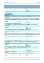
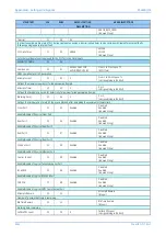
MENU TEXT
COL
ROW
DEFAULT SETTING
AVAILABLE OPTIONS
DESCRIPTION
Setting that defines the operative mode of the received InterMiCOM_4 signal.
When ‘Direct’ tripping is chosen, for security reasons 2 consecutive valid messages have to be received before a change in the signal status
will be acknowledged. That will impose an additional 1-2 ms delay comparing to ‘Permissive’ mode.
Set ‘Direct’ in Direct Transfer Tripping (Intertripping) applications.
Set ‘Permissive’ to accommodate any Permissive or Blocking scheme.
IM4 FallBackMode
20
8C
Default
Default
Latched
[Indexed String]
Setting that defines the status of IM4 signal in case of heavy noise and message synchronization being lost.
If set to Latching the last valid IM4 status will be maintained until the new valid message is received.
If set to Default, the IM4 status, pre-defined by the user in IM4 Default Value cell will be set. A new valid message will replace IM4 Default
Value, once the channel recovers.
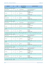
IM4 DefaultValue
20
8D
0
0 or 1
[Unsigned Integer(16 bit)]
Setting that defines the IM4 fallback status.
IM5 Cmd Type
20
8E
Permissive
Direct
Permissive
[Indexed String]
Setting that defines the operative mode of the received InterMiCOM_5 signal.
When ‘Direct’ tripping is chosen, for security reasons 2 consecutive valid messages have to be received before a change in the signal status
will be acknowledged. That will impose an additional 1-2 ms delay comparing to ‘Permissive’ mode.
Set ‘Direct’ in Direct Transfer Tripping (Intertripping) applications.
Set ‘Permissive’ to accommodate any Permissive or Blocking scheme.
IM5 FallBackMode
20
8F
Default
Default
Latched
[Indexed String]
Setting that defines the status of IM5 signal in case of heavy noise and message synchronization being lost.
If set to Latching the last valid IM5 status will be maintained until the new valid message is received.
If set to Default, the IM5 status, pre-defined by the user in IM5 Default Value cell will be set. A new valid message will replace IM5 Default
Value, once the channel recovers.
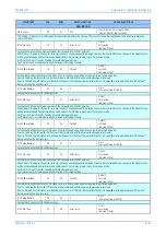
IM5 DefaultValue
20
90
0
0 or 1
[Unsigned Integer(16 bit)]
Setting that defines the IM5 fallback status.
IM6 Cmd Type
20
91
Permissive
Direct
Permissive
[Indexed String]
Setting that defines the operative mode of the received InterMiCOM_6 signal.
When ‘Direct’ tripping is chosen, for security reasons 2 consecutive valid messages have to be received before a change in the signal status
will be acknowledged. That will impose an additional 1-2 ms delay comparing to ‘Permissive’ mode.
Set ‘Direct’ in Direct Transfer Tripping (Intertripping) applications.
Set ‘Permissive’ to accommodate any Permissive or Blocking scheme.
IM6 FallBackMode
20
92
Default
Default
Latched
[Indexed String]
Setting that defines the status of IM6 signal in case of heavy noise and message synchronization being lost.
If set to Latching the last valid IM6 status will be maintained until the new valid message is received.
If set to Default, the IM6 status, pre-defined by the user in IM6 Default Value cell will be set. A new valid message will replace IM6 Default
Value, once the channel recovers.
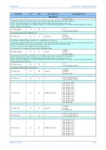
IM6 DefaultValue
20
93
0
0 or 1
[Unsigned Integer(16 bit)]
Setting that defines the IM6 fallback status.
IM7 Cmd Type
20
94
Permissive
Direct
Permissive
[Indexed String]
Setting that defines the operative mode of the received InterMiCOM_7 signal.
When ‘Direct’ tripping is chosen, for security reasons 2 consecutive valid messages have to be received before a change in the signal status
will be acknowledged. That will impose an additional 1-2 ms delay comparing to ‘Permissive’ mode.
Set ‘Direct’ in Direct Transfer Tripping (Intertripping) applications.
Set ‘Permissive’ to accommodate any Permissive or Blocking scheme.
IM7 FallBackMode
20
95
Default
Default
Latched
Содержание P4A
Страница 2: ......
Страница 20: ...Contents P54A B C E xviii P54xMED TM EN 1 ...
Страница 27: ...CHAPTER 1 INTRODUCTION ...
Страница 28: ...Chapter 1 Introduction P54A B C E 2 P54xMED TM EN 1 ...
Страница 38: ...Chapter 1 Introduction P54A B C E 12 P54xMED TM EN 1 ...
Страница 39: ...CHAPTER 2 SAFETY INFORMATION ...
Страница 40: ...Chapter 2 Safety Information P54A B C E 14 P54xMED TM EN 1 ...
Страница 52: ...Chapter 2 Safety Information P54A B C E 26 P54xMED TM EN 1 ...
Страница 53: ...CHAPTER 3 HARDWARE DESIGN ...
Страница 54: ...Chapter 3 Hardware Design P54A B C E 28 P54xMED TM EN 1 ...
Страница 86: ...Chapter 3 Hardware Design P54A B C E 60 P54xMED TM EN 1 ...
Страница 87: ...CHAPTER 4 SOFTWARE DESIGN ...
Страница 88: ...Chapter 4 Software Design P54A B C E 62 P54xMED TM EN 1 ...
Страница 99: ...CHAPTER 5 CONFIGURATION ...
Страница 100: ...Chapter 5 Configuration P54A B C E 74 P54xMED TM EN 1 ...
Страница 120: ...Chapter 5 Configuration P54A B C E 94 P54xMED TM EN 1 ...
Страница 121: ...CHAPTER 6 CURRENT DIFFERENTIAL PROTECTION ...
Страница 122: ...Chapter 6 Current Differential Protection P54A B C E 96 P54xMED TM EN 1 ...
Страница 149: ...CHAPTER 7 AUTORECLOSE ...
Страница 150: ...Chapter 7 Autoreclose P54A B C E 124 P54xMED TM EN 1 ...
Страница 207: ...CHAPTER 8 CB FAIL PROTECTION ...
Страница 208: ...Chapter 8 CB Fail Protection P54A B C E 182 P54xMED TM EN 1 ...
Страница 219: ...CHAPTER 9 CURRENT PROTECTION FUNCTIONS ...
Страница 220: ...Chapter 9 Current Protection Functions P54A B C E 194 P54xMED TM EN 1 ...
Страница 244: ...Chapter 9 Current Protection Functions P54A B C E 218 P54xMED TM EN 1 ...
Страница 247: ...CHAPTER 10 VOLTAGE PROTECTION FUNCTIONS ...
Страница 248: ...Chapter 10 Voltage Protection Functions P54A B C E 222 P54xMED TM EN 1 ...
Страница 261: ...CHAPTER 11 FREQUENCY PROTECTION FUNCTIONS ...
Страница 262: ...Chapter 11 Frequency Protection Functions P54A B C E 236 P54xMED TM EN 1 ...
Страница 268: ...Chapter 11 Frequency Protection Functions P54A B C E 242 P54xMED TM EN 1 ...
Страница 269: ...CHAPTER 12 MONITORING AND CONTROL ...
Страница 270: ...Chapter 12 Monitoring and Control P54A B C E 244 P54xMED TM EN 1 ...
Страница 300: ...Chapter 12 Monitoring and Control P54A B C E 274 P54xMED TM EN 1 ...
Страница 301: ...CHAPTER 13 SUPERVISION ...
Страница 302: ...Chapter 13 Supervision P54A B C E 276 P54xMED TM EN 1 ...
Страница 312: ...Chapter 13 Supervision P54A B C E 286 P54xMED TM EN 1 ...
Страница 323: ...CHAPTER 14 DIGITAL I O AND PSL CONFIGURATION ...
Страница 324: ...Chapter 14 Digital I O and PSL Configuration P54A B C E 298 P54xMED TM EN 1 ...
Страница 336: ...Chapter 14 Digital I O and PSL Configuration P54A B C E 310 P54xMED TM EN 1 ...
Страница 337: ...CHAPTER 15 FIBRE TELEPROTECTION ...
Страница 338: ...Chapter 15 Fibre Teleprotection P54A B C E 312 P54xMED TM EN 1 ...
Страница 354: ...Chapter 15 Fibre Teleprotection P54A B C E 328 P54xMED TM EN 1 ...
Страница 355: ...CHAPTER 16 ELECTRICAL TELEPROTECTION ...
Страница 356: ...Chapter 16 Electrical Teleprotection P54A B C E 330 P54xMED TM EN 1 ...
Страница 366: ...Chapter 16 Electrical Teleprotection P54A B C E 340 P54xMED TM EN 1 ...
Страница 367: ...CHAPTER 17 COMMUNICATIONS ...
Страница 368: ...Chapter 17 Communications P54A B C E 342 P54xMED TM EN 1 ...
Страница 439: ...CHAPTER 18 CYBER SECURITY ...
Страница 440: ...Chapter 18 Cyber Security P54A B C E 414 P54xMED TM EN 1 ...
Страница 457: ...CHAPTER 19 INSTALLATION ...
Страница 458: ...Chapter 19 Installation P54A B C E 432 P54xMED TM EN 1 ...
Страница 469: ...5 2 CASE DIMENSIONS 60TE E01409 Figure 197 60TE case dimensions P54A B C E Chapter 19 Installation P54xMED TM EN 1 443 ...
Страница 471: ...CHAPTER 20 COMMISSIONING INSTRUCTIONS ...
Страница 472: ...Chapter 20 Commissioning Instructions P54A B C E 446 P54xMED TM EN 1 ...
Страница 513: ...CHAPTER 21 MAINTENANCE AND TROUBLESHOOTING ...
Страница 514: ...Chapter 21 Maintenance and Troubleshooting P54A B C E 488 P54xMED TM EN 1 ...
Страница 530: ...Chapter 21 Maintenance and Troubleshooting P54A B C E 504 P54xMED TM EN 1 ...
Страница 531: ...CHAPTER 22 TECHNICAL SPECIFICATIONS ...
Страница 532: ...Chapter 22 Technical Specifications P54A B C E 506 P54xMED TM EN 1 ...
Страница 558: ...Chapter 22 Technical Specifications P54A B C E 532 P54xMED TM EN 1 ...
Страница 559: ...APPENDIX A ORDERING OPTIONS ...
Страница 560: ...Appendix A Ordering Options P54A B C E P54xMED TM EN 1 ...
Страница 565: ...APPENDIX B SETTINGS AND SIGNALS ...
Страница 566: ...Appendix B Settings and Signals P54A B C E P54xMED TM EN 1 ...
Страница 790: ...Appendix B Settings and Signals P54A B C E B224 P54xMED TM EN 1 ...
Страница 835: ...APPENDIX C WIRING DIAGRAMS ...
Страница 836: ...Appendix C Wiring Diagrams P54A B C E P54xMED TM EN 1 ...
Страница 849: ......