


Appendix B - Settings and Signals
P54A/B/C/E
B158
P54xMED-TM-EN-1
MENU TEXT
COL
ROW
DEFAULT SETTING
AVAILABLE OPTIONS
DESCRIPTION
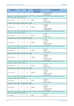
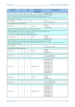
Comm Fail Timer
20
76
10
From 0.1 to 600 in steps of 0.1s
[Courier Number (time-seconds)]
Time delay after which the ‘Channel Fail Alarm’ will be issued providing that no messages were received during the ‘Channel Timeout’ period
or the ‘Alarm Level’ is exceeded.
Comm Fail Mode
20
77
Ch 1 or 2 Fail
Ch 1 Failure
Ch 2 Failure
Ch 1 or 2 Fail
Ch 1 and 2 Fail
[Indexed String]
Fail mode setting that triggers the ‘Channel Fail Alarm’, providing that the Dual Redundancy or 3 ended scheme is set.
Normally the alarm would be raised for any loss of an operational channel (logical OR combination). However, when IED's in a 3 ended
scheme are deliberately operated in Chain topology AND logic may be used, for indication when the scheme becomes finally inoperative,
with no self-healing (signal rerouting) mode possible.
Char Mod Time
20
78
0.5
From 0 to 30 in steps of 0.0001
[Courier Number (time-seconds)]
Time delay during which the setting characteristic k1 is increased to 200% after the difference between 2 successive calculated propagation
delay time exceed the time delay setting Comm Delay Tol. This should be set to greater than the maximum switching delay expected.
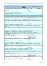
Char Mod Reset
20
79
Disabled
Disabled
Enabled
[Indexed String]
Setting to enable Char Mod Ex Time.
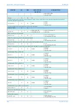
Char Mod RstTime
20
7A
0.5
From 0 to 30s in steps of 0.0001s
[Courier Number (time-seconds)]
If the Char Mod Time has started then the Char Mod Ex Timer runs. If at the end of this timer and until Char Mod Time has expired, the bias
current is above 5% In, and differential current is below 10% of bias current on all phases, then the Char Mod Time will reset and the
characteristic will return to normal. If these conditions are not met, then the characteristic remains increased for the duration of the Char
Mod Time. Char Mod Ex Timer should be set greater than the minimum switching delay expected, and less than Char Mod Time.
Comm Delay Tol
20
7B
0.00035
From 0.00025s to 0.001s in steps of 0.00005s
[Courier Number (time-seconds)]
If the difference between 2 successive calculated propagation times exceed this time delay setting, then the IED will initiate a change in IED
setting for a short time period (“Char Mod Time” setting) and will raise a Comm Delay Alarm.
Channel Timeout
20
7C
0.1
From 0.1s to 10 in steps of 0.1s
[Courier Number (time-seconds)]
A rolling time window beyond which any of the 8 IM signals that are set to ‘Default’ will be replaced by the corresponding ‘IM_X Default
Value’ setting, providing that no valid message is received on that channel in the meantime. The ‘Chnl Fail Alarm’ timer will be also initiated.
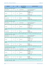
If only one channel is used, each out of 16 IM signals available that is set to ‘Default’ will convert to corresponding ‘IM_X Default Value’
If a Dual redundant or 3 ended scheme is selected, each out of 8 IM signals available that is set to ‘Default’ will convert to corresponding
‘IM_X Default Value’, but only for the affected channel.
Prop Delay Stats
20
7D
Enabled
Disabled
Enabled
[Indexed String]
To enable (activate) or disable (turn off) the alarms of Maximum propagation delay time
MaxCh1 PropDelay
20
7E
0.015
From 0.001s to 0.05 in steps of 0.001
[Courier Number (time-seconds)]
When the protection communications are enabled, the overall propagation delay divided by 2 is calculated and the maximum value is
determined and displayed in Measurements 4 column. This value is displayed and compared against this setting. If the setting is exceeded,
an alarm MaxCh1 PropDelay (DDB 1386) is raised.
MaxCh2 PropDelay
20
7F
0.015
From 0.001 to 0.05 in steps of 0.001
[Courier Number (time-seconds)]
When the protection communications are enabled, the overall propagation delay divided by 2 is calculated and the maximum value is
determined and displayed in Measurements 4 column. This value is displayed and compared against this setting. If the setting is exceeded,
an alarm MaxCh2 PropDelay (DDB 1387) is raised.
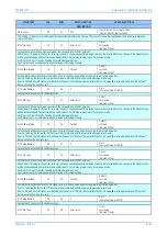
Re-Configuration
20
80
Disabled
A
B
C
D
E
F
[Indexed String]
This setting is to remove or restore one relay from the scheme.
The setting is invisible when 2 Terminal Scheme Setup is selected.
Содержание P4A
Страница 2: ......
Страница 20: ...Contents P54A B C E xviii P54xMED TM EN 1 ...
Страница 27: ...CHAPTER 1 INTRODUCTION ...
Страница 28: ...Chapter 1 Introduction P54A B C E 2 P54xMED TM EN 1 ...
Страница 38: ...Chapter 1 Introduction P54A B C E 12 P54xMED TM EN 1 ...
Страница 39: ...CHAPTER 2 SAFETY INFORMATION ...
Страница 40: ...Chapter 2 Safety Information P54A B C E 14 P54xMED TM EN 1 ...
Страница 52: ...Chapter 2 Safety Information P54A B C E 26 P54xMED TM EN 1 ...
Страница 53: ...CHAPTER 3 HARDWARE DESIGN ...
Страница 54: ...Chapter 3 Hardware Design P54A B C E 28 P54xMED TM EN 1 ...
Страница 86: ...Chapter 3 Hardware Design P54A B C E 60 P54xMED TM EN 1 ...
Страница 87: ...CHAPTER 4 SOFTWARE DESIGN ...
Страница 88: ...Chapter 4 Software Design P54A B C E 62 P54xMED TM EN 1 ...
Страница 99: ...CHAPTER 5 CONFIGURATION ...
Страница 100: ...Chapter 5 Configuration P54A B C E 74 P54xMED TM EN 1 ...
Страница 120: ...Chapter 5 Configuration P54A B C E 94 P54xMED TM EN 1 ...
Страница 121: ...CHAPTER 6 CURRENT DIFFERENTIAL PROTECTION ...
Страница 122: ...Chapter 6 Current Differential Protection P54A B C E 96 P54xMED TM EN 1 ...
Страница 149: ...CHAPTER 7 AUTORECLOSE ...
Страница 150: ...Chapter 7 Autoreclose P54A B C E 124 P54xMED TM EN 1 ...
Страница 207: ...CHAPTER 8 CB FAIL PROTECTION ...
Страница 208: ...Chapter 8 CB Fail Protection P54A B C E 182 P54xMED TM EN 1 ...
Страница 219: ...CHAPTER 9 CURRENT PROTECTION FUNCTIONS ...
Страница 220: ...Chapter 9 Current Protection Functions P54A B C E 194 P54xMED TM EN 1 ...
Страница 244: ...Chapter 9 Current Protection Functions P54A B C E 218 P54xMED TM EN 1 ...
Страница 247: ...CHAPTER 10 VOLTAGE PROTECTION FUNCTIONS ...
Страница 248: ...Chapter 10 Voltage Protection Functions P54A B C E 222 P54xMED TM EN 1 ...
Страница 261: ...CHAPTER 11 FREQUENCY PROTECTION FUNCTIONS ...
Страница 262: ...Chapter 11 Frequency Protection Functions P54A B C E 236 P54xMED TM EN 1 ...
Страница 268: ...Chapter 11 Frequency Protection Functions P54A B C E 242 P54xMED TM EN 1 ...
Страница 269: ...CHAPTER 12 MONITORING AND CONTROL ...
Страница 270: ...Chapter 12 Monitoring and Control P54A B C E 244 P54xMED TM EN 1 ...
Страница 300: ...Chapter 12 Monitoring and Control P54A B C E 274 P54xMED TM EN 1 ...
Страница 301: ...CHAPTER 13 SUPERVISION ...
Страница 302: ...Chapter 13 Supervision P54A B C E 276 P54xMED TM EN 1 ...
Страница 312: ...Chapter 13 Supervision P54A B C E 286 P54xMED TM EN 1 ...
Страница 323: ...CHAPTER 14 DIGITAL I O AND PSL CONFIGURATION ...
Страница 324: ...Chapter 14 Digital I O and PSL Configuration P54A B C E 298 P54xMED TM EN 1 ...
Страница 336: ...Chapter 14 Digital I O and PSL Configuration P54A B C E 310 P54xMED TM EN 1 ...
Страница 337: ...CHAPTER 15 FIBRE TELEPROTECTION ...
Страница 338: ...Chapter 15 Fibre Teleprotection P54A B C E 312 P54xMED TM EN 1 ...
Страница 354: ...Chapter 15 Fibre Teleprotection P54A B C E 328 P54xMED TM EN 1 ...
Страница 355: ...CHAPTER 16 ELECTRICAL TELEPROTECTION ...
Страница 356: ...Chapter 16 Electrical Teleprotection P54A B C E 330 P54xMED TM EN 1 ...
Страница 366: ...Chapter 16 Electrical Teleprotection P54A B C E 340 P54xMED TM EN 1 ...
Страница 367: ...CHAPTER 17 COMMUNICATIONS ...
Страница 368: ...Chapter 17 Communications P54A B C E 342 P54xMED TM EN 1 ...
Страница 439: ...CHAPTER 18 CYBER SECURITY ...
Страница 440: ...Chapter 18 Cyber Security P54A B C E 414 P54xMED TM EN 1 ...
Страница 457: ...CHAPTER 19 INSTALLATION ...
Страница 458: ...Chapter 19 Installation P54A B C E 432 P54xMED TM EN 1 ...
Страница 469: ...5 2 CASE DIMENSIONS 60TE E01409 Figure 197 60TE case dimensions P54A B C E Chapter 19 Installation P54xMED TM EN 1 443 ...
Страница 471: ...CHAPTER 20 COMMISSIONING INSTRUCTIONS ...
Страница 472: ...Chapter 20 Commissioning Instructions P54A B C E 446 P54xMED TM EN 1 ...
Страница 513: ...CHAPTER 21 MAINTENANCE AND TROUBLESHOOTING ...
Страница 514: ...Chapter 21 Maintenance and Troubleshooting P54A B C E 488 P54xMED TM EN 1 ...
Страница 530: ...Chapter 21 Maintenance and Troubleshooting P54A B C E 504 P54xMED TM EN 1 ...
Страница 531: ...CHAPTER 22 TECHNICAL SPECIFICATIONS ...
Страница 532: ...Chapter 22 Technical Specifications P54A B C E 506 P54xMED TM EN 1 ...
Страница 558: ...Chapter 22 Technical Specifications P54A B C E 532 P54xMED TM EN 1 ...
Страница 559: ...APPENDIX A ORDERING OPTIONS ...
Страница 560: ...Appendix A Ordering Options P54A B C E P54xMED TM EN 1 ...
Страница 565: ...APPENDIX B SETTINGS AND SIGNALS ...
Страница 566: ...Appendix B Settings and Signals P54A B C E P54xMED TM EN 1 ...
Страница 790: ...Appendix B Settings and Signals P54A B C E B224 P54xMED TM EN 1 ...
Страница 835: ...APPENDIX C WIRING DIAGRAMS ...
Страница 836: ...Appendix C Wiring Diagrams P54A B C E P54xMED TM EN 1 ...
Страница 849: ......