


Appendix B - Settings and Signals
P54A/B/C/E
B150
P54xMED-TM-EN-1
MENU TEXT
COL
ROW
DEFAULT SETTING
AVAILABLE OPTIONS
DESCRIPTION
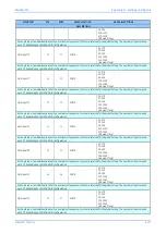
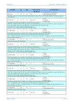
Allows specific bit statuses to be inserted directly into the InterMiCOM message, to substitute real data. This is used for testing purposes.
Loopback Status
15
52
OK
Fail
SCC Absent
[Indexed String]
Indicates the status of the InterMiCOM loopback mode
OK = Loopback software (and hardware) is working correctly
FAIL = Loopback mode failure
Unavailable = Hardware error present.
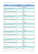
INTERMICOM CONF
16
00
This column is only visible if the model number supports InterMiCOM and second rear comms board is fitted.
IM Msg Alarm Lvl
16
01
25
From 0 to 100 in steps of 0.1
[Courier Number (percentage)]
Setting that is used to alarm for poor channel quality. If during the fixed 1.6s window the ratio of invalid messages to the total number of
messages that should be received (based upon the ‘Baud Rate’ setting) exceeds the above threshold, a ‘Message Fail’ alarm will be issued.
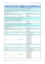
IM1 Cmd Type
16
10
Blocking
Disabled
Direct
Blocking
[Indexed String]
Setting that defines the operative mode of the InterMiCOM_1 signal.
Selecting the channel response for this bit to Blocking allows fastest signalling, whereas setting to Direct offers higher security at the
expense of speed.
Selecting the channel response for this bit to Permissive offers higher dependability
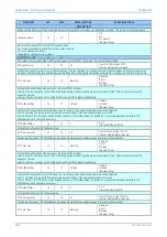
IM1 FallBackMode
16
11
Default
Default
Latched
[Indexed String]
Setting that defines the status of IM1 signal in case of heavy noise and message synchronization being lost.
If set to ‘Latching’ the last valid IM1 status will be maintained until the new valid message is received.
If set to ‘Default’, the IM1 status, pre-defined by the user in ‘IM1 DefaultValue’ cell will be set. A new valid message will replace ‘IM1
DefaultValue’, once the channel recovers.
IM1 DefaultValue
16
12
1
0 or 1
[Unsigned Integer(16 bit)]
Setting that defines the IM1 fallback status.
IM1 FrameSyncTim
16
13
1.5
From 0.01 to 1 in steps of 0.01
[Courier Number (time-seconds)]
Time delay after which ’IM1 DefaultValue’ is applied, providing that no valid message is received in the meantime.
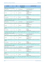
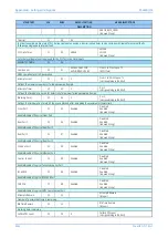
IM2 Cmd Type
16
18
Blocking
Disabled
Direct
Blocking
[Indexed String]
Setting that defines the operative mode of the InterMiCOM_2 signal.
Selecting the channel response for this bit to Blocking allows fastest signalling, whereas setting to Direct offers higher security at the
expense of speed.
Selecting the channel response for this bit to Permissive offers higher dependability
IM2 FallBackMode
16
19
Default
Default
Latched
[Indexed String]
Setting that defines the status of IM2 signal in case of heavy noise and message synchronization being lost.
If set to ‘Latching’ the last valid IM2 status will be maintained until the new valid message is received.
If set to ‘Default’, the IM2 status, pre-defined by the user in ‘IM2 DefaultValue’ cell will be set. A new valid message will replace ‘IM2
DefaultValue’, once the channel recovers.
IM2 DefaultValue
16
1A
1
0 or 1
[Unsigned Integer(16 bit)]
Setting that defines the IM2 fallback status.
IM2 FrameSyncTim
16
1B
1.5
From 0.01 to 1 in steps of 0.01
[Courier Number (time-seconds)]
Time delay after which ’IM2 DefaultValue’ is applied, providing that no valid message is received in the meantime.
IM3 Cmd Type
16
20
Blocking
Disabled
Direct
Blocking
[Indexed String]
Содержание P4A
Страница 2: ......
Страница 20: ...Contents P54A B C E xviii P54xMED TM EN 1 ...
Страница 27: ...CHAPTER 1 INTRODUCTION ...
Страница 28: ...Chapter 1 Introduction P54A B C E 2 P54xMED TM EN 1 ...
Страница 38: ...Chapter 1 Introduction P54A B C E 12 P54xMED TM EN 1 ...
Страница 39: ...CHAPTER 2 SAFETY INFORMATION ...
Страница 40: ...Chapter 2 Safety Information P54A B C E 14 P54xMED TM EN 1 ...
Страница 52: ...Chapter 2 Safety Information P54A B C E 26 P54xMED TM EN 1 ...
Страница 53: ...CHAPTER 3 HARDWARE DESIGN ...
Страница 54: ...Chapter 3 Hardware Design P54A B C E 28 P54xMED TM EN 1 ...
Страница 86: ...Chapter 3 Hardware Design P54A B C E 60 P54xMED TM EN 1 ...
Страница 87: ...CHAPTER 4 SOFTWARE DESIGN ...
Страница 88: ...Chapter 4 Software Design P54A B C E 62 P54xMED TM EN 1 ...
Страница 99: ...CHAPTER 5 CONFIGURATION ...
Страница 100: ...Chapter 5 Configuration P54A B C E 74 P54xMED TM EN 1 ...
Страница 120: ...Chapter 5 Configuration P54A B C E 94 P54xMED TM EN 1 ...
Страница 121: ...CHAPTER 6 CURRENT DIFFERENTIAL PROTECTION ...
Страница 122: ...Chapter 6 Current Differential Protection P54A B C E 96 P54xMED TM EN 1 ...
Страница 149: ...CHAPTER 7 AUTORECLOSE ...
Страница 150: ...Chapter 7 Autoreclose P54A B C E 124 P54xMED TM EN 1 ...
Страница 207: ...CHAPTER 8 CB FAIL PROTECTION ...
Страница 208: ...Chapter 8 CB Fail Protection P54A B C E 182 P54xMED TM EN 1 ...
Страница 219: ...CHAPTER 9 CURRENT PROTECTION FUNCTIONS ...
Страница 220: ...Chapter 9 Current Protection Functions P54A B C E 194 P54xMED TM EN 1 ...
Страница 244: ...Chapter 9 Current Protection Functions P54A B C E 218 P54xMED TM EN 1 ...
Страница 247: ...CHAPTER 10 VOLTAGE PROTECTION FUNCTIONS ...
Страница 248: ...Chapter 10 Voltage Protection Functions P54A B C E 222 P54xMED TM EN 1 ...
Страница 261: ...CHAPTER 11 FREQUENCY PROTECTION FUNCTIONS ...
Страница 262: ...Chapter 11 Frequency Protection Functions P54A B C E 236 P54xMED TM EN 1 ...
Страница 268: ...Chapter 11 Frequency Protection Functions P54A B C E 242 P54xMED TM EN 1 ...
Страница 269: ...CHAPTER 12 MONITORING AND CONTROL ...
Страница 270: ...Chapter 12 Monitoring and Control P54A B C E 244 P54xMED TM EN 1 ...
Страница 300: ...Chapter 12 Monitoring and Control P54A B C E 274 P54xMED TM EN 1 ...
Страница 301: ...CHAPTER 13 SUPERVISION ...
Страница 302: ...Chapter 13 Supervision P54A B C E 276 P54xMED TM EN 1 ...
Страница 312: ...Chapter 13 Supervision P54A B C E 286 P54xMED TM EN 1 ...
Страница 323: ...CHAPTER 14 DIGITAL I O AND PSL CONFIGURATION ...
Страница 324: ...Chapter 14 Digital I O and PSL Configuration P54A B C E 298 P54xMED TM EN 1 ...
Страница 336: ...Chapter 14 Digital I O and PSL Configuration P54A B C E 310 P54xMED TM EN 1 ...
Страница 337: ...CHAPTER 15 FIBRE TELEPROTECTION ...
Страница 338: ...Chapter 15 Fibre Teleprotection P54A B C E 312 P54xMED TM EN 1 ...
Страница 354: ...Chapter 15 Fibre Teleprotection P54A B C E 328 P54xMED TM EN 1 ...
Страница 355: ...CHAPTER 16 ELECTRICAL TELEPROTECTION ...
Страница 356: ...Chapter 16 Electrical Teleprotection P54A B C E 330 P54xMED TM EN 1 ...
Страница 366: ...Chapter 16 Electrical Teleprotection P54A B C E 340 P54xMED TM EN 1 ...
Страница 367: ...CHAPTER 17 COMMUNICATIONS ...
Страница 368: ...Chapter 17 Communications P54A B C E 342 P54xMED TM EN 1 ...
Страница 439: ...CHAPTER 18 CYBER SECURITY ...
Страница 440: ...Chapter 18 Cyber Security P54A B C E 414 P54xMED TM EN 1 ...
Страница 457: ...CHAPTER 19 INSTALLATION ...
Страница 458: ...Chapter 19 Installation P54A B C E 432 P54xMED TM EN 1 ...
Страница 469: ...5 2 CASE DIMENSIONS 60TE E01409 Figure 197 60TE case dimensions P54A B C E Chapter 19 Installation P54xMED TM EN 1 443 ...
Страница 471: ...CHAPTER 20 COMMISSIONING INSTRUCTIONS ...
Страница 472: ...Chapter 20 Commissioning Instructions P54A B C E 446 P54xMED TM EN 1 ...
Страница 513: ...CHAPTER 21 MAINTENANCE AND TROUBLESHOOTING ...
Страница 514: ...Chapter 21 Maintenance and Troubleshooting P54A B C E 488 P54xMED TM EN 1 ...
Страница 530: ...Chapter 21 Maintenance and Troubleshooting P54A B C E 504 P54xMED TM EN 1 ...
Страница 531: ...CHAPTER 22 TECHNICAL SPECIFICATIONS ...
Страница 532: ...Chapter 22 Technical Specifications P54A B C E 506 P54xMED TM EN 1 ...
Страница 558: ...Chapter 22 Technical Specifications P54A B C E 532 P54xMED TM EN 1 ...
Страница 559: ...APPENDIX A ORDERING OPTIONS ...
Страница 560: ...Appendix A Ordering Options P54A B C E P54xMED TM EN 1 ...
Страница 565: ...APPENDIX B SETTINGS AND SIGNALS ...
Страница 566: ...Appendix B Settings and Signals P54A B C E P54xMED TM EN 1 ...
Страница 790: ...Appendix B Settings and Signals P54A B C E B224 P54xMED TM EN 1 ...
Страница 835: ...APPENDIX C WIRING DIAGRAMS ...
Страница 836: ...Appendix C Wiring Diagrams P54A B C E P54xMED TM EN 1 ...
Страница 849: ......