


P54A/B/C/E
Appendix B - Settings and Signals
P54xMED-TM-EN-1
B25
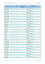
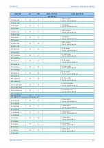
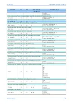
MENU TEXT
COL
ROW
DEFAULT SETTING
AVAILABLE OPTIONS
DESCRIPTION
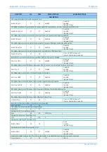
If Rst CB mon LO by is set to CB close then CB mon LO RstDly timer allows reset of CB lockout state after set time delay
Autoreclose Mode
07
0B
No Operation
No Operation
In Service
Out of Service
[Indexed String]
Command to changes state of Auto-Reclose, In Service or Out of Service
AR Status
07
0E
Out of Service
In Service
[Indexed String]
Status of the Auto Reclose - In Service / Out of service
CB Status Input
07
11
52B 1 pole
None
52A 3 pole
52B 3 pole
52A & 52B 3 pole
52A 1 pole
52B 1 pole
52A & 52B 1 pole
[Indexed String]
Setting to define the type of circuit breaker contacts that will be used for the circuit breaker control logic. Form A contacts match the status
of the circuit breaker primary contacts, form B are opposite to the breaker status.
When 1 pole is selected, individual contacts must be assigned in the Programmable Scheme Logic for phase A, phase B, and phase C. Setting
3 pole means that only a single contact is used, common to all 3 poles.
CB Status Time
07
7F
5
From 0.1 to 5 in steps of 0.01
[Courier Number (time-seconds)]
Under healthy conditions the circuit breaker auxiliary contacts will be in opposite states. Should both sets of contacts be open or closed, it
indicates that either the contacts, or the wiring, or the circuit breaker are defective and an alarm will be issued after CB Status Time delay.
The time delay is set to avoid unwanted operation during normal switching duties.
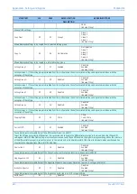
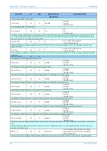
Reset AROK Ind
07
82
No
No
Yes
[Indexed String]
If Res AROK by UI is set to Enabled, this command provides a pulse to reset the successful AR indication for both CB's
Reset CB LO
07
83
No
No
Yes
[Indexed String]
If Res LO by UI is set to Enabled, this command provides a pulse to reset the lockout for CB.
Note: This requires the condition that caused the lockout to have been cleared.
CB Total Shots
07
85
CB Total Shots
[Unsigned Integer (16 bits)]
Indicates the total number of CB reclosures
CB SUCC SPAR
07
86
CB SUCC SPAR
[Unsigned Integer (16 bits)]
Indicates the total number of CB successful 1 pole reclosures
CB SUCC3PARShot1
07
87
CB SUCC3PARShot1
[Unsigned Integer (16 bits)]
Indicates the total number of CB successful 3 pole reclosures at 1st shot
CB SUCC3PARShot2
07
88
CB SUCC3PARShot2
[Unsigned Integer (16 bits)]
Indicates the total number of CB successful 3 pole reclosures at 2nd shot
CB SUCC3PARShot3
07
89
CB SUCC3PARShot3
[Unsigned Integer (16 bits)]
Indicates the total number of CB successful 3 pole reclosures at 3rd shot
CB SUCC3PARShot4
07
8A
CB SUCC3PARShot4
[Unsigned Integer (16 bits)]
Indicates the total number of CB successful 3 pole reclosures at 4th shot
CB Failed Shots
07
8B
CB Failed Shots
[Unsigned Integer (16 bits)]
Indicates the total number of CB failed reclose cycles
Reset CB Shots
07
8C
No
No
Yes
[Indexed String]
Содержание P4A
Страница 2: ......
Страница 20: ...Contents P54A B C E xviii P54xMED TM EN 1 ...
Страница 27: ...CHAPTER 1 INTRODUCTION ...
Страница 28: ...Chapter 1 Introduction P54A B C E 2 P54xMED TM EN 1 ...
Страница 38: ...Chapter 1 Introduction P54A B C E 12 P54xMED TM EN 1 ...
Страница 39: ...CHAPTER 2 SAFETY INFORMATION ...
Страница 40: ...Chapter 2 Safety Information P54A B C E 14 P54xMED TM EN 1 ...
Страница 52: ...Chapter 2 Safety Information P54A B C E 26 P54xMED TM EN 1 ...
Страница 53: ...CHAPTER 3 HARDWARE DESIGN ...
Страница 54: ...Chapter 3 Hardware Design P54A B C E 28 P54xMED TM EN 1 ...
Страница 86: ...Chapter 3 Hardware Design P54A B C E 60 P54xMED TM EN 1 ...
Страница 87: ...CHAPTER 4 SOFTWARE DESIGN ...
Страница 88: ...Chapter 4 Software Design P54A B C E 62 P54xMED TM EN 1 ...
Страница 99: ...CHAPTER 5 CONFIGURATION ...
Страница 100: ...Chapter 5 Configuration P54A B C E 74 P54xMED TM EN 1 ...
Страница 120: ...Chapter 5 Configuration P54A B C E 94 P54xMED TM EN 1 ...
Страница 121: ...CHAPTER 6 CURRENT DIFFERENTIAL PROTECTION ...
Страница 122: ...Chapter 6 Current Differential Protection P54A B C E 96 P54xMED TM EN 1 ...
Страница 149: ...CHAPTER 7 AUTORECLOSE ...
Страница 150: ...Chapter 7 Autoreclose P54A B C E 124 P54xMED TM EN 1 ...
Страница 207: ...CHAPTER 8 CB FAIL PROTECTION ...
Страница 208: ...Chapter 8 CB Fail Protection P54A B C E 182 P54xMED TM EN 1 ...
Страница 219: ...CHAPTER 9 CURRENT PROTECTION FUNCTIONS ...
Страница 220: ...Chapter 9 Current Protection Functions P54A B C E 194 P54xMED TM EN 1 ...
Страница 244: ...Chapter 9 Current Protection Functions P54A B C E 218 P54xMED TM EN 1 ...
Страница 247: ...CHAPTER 10 VOLTAGE PROTECTION FUNCTIONS ...
Страница 248: ...Chapter 10 Voltage Protection Functions P54A B C E 222 P54xMED TM EN 1 ...
Страница 261: ...CHAPTER 11 FREQUENCY PROTECTION FUNCTIONS ...
Страница 262: ...Chapter 11 Frequency Protection Functions P54A B C E 236 P54xMED TM EN 1 ...
Страница 268: ...Chapter 11 Frequency Protection Functions P54A B C E 242 P54xMED TM EN 1 ...
Страница 269: ...CHAPTER 12 MONITORING AND CONTROL ...
Страница 270: ...Chapter 12 Monitoring and Control P54A B C E 244 P54xMED TM EN 1 ...
Страница 300: ...Chapter 12 Monitoring and Control P54A B C E 274 P54xMED TM EN 1 ...
Страница 301: ...CHAPTER 13 SUPERVISION ...
Страница 302: ...Chapter 13 Supervision P54A B C E 276 P54xMED TM EN 1 ...
Страница 312: ...Chapter 13 Supervision P54A B C E 286 P54xMED TM EN 1 ...
Страница 323: ...CHAPTER 14 DIGITAL I O AND PSL CONFIGURATION ...
Страница 324: ...Chapter 14 Digital I O and PSL Configuration P54A B C E 298 P54xMED TM EN 1 ...
Страница 336: ...Chapter 14 Digital I O and PSL Configuration P54A B C E 310 P54xMED TM EN 1 ...
Страница 337: ...CHAPTER 15 FIBRE TELEPROTECTION ...
Страница 338: ...Chapter 15 Fibre Teleprotection P54A B C E 312 P54xMED TM EN 1 ...
Страница 354: ...Chapter 15 Fibre Teleprotection P54A B C E 328 P54xMED TM EN 1 ...
Страница 355: ...CHAPTER 16 ELECTRICAL TELEPROTECTION ...
Страница 356: ...Chapter 16 Electrical Teleprotection P54A B C E 330 P54xMED TM EN 1 ...
Страница 366: ...Chapter 16 Electrical Teleprotection P54A B C E 340 P54xMED TM EN 1 ...
Страница 367: ...CHAPTER 17 COMMUNICATIONS ...
Страница 368: ...Chapter 17 Communications P54A B C E 342 P54xMED TM EN 1 ...
Страница 439: ...CHAPTER 18 CYBER SECURITY ...
Страница 440: ...Chapter 18 Cyber Security P54A B C E 414 P54xMED TM EN 1 ...
Страница 457: ...CHAPTER 19 INSTALLATION ...
Страница 458: ...Chapter 19 Installation P54A B C E 432 P54xMED TM EN 1 ...
Страница 469: ...5 2 CASE DIMENSIONS 60TE E01409 Figure 197 60TE case dimensions P54A B C E Chapter 19 Installation P54xMED TM EN 1 443 ...
Страница 471: ...CHAPTER 20 COMMISSIONING INSTRUCTIONS ...
Страница 472: ...Chapter 20 Commissioning Instructions P54A B C E 446 P54xMED TM EN 1 ...
Страница 513: ...CHAPTER 21 MAINTENANCE AND TROUBLESHOOTING ...
Страница 514: ...Chapter 21 Maintenance and Troubleshooting P54A B C E 488 P54xMED TM EN 1 ...
Страница 530: ...Chapter 21 Maintenance and Troubleshooting P54A B C E 504 P54xMED TM EN 1 ...
Страница 531: ...CHAPTER 22 TECHNICAL SPECIFICATIONS ...
Страница 532: ...Chapter 22 Technical Specifications P54A B C E 506 P54xMED TM EN 1 ...
Страница 558: ...Chapter 22 Technical Specifications P54A B C E 532 P54xMED TM EN 1 ...
Страница 559: ...APPENDIX A ORDERING OPTIONS ...
Страница 560: ...Appendix A Ordering Options P54A B C E P54xMED TM EN 1 ...
Страница 565: ...APPENDIX B SETTINGS AND SIGNALS ...
Страница 566: ...Appendix B Settings and Signals P54A B C E P54xMED TM EN 1 ...
Страница 790: ...Appendix B Settings and Signals P54A B C E B224 P54xMED TM EN 1 ...
Страница 835: ...APPENDIX C WIRING DIAGRAMS ...
Страница 836: ...Appendix C Wiring Diagrams P54A B C E P54xMED TM EN 1 ...
Страница 849: ......