


GE Multilin
N60 Network Stability and Synchrophasor Measurement System
6-17
6 ACTUAL VALUES
6.3 METERING
6
6.3.3 SENSITIVE DIRECTIONAL POWER
PATH: ACTUAL VALUES
ÖØ
METERING
ÖØ
SENSITIVE DIRECTIONAL POWER
The effective operating quantities of the sensitive directional power elements are displayed here. The display may be useful
to calibrate the feature by compensating the angular errors of the CTs and VTs with the use of the
RCA
and
CALIBRATION
settings.
6.3.4 SYNCHROCHECK
PATH: ACTUAL VALUES
ÖØ
METERING
ÖØ
SYNCHROCHECK
Ö
SYNCHROCHECK 1(2)
The actual values menu for synchrocheck 2 is identical to that of synchrocheck 1. If a synchrocheck function setting is "Dis-
abled", the corresponding actual values menu item will not be displayed.
6.3.5 TRACKING FREQUENCY
PATH: ACTUAL VALUES
ÖØ
METERING
ÖØ
TRACKING FREQUENCY
The tracking frequency is displayed here. The frequency is tracked based on the selection of the reference source with the
FREQUENCY AND PHASE REFERENCE
setting in the
SETTINGS
ÖØ
SYSTEM SETUP
ÖØ
POWER SYSTEM
menu. Refer to the
Power System
section of chapter 5 for additional details.
6.3.6 FLEXELEMENTS™
PATH: ACTUAL VALUES
ÖØ
METERING
ÖØ
FLEXELEMENTS
Ö
FLEXELEMENT 1(16)
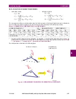
The operating signals for the FlexElements™ are displayed in pu values using the following definitions of the base units.
SENSITIVE
DIRECTIONAL POWER
DIRECTIONAL POWER 1
3
Φ
: 0.000 W
MESSAGE
DIRECTIONAL POWER 2
3
Φ
: 0.000 W
SYNCHROCHECK 1
SYNCHROCHECK 1 DELTA
VOLT: 0.000
V
MESSAGE
SYNCHROCHECK 1 DELTA
PHASE: 0.0°
MESSAGE
SYNCHROCHECK 1 DELTA
FREQ: 0.00
Hz
TRACKING FREQUENCY
TRACKING FREQUENCY:
60.00 Hz
FLEXELEMENT 1
FLEXELEMENT 1
OpSig: 0.000 pu
Table 6–2: FLEXELEMENT™ BASE UNITS (Sheet 1 of 2)
dcmA
BASE = maximum value of the
DCMA INPUT MAX
setting for the two transducers configured
under the +IN and –IN inputs.
FREQUENCY
f
BASE
= 1 Hz
PHASE ANGLE
ϕ
BASE
= 360 degrees (see the UR angle referencing convention)
POWER FACTOR
PF
BASE
= 1.00
RTDs
BASE = 100°C
SENSITIVE DIR POWER
(Sns Dir Power)
P
BASE
= maximum value of 3
×
V
BASE
×
I
BASE
for the +IN and –IN inputs of the sources
configured for the sensitive power directional element(s).
Содержание N60 UR Series
Страница 2: ......
Страница 4: ......
Страница 330: ...6 24 N60 Network Stability and Synchrophasor Measurement System GE Multilin 6 5 PRODUCT INFORMATION 6 ACTUAL VALUES 6 ...
Страница 340: ...7 10 N60 Network Stability and Synchrophasor Measurement System GE Multilin 7 2 TARGETS 7 COMMANDS AND TARGETS 7 ...
Страница 436: ...B 78 N60 Network Stability and Synchrophasor Measurement System GE Multilin B 4 MEMORY MAPPING APPENDIXB B ...
Страница 474: ...D 10 N60 Network Stability and Synchrophasor Measurement System GE Multilin D 1 IEC 60870 5 104 PROTOCOL APPENDIXD D ...
Страница 486: ...E 12 N60 Network Stability and Synchrophasor Measurement System GE Multilin E 2 DNP POINT LISTS APPENDIXE E ...