background image

GEK-113188A

MIGII Digital Protection for Electrical Machines 

9-15

9 RELAY COMMISSIONING

9.14 PHASE TOC ELEMENT (51P)

9

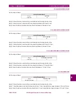
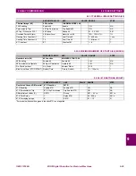
9.14.4 ANSI INVERSE CURVE

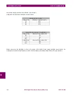
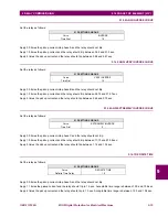
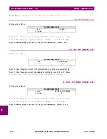
Set the relay as follows:  

Apply 0.9 times the pickup current into phase A and the relay should not trip.

Apply 1.5 times the pickup current and the relay should trip between 36.2 and 51.3 sec.

Apply 5 times the pickup current and the relay should trip between 3.88 and 4.27 sec.

9.14.5 ANSI VERY INVERSE CURVE

Set the relay as follows:

Apply 0.9 times the pickup current into phase B and the relay should not trip.

Apply 1.5 times the pickup current and the relay should trip between 26.72 and 37.27 sec.

Apply 5 times the pickup current and the relay should trip between 2.46 and 2.75 sec.

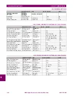
9.14.6 ANSI EXTREMELY INVERSE CURVE

Set the relay as follows: 

Apply 0.9 times the pickup current into phase C and the relay should not trip.

Apply 1.5 times the pickup current and the relay should trip between 17.19 and 23.58 sec.

Apply 5 times the pickup current and the relay should trip between 1.14 and 1.34 sec.

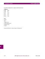
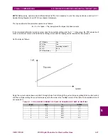
9.14.7 DEFINITE TIME

Set the relay as follows:

Apply 0.9 times the pickup current into phase A and the relay should not trip.

Apply 1.1 times the pickup current and the relay should trip in 1.0 sec. Acceptable time range is between 1.00 and 1.06 sec.

Apply 4 times the pickup current and the relay should trip in 1.0 sec. Acceptable time range is between 1.00 and 1.06 sec.

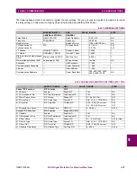
51P SETTINGS GROUP

Curve

INVERSE

Time Dial

10

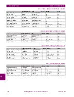
51P SETTINGS GROUP

Curve

VERY INVERSE

Time Dial

10

51P SETTINGS GROUP

Curve

EXTREMELY INVERSE

Time Dial

5

51P SETTINGS GROUP

Curve

DEFINITE TIME

Definite Time Delay

1.0

Содержание Multilin MIGII

Страница 1: ...emultilin ge com Internet www GEMultilin com Copyright 2005 GE Multilin MIGII Digital Protection for Electrical Machines Instruction manual GEK 113188A GE Multilin Avda Pinoa 10 48170 Zamudio SPAIN Tel 34 94 485 88 00 Fax 34 94 485 88 45 E mail gemultilin euro ge com g GE Consumer Industrial Multilin ...

Страница 2: ......

Страница 3: ... 2 8 2 5 3 GROUND TIME OVERCURRENT ELEMENT 51G 2 8 2 5 4 GROUND INSTANTANEOUS OVERCURRENT ELEMENT 50G 2 8 2 6 THERMAL IMAGE ELEMENT 49 2 7 NEGATIVE SEQUENCE ELEMENT 46 2 8 UNDERCURRENT 37 MIGII Q 2 9 LOCKED ROTOR 48 MIGII Q 2 10 RESTRICTED GROUND DIFFERENTIAL ELEMENT 87R MIGII Q 2 11 MAXIMUM NUMBER OF STARTS 66 2 12 MULTIPLE SETTING GROUPS 2 13 MEASUREMENT AND SELF TEST 2 13 1 MEASUREMENT 2 18 2 1...

Страница 4: ...OPEN 4 3 4 2 3 PROPERTIES 4 4 4 2 4 GET INFO FROM RELAY 4 4 4 2 5 SEND INFO TO RELAY 4 4 4 2 6 PRINT SETUP 4 5 4 2 7 PRINT PREVIEW 4 5 4 2 8 PRINT 4 6 4 2 9 CLOSE 4 6 4 3 SETPOINT 4 3 1 SETTINGS 4 7 4 3 2 MAIN SETTINGS 4 9 4 3 3 ADVANCED SETTINGS 4 9 4 3 4 RELAY CONFIGURATION 4 10 4 3 5 LOGIC CONFIGURATION 4 12 4 3 6 CLOCK 4 13 4 4 ACTUAL 4 4 1 ACTUAL VALUES 4 14 4 4 2 EVENT RECORDER 4 15 4 4 3 WA...

Страница 5: ...MIGII Q 5 18 5 3 10 F87R MIGII P 5 19 5 3 11 USER CURVE 5 19 5 3 12 EVENTS AND OSCILLOGRAPHY MASKS 5 20 5 3 13 OSCILLOGRAPHY MASKS 5 22 5 3 14 MIGII INTERNAL STATUSES 5 22 5 4 TIME SYNCHRONIZATION 6 I 0 CONFIGURATION 6 1 INPUT CONFIGURATION 6 1 1 DESCRIPTION OF INPUTS 6 1 6 1 2 INPUT ELEMENTS 6 4 6 2 OUTPUTS AND LEDS CONFIGURATION 6 2 1 DESCRIPTION OF OUTPUTS AND LEDS 6 5 6 2 2 OUTPUT AND LED ELEM...

Страница 6: ...VE 9 16 9 15 3 IEC EXTREMELY INVERSE CURVE 9 16 9 15 4 ANSI INVERSE CURVE 9 17 9 15 5 ANSI VERY INVERSE CURVE 9 17 9 15 6 ANSI EXTREMELY INVERSE CURVE 9 17 9 15 7 DEFINITE TIME 9 17 9 16 THERMAL IMAGE ELEMENT 49 9 16 1 DIRECT SEQUENCE TEST 9 18 9 16 2 INVERSE SEQUENCE TEST 9 19 9 16 3 SINGLE PHASE SIGNAL TEST 9 19 9 17 LOCKED ROTOR 48 9 18 RESTRICTED GROUND DIFFERENTIAL CURRENT 87R 9 19 UNDERCURRE...

Страница 7: ...0 INSTALLATION AND MAINTENANCE 10 1 INSTALLATION 10 2 GROUND CONNECTION AND DISTURBANCES SUPPRESSION 10 3 MAINTENANCE 10 4 CLEANING INSTRUCTIONS 11 MII FAMILY FAQ FREQUENTLY ASKED QUESTIONS 11 1 MIGII FAQ 12 MIFII DO S AND DON TS 12 1 DO S 12 2 DON TS 13 TROUBLESHOOTING GUIDE 13 1 MIGII TROUBLESHOOTING GUIDE A THERMAL IMAGE UNIT A 1 INTRODUCTION A 2 OPERATING PRINCIPLE A 3 ALGORITHMS A 4 DIGITAL T...

Страница 8: ...S C 8 MODBUS MAP STATUS D APPLICATION NOTES D 1 TRIP CIRCUIT SUPERVISION FOR MII FAMILY RELAYS D 1 1 SETTINGS AND CONFIGURATION 17 3 E MODEM CONNECTION E 1 HAYES MODEM E 2 V 25BIS MODEM E 3 SAMPLES OF SETTINGS FOR PARTICULAR MODEMS E 3 1 SPORTSTER FLASH X2 MODEM HAYES 18 4 E 3 2 ZOOM PKT14 4 18 5 E 3 3 MODEM SATELSA MGD 2400 DHE V 25BIS 18 6 ...

Страница 9: ...llowing chapter for information to help guide you through the initial installation procedures of your new relay CAUTION THE OPERATOR OF THIS INSTRUMENT IS ADVISED THAT IF THE EQUIPMENT IS USED IN A MANNER NOT SPECIFIED IN THIS MANUAL THE PROTECTION PROVIDED BY THE EQUIPMENT MAY BE IMPAIRED INSTALLATION MUST BE ACCORDING TO THE NATIONAL ELECTRIC CODE OF THE APPROPRIATE COUNTRY ...

Страница 10: ...for physical damage Check the label at the side of the relay and check that the relay model is the same model ordered Figure 1 1 RELAY IDENTIFICATION LABEL A4454P23 Ensure that the mounting screws have been included with the relay For product information instruction manual updates and the latest software updates please visit the GE Multilin Home Page www GEindustrial com multilin ...

Страница 11: ...lin tech euro ge com AMERICA ASIA AND AUSTRALIA GE MULTILIN 215 Anderson Avenue L6E 1B3 Markham ON CANADA Tel 1 905 294 6222 Fax 1 905 201 2098 E mail multilin tech ge com The information provided herein does not intend to cover all details of variations of the equipment nor does it take into account the circumstances that may be present in your installation operating or maintenance activities Sho...

Страница 12: ... you want to communicate with the relay using a computer through the front serial port please ensure that the computer is grounded to the same ground as the relay In case of using a portable computer it is recommended to not have it connected to its power supply as in many cases they are not correctly grounded either due to the power supply itself or to the connector cables used Powering the porta...

Страница 13: ...Click the Install Now button and follow the installation instructions to install the no charge EnerVista software 3 When installation is complete start the EnerVista Launchpad application 4 Click the IED Setup section of the Launch Pad window Figure 1 3 5 In the EnerVista Launch Pad window click the Add Product button and select the relay from the Install Software window as shown below Select the ...

Страница 14: ...ption is selected choose from the list the software program related to the specific model and click the Download Now button to obtain the installation program 7 When EnerVista detects that there is already a version of the program in the Software Library you can choose whether to install it directly or to check for more versions Figure 1 5 ...

Страница 15: ...r the different versions of set up program from the Web Figure 1 6 9 EnerVista Launchpad will obtain the installation program from the Web If the version you already have is the last one on the Web the following screen will appear Figure 1 7 10 If there were more versions on the Web EnerVista will then show the user the different setup programs available for upgrade with their version size and rel...

Страница 16: ...installed in the directory indicated and the installation program will automatically create icons and add ENERVISTA MII SETUP to the Windows start menu 14 Follow the on screen instructions to install the ENERVISTA MII SETUP software When the Welcome window appears click on Next to continue with the installation procedure Figure 1 8 15 When the Choose Destination Location window appears and if the ...

Страница 17: ...lt program group where the application will be added to is shown in the Selected Program Folder window Click Next to begin the installation process and all the necessary program files will be copied into the chosen directory Figure 1 10 17 To finish with the installation process select the desired language for startup Figure 1 11 ...

Страница 18: ...trical Machines GEK 113188A 1 2 ENERVISTA MII SETUP SOFTWARE 1 GETTING STARTED 1 18 Click Finish to end the installation The MII device will be added to the list of installed IEDs in the EnerVista Launchpad window as shown below Figure 1 12 ...

Страница 19: ...rter box is required GE Multilin offers F485 DAC300 and RS232 485 converters This converter box is connected to the computer using a straight through serial cable A shielded twisted pair 20 22 or 24 AWG 0 25 0 34 or 0 5 mm2 cable is used to connect the converter box to the relay rear communication terminals The converter box GND terminals are connected to the relay SDA SDB GND terminals respective...

Страница 20: ...e current value for each phase Ia Ib Ic Ig Pressing the Menu button accesses the second level To access information within the same hierarchical level horizontal movement push the up down arrow buttons To access the third level push the Enter button when the desired heading is shown in the display To return back to the previous level from the third to the second level or from the second to the fir...

Страница 21: ...ercurrent 37 MIGII Q Maximum No of starts 66 MIGII Q Locked Rotor 48 MIGII Q Restricted ground differential unit 87R MIGII P CONTROL 2 Setting groups Open close breaker operations METERING Phase and ground currents Thermal image INPUTS OUTPUTS 4 Current inputs 3 phases 1 ground Programmable digital inputs and outputs COMMUNICATIONS Front RS232 port Rear RS485 port USER INTERFACE 2x16 LCD Display 6...

Страница 22: ...t a PC for programming settings monitoring actual values and for retrieving stored information list of events oscillography etc All serial ports use the Modbus RTU protocol and may be connected to system computers with baud rates from 300 600 1200 4800 9600 and 19200 bps The rear RS485 port can be converted into an RS232 port or into a fiber optic plastic or glass serial port by using GE Multilin ...

Страница 23: ...3188A MIGII Digital Protection for Electrical Machines 2 3 2 PRODUCT DESCRIPTION 2 2 INTRO 2 Figure 2 2 MIGII Q BLOCK DIAGRAM FOR MOTOR APPLICATIONS Figure 2 3 MIGII BLOCK DIAGRAM FOR TRANSFORMER APPLICATIONS ...

Страница 24: ...d When the access is local by the RS232 port the back port is disabled and the relay will not serve any petition or command sent by the rear port When the access is local by keypad the back port is not disabled and actual values can be read but setting changes and operations will not be allowed by the back port Setting changes either by keypad and display or by communications are password protecte...

Страница 25: ...easured magnitude as it happens with other algorithms such as DFT which are affected by frequency The relay calculates for each measure semi cycle the maximum or minimum value The effective measure is calculated as follows In order to guarantee proper operation of the protection elements independently from the frequency timed overcurrent 51P 51G undercurrent 37 and locked rotor 48 protection eleme...

Страница 26: ...42 While another group complies with ANSI C37 90 standards A time dial can be applied to any of these curves to optimize co ordination with other devices in the net Additionally there is a possibility to define a User s Curve which can be used for both three phase overcurrent and ground elements 2 5 1 1 IEC CURVES Response times for IEC curves are as follows For 1 05 V 20 00 the tripping time will...

Страница 27: ...r V I Ipickup setting 1 05 2 5 1 3 IAC AND USER CURVES 2 5 1 4 USER CURVES Response times for User curve are as follows For 1 05 V 20 00 tripping time will be For V 20 00 tripping time will be the same as for 20 00 times the setting Where CURVE NAME A B C D E Extremely Inverse 0 0399 0 2294 0 5000 3 0094 0 7222 Very Inverse 0 0615 0 7989 0 3400 0 2840 4 0505 Inverse 0 0274 2 2614 0 3000 4 1899 9 1...

Страница 28: ...element 50P can be enabled disabled and set independently from the timed overcurrent unit Settings from this elementallow to set the pickup value from 0 1 to 30 times the rated current or 0 002 1 5 A in case of sensitive ground models and the time delay from 0 00 to 600 00 seconds 2 5 3 GROUND TIME OVERCURRENT ELEMENT 51G The Ground Time Overcurrent element offers the same setting possibilities as...

Страница 29: ...ve sequence values I1 and I2 as follows Where K1 is a constant that overvalues the effect of the negative sequence I2 component and is selectable between 1 and 8 The negative sequence is included in the above formula in order to protect the generator from the effects caused by the system light unbalanced currents such as the ones produced by load unbalance High negative sequence values such as tho...

Страница 30: ...e opposite way to the rotor The flux produced by this current seen from the rotor has a frequency that is twice the synchronous speed as a result of the inverse rotation combined with the direct rotation of the rotor This flux induces currents with twice the nominal frequency whose pellicular effect makes them fluctuate through the rotor surface and in a slighter way through the winding The result...

Страница 31: ...ed to perform a stop or sequential trip of a generator in service Its minimum setting value corresponds to the minimum level of loss in empty of the majority of generators of diverse types This unit can be enabled independently and set as required As other functions its setting is based on the rated current FLC If the current value falls below 5 of the FLC value this protection element will be dis...

Страница 32: ...tect the motor by taking it off line quicker than the thermal model overload curve it may also prevent or limit damage to the driven equipment that may occur if motor starting torque persists on jammed or broken equipment The pickup level should be set higher than the motor loading during normal operations but lower than the motor stall level Normally the delay would be set to the minimum time del...

Страница 33: ...ain level to produce a trip This solution has the inconvenience of reducing the protection sensitivity This is why the 87R element incorporates this supervision function which compares the Idiff magnitude with the maximum phase current Iýmax present all times This slope defines the protection unit sensitivity and is determined by a setting K Therefore If the calculated differential current is high...

Страница 34: ...ssibilities are considered depending on the Supervision by 52B setting in relay generated settings 1 Supervision by 52B NO The motor is considered to be stopped when the average current of the three phases is below 5 of the value set for FLC A start is detected when being the motor stopped according to the above definition the average current of the three phases rises above 7 of FLC 2 Supervision ...

Страница 35: ...rip enable disable by digital input 46 Trip enable disable by digital input 49 Trip enable disable by digital input 87R Trip enable disable by digital input MIGII P 66 Operation enable disable by digital input MIGII Q General trip enable disable by digital input Protection status in service out of service READY Digital output 1 active non active Digital output 2 active non active Digital output 3 ...

Страница 36: ...apacitor backed up RAM memory MIGII functionality related to oscillography is performed from the ENERVISTA MII SETUP program The oscillography record obtained is stored on the PC in a COMTRADE IEEE C37 111 1991 format There are four possible causes that can produce an oscillography trigger 1 Pickup of one of the protection functions 2 Trip of one of the protection functions 3 Oscillography trigger...

Страница 37: ...wo is active at a given time Users can select which setting group is active using a setting sending a command to the relay from the communications program or by a digital input Settings are divided in two different categories Main Settings and Advanced Settings This makes setting the relay extremely simple for those users who want to use just the Main functions of the MIGII relay Users who require...

Страница 38: ...ground currents and Thermal Image Accuracy is 1 of injected current at rated current and 3 of injected current in the complete range 2 13 2 SELF TEST Self monitoring tests are carried out both when the unit is started up and during normal operation Any internal problem detected by the self monitoring function will issue an alarm and the READY output contact will be released indicating an out of se...

Страница 39: ...p has been issued by one of the overcurrent elements 50P 50G 51P 51G UNBALANCE the trip has been issued by the current unbalance element 46 PICKUP Indicates that at least one of the protective elements has picked up LEDs associated to tripping functions are latched and once they have been turned on they remain on until the ESC RESET button is pressed for more than 3 seconds RESET providing that th...

Страница 40: ...IPTION 2 2 14 4 SOFTWARE MIGII units are supplied together with ENERVISTA MII SETUP software a Windows based software that allows communication with the relay for data viewing and retrieval as well as oscillography I O configuration and logical configuration in models where these features are available ...

Страница 41: ...he following table 87R Does not apply for sensitive ground model ACCESSORIES A depth reducing collar can be ordered separately This collar reduces the mounting depth in 63 mm 2 48 inches MIGII E 0 0 0 0 DESCRIPTION APPLICATION P Generator application Q Motor application Curves A ANSI I IEC U IAC PHASE CT 5 CT In 5 A 0 5 12 A 1 CT In 1 A 0 1 2 4 A GROUND CT 5 CT In 5 A 0 5 12 A 1 CT In 1 A 0 1 2 4 ...

Страница 42: ... Level 2 16 1 1 PHASE GROUND INSTANTANEOUS OVERCURRENT 50P 50G Metering Algorithm Pickup Level Dropout Level Level Accuracy Overreach Time Delay Reset Type Timing Accuracy Fundamental 0 1 to 30 0 FLC in steps of 0 01 97 typical of Pickup 3 in the complete range 2 0 00 to 600 00 sec in steps of 0 01 s Instantaneous 50ms for timer set to 0ms 20ms for 3 of total time for timer set to 0ms 2 16 1 2 THE...

Страница 43: ...ipping time accuracy Maximum 1 01 10 FLC in steps of 0 01 0 00 to 600 00 in steps of 0 01 250 ms or 5 2 16 1 5 UNDERCURRENT 37 MIGII Q Metering Algorithm Pickup level Timing Tripping time accuracy Maximum 1 01 10 FLC in steps of 0 01 0 00 to 600 00 in steps of 0 01 250 ms or 5 2 16 1 6 MAXIMUM NUMBER OF STARTS 66 MIGII Q Metering Algorithm Pickup level Start blocking timer Tripping time accuracy F...

Страница 44: ...pending on the selected model 50 60 Hz The unit can be set to 50 or 60 Hz ground secondary 2 16 3 2 DIGITAL INPUTS Voltage Level Recognition Time 300 Vdc maximum 4 ms 2 16 4 1 LOW RANGE Rated DC Voltage Min Max DC Voltage 24 to 48 Vdc 19 58 Vdc 2 16 4 2 HIGH RANGE Rated DC Voltage Min Max DC Voltage Rated AC Voltage Min Max AV Voltage 110 to 250 Vdc 88 300 Vdc 110 to 230 Vac 48 62 Hz 88 264 Vac 48...

Страница 45: ...c 0 4 PF B300 pilot duty Make and Carry 48 A Breaking 4000 VA VOLTAGE MAKE CARRY CONTINUOUS MAKE CARRY 0 2 SEC BREAK MAX LOAD DC Resistive 24 Vdc 16 A 48 A 16 A 384W 48 Vdc 16 A 48 A 2 6 A 125W 125 Vdc 16 A 48 A 0 6 A 75 W 250 Vdc 16 A 48 A 0 5 A 125 W AC Resistive 120 Vac 16 A 48 A 16 A 1920 VA 250 Vac 16 A 48 A 16 A 4000 VA AC Inductive PF 0 4 250 Vac 10 A 30 A 10 A 1000 VA FRONT PORT RS232 300 ...

Страница 46: ...est Level 3 2kV CM 1kV DM IEC 61000 4 6 1996 EN 61000 6 2 2001 Injected RF Signals Immunity Test Level 3 10 V m 0 15 80 MHz IEC 61000 4 11 1994 EN 61000 6 2 2001 Voltage Dips and Interruptions Immunity Tetst Duration and Voltage described in the related report IEC 60255 22 1 1988 1 MHz Burst Disturbance Test Level 3 2 5 kV in common mode and 1 kV in differential mode in the I O terminals specified...

Страница 47: ...es 2 27 2 PRODUCT DESCRIPTION 2 16 TECHNICAL SPECIFICATIONS 2 2 16 9 PRODUCTION TESTS 2 16 10 APPROVALS Manufactured under an ISO9001 Registered system CE Marking Insulation Test IEC255 5 Tested on CTs Power Supply terminals Contact Inputs and Contact Outputs ...

Страница 48: ...2 28 MIGII Digital Protection for Electrical Machines GEK 113188A 2 16 TECHNICAL SPECIFICATIONS 2 PRODUCT DESCRIPTION 2 ...

Страница 49: ...ghly resistive material which guarantees the unit s immunity to all types of EMI RFI ESD interference As well an IP52 IEC 529 protection degree against dust and water through the front and with the relay mounted in the panel The modular design of the relay simplifies repair or replacement of its components without the need to manipulate the wiring These types of operations must be performed exclus...

Страница 50: ...ured to the panel with the 4 M6 screws provided with the unit This allows the user access to the front keypad display and communication port The wiring is at the rear of the unit The drilling dimensions are shown on the drilling dimension diagram Note Dimensions are shown in inches mm Figure 3 2 MOUNTING AND DIMENSIONS DRAWING FOR MIGII MODELS WITH DEPTH REDUCING COLLAR ...

Страница 51: ...crewed to the case that incorporates shorting bars in the current inputs so that it can be extracted without the need to short circuit the current externally A grounded antistatic wristband must be used when manipulating the module in order to avoid electrostatic discharges that may cause damage to the electronic components In a similar way when mounting and dismounting the front of the unit be su...

Страница 52: ...or Electrical Machines GEK 113188A 3 2 WIRING 3 HARDWARE 3 3 2WIRING 3 2 1 TYPICAL WIRING DIAGRAM Recommended cable section 12 16 AWG Copper conductor only Tightening torque 1 2 Nm Figure 3 4 TYPICAL WIRING DIAGRAM FOR MIGII P RELAY ...

Страница 53: ...GEK 113188A MIGII Digital Protection for Electrical Machines 3 5 3 HARDWARE 3 2 WIRING 3 Figure 3 5 TYPICAL WIRING DIAGRAM FOR MIGII Q RELAY ...

Страница 54: ...OWER CAUTION CONTROL POWER SUPPLIED TO THE RELAY MUST MATCH THE RATED VOLTAGE OF THE RELAY IF THE VOLTAGE IS APPLIED TO THE WRONG TERMINALS DAMAGE MAY OCCUR Table 3 1 CONTROL POWER VOLTAGE RANGE RANGE RATED VOLTAGE OPERATION RANGE LO 24 48 Vdc 19 2 57 6 Vdc HI 110 250 Vdc 110 230 Vac 88 300 Vdc 88 264 Vac ...

Страница 55: ...ternal ground connections on the current inputs Current transformers with 1 A or 5 A rated secondary current may be used CAUTION VERIFY THAT YOUR RELAY MODEL CORRESPONDS TO YOUR RATED SECONDARY CURRENT UNMATCHED CTS MAY RESULT IN EQUIPMENT CMAGE OR INADEQUATE PROTECTION The exact placement of a zero sequence CT so that ground fault current will be detected is shown below Twisted pair cabling on th...

Страница 56: ...elays LO model the threshold is set to 12 Vdc For high voltage range relays HI model the voltage threshold is 75 Vdc In case of using AC voltage it must be ensured that there is no voltage less than 10 Vac between the input common terminal A10 and the ground terminal The AC system must be line neutral type and not line line ensuring that the neutral and ground do not differ in more than 10 Vac The...

Страница 57: ...ay is connected to the MIGII output terminal For each output relay it is possible to select which state is preferred to have at the MIGII terminals NC normally closed or NO normally open Next figure shows the PCB of a MIGII relay and the location of the jumpers used to select the configuration of each output contact NO or NC Figure 3 9 PCB SCHEME SHOWING THE JUMPERS TO CONFIGURE THE OUTPUT CONTACT...

Страница 58: ...his case the number of outputs is reduced to three Jx jumper is closed in the factory default configuration It is possible to order relays with Jx removed The figure shows the factory default configuration with Jx Jumper closed It is located on the soldering part of the PCB containing the inputs and outputs Figure 3 10 JX JUMPER The Jx jumper is a tin solder jumper easy to remove using a de solder...

Страница 59: ...rovide one output contact combining OUT1 and OUT2 Group 2 Terminals B9 A7 OUT3 Standard output contact Terminals B10 A7 OUT4 Standard output contact 3 2 6 1 OUTPUT CONFIGURATION AT TERMINALS B8 B7 To have a closed contact across terminals B7 B8 one of the two following procedures should be followed a JX REMOVED AND OUT1 AND OUT2 NORMALLY OPEN OUT1 and OUT2 must operate together to operate like a s...

Страница 60: ...e with this hardware configuration it is necessary to configure by software the OUT1 as NOT ASIGNED so it never change its state and remains closed and OUT2 as required by the application output configuration is only available in models option 1 and 2 b OUT1 NORMALLY OPEN AND OUT2 NORMALLY CLOSED The hardware configuration corresponds to OUT1 NO and OUT2 NC To operate with this hardware configurat...

Страница 61: ... use this interface is a personal computer running the ENERVISTA MII SETUP software Next figure shows the communications cable configuration Figure 3 12 RS232 FRONT PORT CONNECTION WARNING IN ORDER TO PREVENT DAMAGE BOTH TO THE PC SERIAL COMMUNICATIONS PORT AND THE RELAY FRONT RS232 PORT IT IS COMPULSORY TO CONNECT THE RELAY GROUND TO THE SAME GROUND AS THE PC OTHERWISE USE AN UNGROUNDED COMPUTER ...

Страница 62: ... general rule terminals A should be connected to terminals and terminals B to There are exceptions to this rule such as the GE ALPS and DDS family of relays The GND terminal should be connected to the common wire inside the shield when provided Otherwise it should be connected to the shield To avoid loop currents the shield should be grounded at one point only Each relay should also be daisy chain...

Страница 63: ... to configure monitor and manage all MIGII features a Setting files ENERVISTA MII SETUP software provides two ways of working with setting files 1 In off line mode disconnected from the relay creating or editing setting files for a future download to the relay 2 Modifying directly the relay settings while connected to the relay b Configuration The configuration of inputs outputs and LEDs can be mo...

Страница 64: ...nding Otherwise communication may not be possible or the relay and or the computer could be damaged To work online the relay communication parameters e g baud rate relay address and password must match the parameters in the computer The computer parameters can be modified in the Communication Computer menu Refer to the appropriate section in this same chapter for more details 4 1 3 MAIN SCREEN The...

Страница 65: ...fic relay model matching exactly the relay model to which the settings and configuration will later be downloaded The mentioned settings and configuration are related to the default factory settings of the relay Figure 4 2 Once the relay model is selected the software will load the relay structure and will enable the Setpoint Actual Communication View and Help menus for configuration 4 2 2 OPEN Op...

Страница 66: ...on Figure 4 3 Figure 4 3 4 2 4 GET INFO FROM RELAY The File Get info from relay option enables the user to save the relay settings in a file on the hard disk of the computer This file can later be opened offline to review and modify settings and send them again to the relay after the modifications 4 2 5 SEND INFO TO RELAY The File Set info to relay option enables to send to the relay a settings fi...

Страница 67: ...w of the the settings print out It is also provides a quick view of all the relay settings at a glance without having to navigate through the different menu trees From this screen it is also possible to configure the printer that will be used or to directly print the document Double clicking on the document with the left mouse button will enlarge the document view and double clicking with the righ...

Страница 68: ...nes GEK 113188A 4 2 FILE 4 COMMUNICATIONS 4 4 2 8 PRINT The File Print option prints the relay settings using Windows default active printer 4 2 9 CLOSE The File Close option exits the program It does not prompt for confirmation or save the open file ...

Страница 69: ...of this division is to simplify the use of the relay for those users only requiring the basic functionality of the relay Figure 4 6 SETTINGS MENU Once in the corresponding sub menu either Main Settings or Advanced Settings the procedure to enter and modify any setting value is the same Select the settings group the function selected in the example is the 51P Function in a MIF II Edit the setting d...

Страница 70: ...opriate clicking with the mouse on the option desired Numerical Settings For Numerical settings a number must be entered The program shows the minimum and maximum value for each setting and it will not accept any value out of the corresponding range Settings with a set of options For set of options settings a pop up window is shown containing all possible values Select the appropriate one clicking...

Страница 71: ...g groups Group 1 is available in the Main Settings group while Group 2 can be accessed in the Advanced Settings group The setting groups can be selected by digital input through a communications command or from the ENERVISTA MII SETUP or simply selecting it with the relay keypad The setting that shows the active group can be found in General Advanced Settings 4 3 3 ADVANCED SETTINGS 4 3 3 1 ADVANC...

Страница 72: ...ing of the different columns is explained below INPUT LED OUTPUT Designates the respective element I O configuration the appearance and function of this column can be depending on the state of the respective OR checkbox column OR checkbox is not checked the element consists of a drop down list in which the user can select the function that will activate the output or LED or that will be activated ...

Страница 73: ...D will actuate when the conditions are NOT fulfilled NAME the user can write an identifying label of up to 4 characters that will get stored to be displayed later on BLINK only for LEDs the selection of BLINK checkbox makes the LED blink alternatively switch ON and OFF instead of being fixed when it is activated MEMORY only for outputs and LEDs when MEMORY checkbox is enabled the respective elemen...

Страница 74: ...h AND gate The way they are programmed is similar to the way I Os are refer to relay configuration The device will not take into account entries that are after an empty one This means that every entry after the first empty one will be ignored For example if L1 IN1 is programmed but L1 IN2 is left empty the relay will not take into account L1 IN3 and will directly evaluate L1 IN4 In the same way th...

Страница 75: ...indow with two choices Sending the PC date and time to the unit this is synchronizing the PC and the unit Selecting a date and a time and sending it to the relay Figure 4 14 CLOCK Once the new date and time have been sent the user can check in the status graph or even in the relay itself that the new date time has been correctly entered ...

Страница 76: ...s well as additional information There is a vertical scroll bar to navigate up and down the table to reach the desired information Relay model number and firmware version Relay internal date and time Values of currents voltages and powers phase and ground Protection function status pickup trip for each function Active settings group number Contact inputs and outputs status and LEDs status Informat...

Страница 77: ...on etc and a list of the status of all inputs outputs and functions during the event Additionally the program also shows current and voltage values for all phases and ground frequency and single line sequence voltage during the event Figure 4 16 EVENTS WINDOW The retrieved events can be reviewed in this window or also saved to disk to be opened with ENERVISTA MII SETUP program or exported to CSV C...

Страница 78: ...TURE option the user can start the process to retrieve the Oscillography record stored in the relay The program will request the path and filename where the file is to be stored by means of the following form Figure 4 17 OSCILLOGRAPHY RECORD This file can be viewed using GE_OSC software the use of this software is described in manual GEK 105596 ...

Страница 79: ...188A MIGII Digital Protection for Electrical Machines 4 17 4 COMMUNICATIONS 4 5 OPERATIONS 4 4 5OPERATIONS From Operations menu the user can perform all possible operation commands Figure 4 18 OPERATIONS MENU ...

Страница 80: ...to perform a ModBus communication troubleshooting or to update the relay with a new firmware After making any change pressing Store button saves the changes without exiting the window Pressing OK saves and exits and pressing Cancel exits without saving changes 4 6 1 COMPUTER In COMPUTER dialog the user can configure the necessary adjustments to communicate with the relay from a PC Figure 4 19 COMM...

Страница 81: ...ars and a new box appears at the right to configure the IP address the port number and the unit id Figure 4 20 MODBUS TCP SETUP MODEM CONNECTION for modem serial connection The modem configuration options appear at the right when this option is chosen Defaults button returns the values to the factory default ones 4 6 1 2 COMMUNICATION CONTROL In COMMUNICATIONS CONTROL box the user can view the com...

Страница 82: ...ndow will appear Figure 4 22 COMMUNICATION CONTROL COMMUNICATING 4 6 1 3 COMMUNICATION OPTIMIZATION COMMUNICATIONS OPTIMIZATION box allows the user to enter values to control device response to communication attempts Changing these parameters can improve communication although it is recommended not to make changes to the default values if it is not required Figure 4 23 COMMUNICATION OPTIMIZATION i...

Страница 83: ... or only the active window the one with all the communication parameters Yes means capturing the whole screen and No means capturing only the communications window Then a new window appears allowing to view the captured screen to save the captured file in BMP or JPG format or to print it the print dialog window will appear so as the user can select which printer to use and enter the appropriate pr...

Страница 84: ...si the type of data to read Setpoints Actual Values the number of registers the length of each register is of 2 bytes and the format of the data integer long float checking the checkbox at the left to make the PC start polling that address or unchecking it to stop In the lower part data can be sent to writeable addresses of the relay The working is similar to reading but to send the data the user ...

Страница 85: ...ON option is active only when there is no active communication with the relay If the PC is communicating with the relay the user must switch communication off in Communication Computer menu to activate this option When this option is selected a window appears asking for the new firmware version file to be uploaded to the relay Figure 4 26 FLASH UPDATE FILE After selecting the file that will be use...

Страница 86: ...efore memory update Desired model option after memory update In a case where more than one unit needs to be updated all the serial numbers must be detailed and a different password will be assigned for each unit Figure 4 28 PASSWORD If the update does not require changes to the functionality of the relay the program will not request a password After completing the previous screen and during the lo...

Страница 87: ...pgrading to a higher model OPTION 1 or 2 may involve a MODBUS memory map change This may result a critical issue when the relay is integrated in a system and the user should take into account the modifications that will have to be performed in the programs that access the MIF II relay memory maps Additionally when a Flash memory update is performed the loading program will enter the default settin...

Страница 88: ...active when the PC is communicating with the relay If the communication is not established to activate this option the user must switch communication on in Communication Computer menu When TRACES are active the ModBus communication traces will be displayed in the lower part of the screen as shown in Figure 4 31 Figure 4 31 MODBUS TRACES ...

Страница 89: ...r must switch communication on in Communication Computer menu With MODBUS MEMORY MAP option the user can extract the complete memory map from the relay and print or save it in CSV format to be later opened with any database or spreadsheet program as MS Excel It is recommended to use this feature as memory map changes with relay model and firmware version so this is the safest way of obtaining the ...

Страница 90: ...4 COMMUNICATIONS 4 4 7 3 LANGUAGES LANGUAGES option is only active when there is no active communication with the relay If the PC is communicating with the relay to activate this option the user must switch communication off in Communication Computer menu Figure 4 33 LANGUAGES ...

Страница 91: ...mmunications ports and the ENERVISTA MII SETUP program The use of the keypad to modify settings is described in Chapter 8 If the computer is used to handle the settings the following steps must be considered Make sure your communication cable matches the scheme shown in Figure 3 12 Connect the communications cable between the relay or modem and the computer serial port Run the ENERVISTA MII SETUP ...

Страница 92: ...assword PRODUCT SETUP Comm Password PRODUCT SETUP Slave Address Range Ready Disable Default Disable Range 50 60 Default 60 Hz Range 0 5A to 10A Default 5 for 5A model 1 for 1A model Step 0 1 Range 1 6000 Default 1 Step 0 1 Range 1 9999 Default 0 Step 1 Range 0 9999 Default 0 Step 1 Range 0 255 Default 1 Step 1 Range 0 255 Default 1 Step 1 PRODUCT SETUP ModBus Format Range Intel Motorola Default In...

Страница 93: ... N D E R C U R R E N T3 7 T ripe n a b le3 7 E N TE R M E N U M A INS E T T IN G S U N D E R C U R R E N T 3 7 E N T E R M A INS E T T IN G S U N D E R C U R R E N T3 7 U N D E R C U R R E N T3 7 E n a b le3 7 R a n g e Y e s N o D e fa u lt N o R a n g e Y e s N o D e fa u lt Y e s U N D E R C U R R E N T3 7 P ic k u p3 7 R a n g e 0 1 0 99F L C D e fa u lt 0 1F L C ...

Страница 94: ... 46 Range Mod Inverse Definite Time Default TDE Range 1 100 Default 1 Step 1 NEG SEQ IOC 46 Trip enable 46 ENTER MENU MAIN SETTINGS NEG SEQ IOC 46 ENTER MAIN SETTINGS NEG SEQ IOC 46 NEG SEQ IOC 46 Enable 46 Range Yes No Default No Range Yes No Default Yes NEG SEQ IOC 46 Pickup 46 Range 0 05 0 99 FLC Default 0 1 FLC NEG SEQ IOC 46 Delay 46 Range 0 600 s Default 0 s Step 0 1 ...

Страница 95: ...elay 48 LOCKED ROTOR 48 Block Delay 48 Range 0 600 s Default 0 s Range 1 900 s Default 0 s LOCKED ROTOR 48 Trip enable 48 ENTER MENU MAIN SETTINGS LOCKED ROTOR 48 ENTER MAIN SETTINGS LOCKED ROTOR 48 LOCKED ROTOR 48 Enable 48 Range Yes No Default No Range Yes No Default Yes LOCKED ROTOR 48 Pickup 48 Range 1 01 10 FLC Default 1 01 FLC Step 0 01 ...

Страница 96: ... M ODEL 49 Heat tim e 49 Range 70 100 Default 80 Range 3 600 m in Default 3 m in THERM AL M ODEL 49 Trip enable 49 ENTER M ENU M AIN SETTINGS THERM AL M ODEL 49 ENTER M AIN SETTINGS THERM AL M ODEL 49 THERM AL M ODEL 49 Enable 49 Range Yes No Default No Range Yes No Default Yes THERM AL M ODEL 49 Pickup 49 Range 0 1 2 4 FLC Default 0 1 FLC Step 0 1 THERM AL M ODEL 49 Cool tim e 49 Range 1 6τ1 Defa...

Страница 97: ... P R a n ge Y e s N o D e fa u lt N o R a n ge Y e s N o D e fa u lt Y e s P H A S EIO C5 0P P ic k u p5 0 P R a n ge 0 1 3 0F L C D e fa u lt 0 5F L C S te p 0 1 G R O U N DIO C50 G D e lay5 0 G R a n ge 0 6 0 0s D e fa u lt 0s S te p 0 1 G R O U N DIO C50 G T ripe n a b le5 0 G E N TE R M E N U M A INS E T T IN G S G R O U N DIO C5 0G E N T E R M A INS E T T IN G S G R O U N DIO C5 0 G G R O U N...

Страница 98: ...ault Definite Time PHASE TOC 51P Trip enable 51P ENTER MENU MAIN SETTINGS PHASE TOC 51P ENTER MAIN SETTINGS PHASE TOC 51P PHASE TOC 51P Enable 51P Range Yes No Default No Range Yes No Default Yes PHASE TOC 51P Pickup 51P Range 0 1 30 FLC Default 0 5 FLC Step 0 1 PHASE TOC 51P TD Mult 51P Range 0 05 2 IEC or 0 5 20 ANSI Default 0 5 IEC or 5 ANSI PHASE TOC 51P Def Time 51P Range 0 600 s Default 0 s ...

Страница 99: ...finite Time GROUND TOC 51P Trip enable 51P ENTER MENU MAIN SETTINGS GROUND TOC 51P ENTER MAIN SETTINGS GROUND TOC 51P GROUND TOC 51P Enable 51P Range Yes No Default No Range Yes No Default Yes GROUND TOC 51P Pickup 51P Range 0 1 2 4 In Default 0 5 In Step 0 1 GROUND TOC 51P TD Mult 51P Range 0 05 2 IEC or 0 5 20 ANSI Default 0 5 IEC or 5 ANSI Step 0 01 GROUND TOC 51P Def Time 51P Range 0 600 s Def...

Страница 100: ...6 E N T E R M A INS E T T IN G S N U M B E RS TA R T S6 6 N U M B E RS TA R T S6 6 E n a b le6 6 R a n ge Y e s N o D e fa u lt N o R a n ge Y e s N o D e fa u lt Y e s N U M B E RS TA R T S6 6 N u m b e ro f s tarts R a n ge 1 10 D e fa u lt 5 S te p 1 F87R Pickup 87R Range 0 05 0 3 In Default 0 1 In Step 0 01 F87R Trip Enable 87R ENTER MAIN SETTINGS F87R F87R Enable 87R Range Yes No Default No R...

Страница 101: ...ase of fault If the fault persists for a longer time than the set value the tripping contact will remain closed and will be opened immediately after the fault is cleared while if the fault is shorter than the set time the relay will maintain the contact closed for this set time MENU MAIN SETTINGS ADVANCED SETTINGS ENTER ADVANCED SETTINGS GENERAL ADVANCED GENERAL ADVANCED Setting Group GENERAL ADVA...

Страница 102: ... D E R C U R R E N T3 7 T ripe n a b le3 7 E N T E R A D V A N C E DS E T T IN G S U N D E R C U R R E N T3 7 U N D E R C U R R E N T3 7 E n a b le3 7 R a n ge Y e s N o D e fa u lt N o R a n ge Y e s N o D e fa u lt Y e s U N D E R C U R R E N T3 7 P ic k u p3 7 R a n ge 0 1 0 99F L C D e fa u lt 0 1F L C E N T E R M E N U M A INS E T T IN G S A D V A N C E D S E T T IN G S U N D E R C U R R E N ...

Страница 103: ... Mod Inverse Definite Time Default TDE Range 1 100 Default 1 Step 1 NEG SEQ IOC 46 Trip enable 46 ENTER ADVANCED SETTINGS NEG SEQ IOC 46 NEG SEQ IOC 46 Enable 46 Range Yes No Default No Range Yes No Default Yes NEG SEQ IOC 46 Pickup 46 Range 0 05 0 99 FLC Default 0 1 FLC NEG SEQ IOC 46 Delay 46 Range 0 600 s Default 0 s Step 0 1 ENTER MENU MAIN SETTINGS ADVANCED SETTINGS NEG SEQ IOC 46 ...

Страница 104: ...LOCKED ROTOR 48 Block Delay 48 Range 0 600 s Default 0 s Range 1 900 s Default 0 s LOCKED ROTOR 48 Trip enable 48 ENTER ADVANCED SETTINGS LOCKED ROTOR 48 LOCKED ROTOR 48 Enable 48 Range Yes No Default No Range Yes No Default Yes LOCKED ROTOR 48 Pickup 48 Range 1 01 10 FLC Default 1 01 FLC Step 0 01 ENTER MENU MAIN SETTINGS ADVANCED SETTINGS LOCKED ROTOR 48 ...

Страница 105: ...9 Heat tim e 49 Range 70 100 Default 80 Range 3 600 m in Default 3 m in THERM AL M ODEL 49 Trip enable 49 ENTER ADVANCED SETTINGS THERM AL M ODEL 49 THERM AL M ODEL 49 Enable 49 Range Yes No Default No Range Yes No Default Yes THERM AL M ODEL 49 Pickup 49 Range 0 1 2 4 FLC Default 0 1 FLC Step 0 1 THERM AL M ODEL 49 Cool tim e 49 Range 1 6τ1 Default 1τ1 Step 1 ENTER M ENU M AIN SETTINGS ADVANCED S...

Страница 106: ... C5 0P P ic k u p5 0P R a n ge 0 1 3 0F L C D e fa u lt 0 5F L C S te p 0 1 E N T E R M E N U M A INS E T T IN G S A D V A N C E D S E T T IN G S P H A S EIO C5 0 P G R O U N DIO C50 G D e lay5 0 G R a n ge 0 6 0 0s D e fa u lt 0s S te p 0 1 G R O U N DIO C50 G T ripe n a b le5 0 G E N T E R A D V A N C E DS E T T IN G S G R O U N DIO C5 0 G G R O U N DIO C50 G E n a b le5 0 G R a n ge Y e s N o D...

Страница 107: ...nite Time PHASE TOC 51P Trip enable 51P ENTER ADVANCED SETTINGS PHASE TOC 51P PHASE TOC 51P Enable 51P Range Yes No Default No Range Yes No Default Yes PHASE TOC 51P Pickup 51P Range 0 1 30 FLC Default 0 5 FLC Step 0 1 PHASE TOC 51P TD Mult 51P Range 0 05 2 IEC or 0 5 20 ANSI Default 0 5 IEC or 5 ANSI PHASE TOC 51P Def Time 51P Range 0 600 s Default 0 s Step 0 1 ENTER MENU MAIN SETTINGS ADVANCED S...

Страница 108: ... S te p 1 m in N U M B E RS T A R T S6 6 O p e ra te6 6 E N T E R A D V A N C E DS E T T IN G S N U M B E RS T A R T S6 6 N U M B E RS T A R T S6 6 E n a b le6 6 R a n ge Y e s N o D e fa u lt N o R a n ge Y e s N o D e fa u lt Y e s N U M B E RS T A R T S6 6 N u m b e ro f s tarts R a n ge 1 1 0 D e fa u lt 5 S te p 1 E N T E R M E N U M A INS E T T IN G S A D V A N C E D S E T T IN G S N U M B E...

Страница 109: ... 0 0000 0 0000 3 0000 0 0001 P P Parameter P Parameter 0 0400 0 0000 3 0000 0 0001 Q Q Parameter Q Parameter 1 0000 0 0000 2 0000 0 0001 K K Parameter K Parameter 0 000 0 000 1 999 0 001 F87R Pickup 87R Range 0 05 0 3 In Default 0 1 In Step 0 01 F87R Trip Enable 87R ENTER ADVANCED SETTINGS F87R F87R Enable 87R Range Yes No Default No Range Yes No Default Yes F87R K87R Range 1 100 Default 10 Step 1...

Страница 110: ...on by DI YES Y N NA 51G Inhibition activation deactivation 51G Inhibition by DI YES Y N NA 87R Inhibition activation deactivation 87R Inhibition by DI YES Y N NA Inhibition activation deactivation by digital input Trip inhibition by DI YES Y N NA 37 Function trip 37 Trip YES Y N NA 46 Function trip 46 Trip YES Y N NA 48 Function trip 48 Trip YES Y N NA 49 Function trip 49 Trip YES Y N NA 50P Funct...

Страница 111: ...YES Y N NA Oscillo trigger by digital input Oscillo trig by input YES Y N NA Oscillo trigger by command Oscillo trig by com YES Y N NA 52B Open Closed by Digital Input 52B Breaker YES Y N NA 52 Open Closed Closed breaker YES Y N NA Started motor status Started motor YES Y N NA Settings change Settings change YES Y N NA E2prom failure E2prom failure YES Y N NA User settings Factory settings User se...

Страница 112: ...the Time Dial setting is ignored and the time delay used is the one specified in DEFINITE TIME setting OSCILLOGRAPHY MASK ENERVISTA MII SETUP DEFAULT RANGE STEP Oscillography masks Oscillography mask Oscillo by communications Oscillo by communic NO Y N NA Oscillo by digital input Oscillo by Digital Input NO Y N NA Oscillo by trip Oscillo by trip NO Y N NA Oscillo by pickup Oscillo by pickup NO Y N...

Страница 113: ...TIME SYNCHRONIZATION MIGII includes an internal clock to time tag events This clock can be either synchronized with the computer clock or set manually using the ENERVISTA MII SETUP software program see Setpoints Clock It can also be set to a given Date and Time using the faceplate keypad DATE TIME menu entry ...

Страница 114: ...5 24 MIGII Digital Protection for Electrical Machines GEK 113188A 5 4 TIME SYNCHRONIZATION 5 SETTINGS 5 ...

Страница 115: ...nput is over 0 015 seconds Input elements are divided into four groups two of them with eight elements per group another group with two elements and the last one with four elements besides besides the No definition one Up to eight elements can be configured to be activated by the same input providing that they are all in the same group Elements belonging to different groups need to be assigned to ...

Страница 116: ...ON 6 I 0 CONFIGURATION 6 assigned to the input and all of them have been inverted Finally to validate the selected configuration the user must click on the OK button both in the OR ASSIGNMENT and the I O CONFIGURATION screens Figure 6 2 INPUT CONFIGURATION WITH MORE THAN ONE FUNCTION OR ...

Страница 117: ...he user must simply open the I O configuration selection list of the desired input Once opened all possible configuration functions will be shown and the user will then be able to select one of them To invert the selected function the user must click on the NOT checkbox to the right of the functions menu Figure 6 3 SIMPLE ACTION INPUT CONFIGURATION ONE ELEMENT ASSIGNMENT In the example above Input...

Страница 118: ...ed 46 disabled 46 trip disabled 66 disabled 66 operation disabled Trip disabled Trip of all functions is disabled INPUTS Breaker 52 b This function set means breaker open Trip contact close PULSE This function allows activating the trip output Table change Enabled means that the active table is T2 Disabled means that active table is the General Settings table Settings change disabled Enabled means...

Страница 119: ...ted by a single element or by a sum of several of them These elements are divided into eight groups besides the No definition element Elements belonging to the same group can be assigned to the same output LED Elements of different groups need to be assigned to different outputs LEDs In order to assign several elements to activate an output LED we first activate the OR button next click on the I O...

Страница 120: ...of any Phase C element PHASE TRIPS 1 37a Trip Trip of Phase A 37 element MIGII Q 37b Trip Trip of Phase B 37 element MIGII Q 37c Trip Trip of Phase C 37 element MIGII Q 50Pa Trip Trip of Phase A 50P element 50Pb Trip Trip of Phase B 50P element 50Pc Trip Trip of Phase C 50P element PHASE TRIPS 2 48a Trip Trip of Phase A 48 element MIGII Q 48b Trip Trip of Phase B 48 element MIGII Q 48c Trip Trip o...

Страница 121: ...l Trip of Phase A 37 element MIGII Q 37b virtual Trip Virtual Trip of Phase B 37 element MIGII Q 37c virtual Trip Virtual Trip of Phase C 37 element MIGII Q 50Pa virtual Trip Virtual Trip of Phase A 50P element 50Pb virtual Trip Virtual Trip of Phase B 50P element 50Pc virtual Trip Virtual Trip of Phase C 50P element PHASE VIRTUAL TRIPS 2 48a virtual Trip Virtual Trip of Phase A 48 element MIGII Q...

Страница 122: ...ill activate the trip contact MIXED 1 52 Closed Breaker closed Motor started Motor status Started 1 Stopped 0 EEPROM failure Active when a failure is detected in EEPROM management User settings This element is green when the default settings are active and red when the user s settings are active LEDS READY Active when the relay is in service and at least one element has its trip enabled MISCELLANE...

Страница 123: ...re a logic box we can proceed in the same way as for the outputs LEDs configuration per signal If we want to assign more than one function to each signal they must be all in the same group We must click on the OR button next on I O CONFIGURATION and then select the desired group etc There are two timers pickup and dropout timers which can be assigned to each logic box LOGIC I O CONFIGURATION PICKU...

Страница 124: ...ly logic ORs to each AND logic input as well as to invert the AND outputs For this purpose please refer to the I O Configuration section in this manual Logics can be assigned both to LEDs or outputs so that each user can create the desired configuration for a specific application The Application Notes section in this manual describes several real application examples ...

Страница 125: ... LOGIC CONFIGURATION 7 1 LOGIC DESCRIPTION 7 Time diagram for the logic configuration Pickup Dropout Timer Timer Logic input Logic output Pickup timer Pickup Dropout Dropout Timer Timer Timer Logic input Logic output Logic input Logic output Pickup Dropout Timer Timer ...

Страница 126: ... element ELEMENT TRIPS 1 37 Trip 37 element trip MIGII Q 49 Trip 49 element trip 50P Trip 50P element trip 50G Trip 50G element trip 37 Trip 37 element trip MIGII Q ELEMENT TRIPS 2 46 Trip 46 element trip 48 Trip 48 element trip MIGII Q 51P Trip 51P element trip 51G Trip 51G element trip 87R trip 87R element trip MIGII P Trip by Stop Trip caused by a stop MIG II Q 66 Operation Operation of element...

Страница 127: ...l Trip 50P element virtual trip 50G virtual Trip 50G element virtual trip 37 virtual Trip 37 element virtual trip MIGII Q ELEMENT VIRTUAL TRIPS 2 46 virtual Trip 46 element virtual trip 48 virtual Trip 48 element virtual trip MIGII Q 51P virtual Trip 51P element virtual trip 51G virtual Trip 51G element virtual trip 87R virtual trip 87R element virtual trip MIGII P Virtual Trip by Stop Virtual Tri...

Страница 128: ...1 Stopped 0 Group change Active means that active group is Group2 Not active means that active group is the group defined in General Settings group E2PROM failure Active when a failure is detected in EEPROM management User settings This element is green when the default settings are active and red when the user s settings are active LEDS READY Active when the relay is in service and at least one e...

Страница 129: ...the relay and can be digital inputs outputs status and others or internal information as the firmware revision Main settings and advanced settings comprise product setup communications and protection elements adjustments Operations are the available commands that can be performed in the relay These types of messages are located within a menu structure that groups the information into categories Th...

Страница 130: ... shows the three phase and neutral currents If the relay is not showing the main screen you can return to it from any other screen by pressing the Escape key as many times as necessary until exiting the menu structure From the main screen the Menu key enters the menu structure From that point on the user can navigate through the menu structure using Up and Down arrows to move horizontally Enter to...

Страница 131: ...modified simultaneously pressing Escape arrow Escape up arrow increases the contrast Escape down arrow decreases the contrast If the keypad is not in use during 15 minutes the display turns automatically off and returs to the main screen Pressing ESC RESET key the display is automatically turned on and it shows the main screen with phase and ground currents Pressing any other key corresponding scr...

Страница 132: ...re 8 3 LEDS The two LEDs in the first row Ready and Trip are not configurable For MIF II relays Option 1 or Option 2 the other four LEDs by default Phase Ground Inst and Pickup are configurable by the user using ENERVISTA MII SETUP program See Chapter 4 for more information on how to configure LEDs The color of the four LEDs in rows 2 and 3 can be changed between red and green in any relay model T...

Страница 133: ... month and time of the trip When a fault occurs trip information is automatically shown in the display Pressing ENTER key main screen will be shown again In order to perform a RESET operation display must be in main screen showing phase and ground currents in this situation pressin ESC RESET key for more than 3 seconds a RESET operation will be performed 1 Day month Main screen Ia 0 0 Ib 0 0 Ic 0 ...

Страница 134: ...and down with the arrow keys until the screen shows the desired password next press enter for confirmation and the relay will accept and store the setting change The setting password protection will then be disabled for 15 minutes after the last setting change is made to the relay or until a reset operation the same as to reset LEDs pressing Esc for more than 3 seconds from the main screen is perf...

Страница 135: ... Current 0 00 Positive Seq 0 00 Negative seq 0 00 Diff Current 0 00 TH Capacity used 0 00 Input 1 0 Input 2 0 Output 1 0 Output 2 0 Output 3 0 Output 4 0 52B Status 0 MIGII MAIN SETTINGS ENTER ESC ENTER ESC MAIN SETTINGS PRODUCT SETUP Relay Operation READY DISABLE Frecuency 60 50 Modbus Format Intel Motorola Full Load Current 0 5 10 A Phase CT Ratio 1 6000 Ground CT Ratio 1 6000 Min Stop Time 0 90...

Страница 136: ...8 8 MIGII Digital Protection for Electrical Machines GEK 113188A 8 4 OPERATIONS 8 KEYPAD AND DISPLAY 8 ...

Страница 137: ...GEK 113188A MIGII Digital Protection for Electrical Machines 8 9 8 KEYPAD AND DISPLAY 8 4 OPERATIONS 8 ...

Страница 138: ...8 10 MIGII Digital Protection for Electrical Machines GEK 113188A 8 4 OPERATIONS 8 KEYPAD AND DISPLAY 8 ...

Страница 139: ...GEK 113188A MIGII Digital Protection for Electrical Machines 8 11 8 KEYPAD AND DISPLAY 8 4 OPERATIONS 8 ...

Страница 140: ...8 12 MIGII Digital Protection for Electrical Machines GEK 113188A 8 4 OPERATIONS 8 KEYPAD AND DISPLAY 8 ...

Страница 141: ...GEK 113188A MIGII Digital Protection for Electrical Machines 8 13 8 KEYPAD AND DISPLAY 8 4 OPERATIONS 8 ...

Страница 142: ...8 14 MIGII Digital Protection for Electrical Machines GEK 113188A 8 4 OPERATIONS 8 KEYPAD AND DISPLAY 8 ...

Страница 143: ...GEK 113188A MIGII Digital Protection for Electrical Machines 8 15 8 KEYPAD AND DISPLAY 8 4 OPERATIONS 8 ...

Страница 144: ...8 16 MIGII Digital Protection for Electrical Machines GEK 113188A 8 4 OPERATIONS 8 KEYPAD AND DISPLAY 8 ...

Страница 145: ...SSIONING 9 1 VISUAL INSPECTION 9 9 RELAY COMMISSIONING 9 1VISUAL INSPECTION Unpack the relay and verify that no parts are broken and that the relay has not suffered any damage during transit Verify that the model number indicated on the faceplate corresponds to the model ordered ...

Страница 146: ...t of harmonics the ampere meter and relay responses will be different The relays are calibrated by the manufacturer using a 50 or 60 Hz power supply network with minimum harmonic contents When the reception or installation tests are carried out a power supply network with a harmonic free waveform must be used Ampere meters and stop watches that are used for carrying out the test must be calibrated...

Страница 147: ...ase the Hi Pot device used to test the relay trips due to excessive consumption apply the test between each group and ground one at a time NOTE Do not test insulation on terminals B12 A12 and B11 RS485 These terminals must be grounded during the test In case of using AC voltage for the activation of digital inputs and having connected the inputs common A10 with the ground terminal it is necessary ...

Страница 148: ...rent source 1 DC voltage power supply 1 timing device 1 Multi meter Optionally it is advisable to have a PC available with the ENERVISTA MII SETUP software installed Relay wiring diagram Connect the relay as shown in Figure 9 1 For safety reasons the external protection earth terminal should be securely grounded A1 A2 at the rated DC voltage Figure 9 1 TEST CONNECTIONS FOR MIGII RELAY ...

Страница 149: ...GII Digital Protection for Electrical Machines 9 5 9 RELAY COMMISSIONING 9 5 TARGET LEDS 9 9 5TARGET LEDS Check that pressing the ESC RESET button for more than 3 seconds all the front target LEDs light up and reset ...

Страница 150: ...elow Shown values are only illustrative as due to the nature of the internal power supply switched power supply the consumption currents are high frequency currents and the meters used measure these values with a poor accuracy Model LO 24 48 Vdc Voltage Vdc Maximum Consumption mA 18 900 48 300 58 250 Model HI 110 250 Vdc 120 230 Vac Voltage Vdc Maximum Consumption mA 88 130 110 105 250 55 Voltage ...

Страница 151: ...lin offers DAC300 F485 or RS232 485 converters The communications parameters that have to be set in the computer should match the relay communication settings The factory default settings for the MIGII relay are Using the ENERVISTA MII SETUP program communicate with the relay and in the Status window check that the communications are not lost at any time Perform this test on both communications po...

Страница 152: ...following tests Since the MIGII relay has a large number of settings a list of all the settings necessary for all tests will not be given here but rather only the specific settings required for each test indicated These tests are only valid for the default factory configuration Different configurations involving modifications in certain elements such as different contact configuration will require...

Страница 153: ... A8 A10 and A9 A10 Check that when voltage is applied to one contact input only this input gets active and the other one remains inactive Use the INFORMATION menu on the faceplate or a PC and the ACTUAL VALUES menu in the ENERVISTA MII SETUP program Actual Actual Values to easily check which input gets active for each test Repeat this test at minimum and maximum permissible voltages ...

Страница 154: ...COMMISSIONING 9 9 10CONTACT OUTPUTS The default configuration of outputs and LEDs is as follows TERMINALS B5 B6 Alarm A5 A6 Trip B7 A7 Out1 B8 A7 Out2 B9 A7 Out3 B10 A7 Out4 LEDs READY TRIP THERMAL 49 OVERCURRENT 50 51 UNBALANCE 46 PICKUP Outputs and LEDs can be checked during the following tests ...

Страница 155: ...k that the relay measures Ia Ib and Ic with an accuracy better than 3 Set the relay at 60Hz and repeat the test GROUND CURRENT Set the relay to 50Hz and apply the following current Check that the relay measures the current with accuracy better than 3 Set the relay at 60Hz and repeat the test PHASE 1 2 3 4 Ia Amps 0 5 x In phase Ib Amps 0 1 x In phase 1 x In phase Ic Amps 2 x In phase 1 2 In Amps 0...

Страница 156: ... COMMISSIONING 9 9 12PHASE IOC HIGH SETTING ELEMENT 50P Enable only 50P element Set its time delay and pickup to the minimum possible With 0 9 times the pickup current the relay should not trip With 1 1 times the pickup current the relay should trip within 60 ms The test should be carried out for phases A B and C ...

Страница 157: ... GROUND IOC LOW SETTING ELEMENT 50G 9 9 13GROUND IOC LOW SETTING ELEMENT 50G Enable only 50G element Set its time delay and pickup to the minimum possible With 0 9 times the pickup current the relay should not trip With 1 1 times the pickup current the relay should trip in between 10 to 50 ms ...

Страница 158: ... pickup current and the relay should trip between 15 3 and 19 7 sec Apply 5 times the pickup current and the relay should trip between 4 1 and 4 5 sec 9 14 2 IEC VERY INVERSE CURVE Set the relay as follows Apply 0 9 times the pickup current into phase B and the relay should not trip Apply 1 5 times the pickup current and the relay should trip between 23 4 and 31 8 sec Apply 5 times the pickup curr...

Страница 159: ...46 and 2 75 sec 9 14 6 ANSI EXTREMELY INVERSE CURVE Set the relay as follows Apply 0 9 times the pickup current into phase C and the relay should not trip Apply 1 5 times the pickup current and the relay should trip between 17 19 and 23 58 sec Apply 5 times the pickup current and the relay should trip between 1 14 and 1 34 sec 9 14 7 DEFINITE TIME Set the relay as follows Apply 0 9 times the picku...

Страница 160: ...E CURVE Set the relay as follows Apply 0 9 times the pickup current at the ground terminals and the relay should not trip Apply 1 5 times the pickup current and the relay should trip between 23 4 and 31 8 sec Apply 5 times the pickup current and the relay should trip between 3 1 and 3 6 sec 9 15 3 IEC EXTREMELY INVERSE CURVE Set the relay as follows Apply 0 9 times the pickup current at the ground...

Страница 161: ... 46 and 2 75 sec 9 15 6 ANSI EXTREMELY INVERSE CURVE Set the relay as follows Apply 0 9 times the pickup current at the ground terminals and the relay should not trip Apply 1 5 times the pickup current and the relay should trip between 17 19 and 23 58 sec Apply 5 times the pickup current and the relay should trip between 1 14 and 1 34 sec 9 15 7 DEFINITE TIME Set the relay as follows Apply 0 9 tim...

Страница 162: ...components generating a Ieq value and using the logarithmic curve derived from the equation below Where 9 16 1 DIRECT SEQUENCE TEST Note Numerical examples are for In 5 A 1 Enable 49 function only 2 Set the relay as follows Apply pure direct sequence In IN to each phase The relay should trip in 5 4 s 5 49 SETTINGS GROUP FLA In 5 A Tap Pickup 0 1 FLA 0 5 A Heating Time Constant T1 9 min K1 2 ...

Страница 163: ... COMMISSIONING 9 16 THERMAL IMAGE ELEMENT 49 9 9 16 2 INVERSE SEQUENCE TEST Apply 0 5 X In pure direct sequence current 0 5 x In to each phase The relay should trip in 10 92 s 5 9 16 3 SINGLE PHASE SIGNAL TEST Apply 1 2 x In only to phase A The relay should trip in 11 37 s 5 ...

Страница 164: ...9 RELAY COMMISSIONING 9 9 17LOCKED ROTOR 48 Enable only unit 48 Set the relay as follows FLA In 48 Tap 2 x FLA T 4 s Blq 48 0 Check the following Apply 90 of 48 Tap the relay should not trip Apply 110 of 48 Tap the relay should trip in 4s 500 ms Apply 90 of 48 Tap the unit should drop out ...

Страница 165: ...er than the sensitivity setting plus the K I Max value the 87R element will produce an internal output which after the set timing will activate the tripping contact enabled for this purpose Set the relay as follows Apply the current values shown on table 2 through phase A and through the neutral Increase gradually the neutral current until the unit trips starting from a current value equal to the ...

Страница 166: ...9 Apply Ia 1 amp 0º Ib 1 amp 120º In 1 amp 60º Check that the relay does not trip Apply Ia 1 amp 0º Ib 1 amp 120º In 1 amp 240º Check that the relay trips in less than 60 ms Table 9 2 FOR A RATED CURRENT OF 5 AMP IN PHASES AND 5 AMP IN NEUTRAL IA IN K IN TRIP 1 2 6 20 2 7 2 3 8 20 3 9 3 5 0 20 5 1 1 2 8 40 2 9 2 4 2 40 4 3 3 5 6 40 5 7 ...

Страница 167: ... 5 6 A 0 3 A t 1 s Check the following for the lower limit Apply 90 of the lower limit 90 0 3 A 0 27 A the relay should not trip Apply 110 of the lower limit 110 0 3 A 0 333 A Acceptable time range is between 1 00 and 1 06 sec 500ms Apply 90 of the lower limit 90 0 3 A 0 27 A the unit will drop out Check the following for the upper limit Apply 110 of the lower limit 110 1 62 A 1 78 A the relay sho...

Страница 168: ... also a fix non tripping time between 230 250 ms DEFINITE TIME MODE Enable only Unit 46 Set the Unit as follows FLA In TAP 46 0 1 x FLA Curve type TDEF t 1 s Check the following Apply 95 of TAP 46 the relay should not trip Apply 105 of TAP 46 acceptable tripping time range is between 1 00 and 1 06 sec 500ms INVERSE TIME MODE Enable only Unit 46 Set the Unit as follows FLA In TAP 46 0 8 x FLA Curve...

Страница 169: ...e falls below 7 2 Depending on the breaker status SUPER_52 1 The relay detects that a motor starts when the breaker is closed and stops when the breaker is open In this last case it is necessary to program a Digital Input with the signal STATUS 52B Verification of the number of starts and minimum time with tripping output Enable only Unit 66 The numerical example is for In 5 A Set the unit as foll...

Страница 170: ... SYNCHRONIZATION 9 RELAY COMMISSIONING 9 9 22TIME SYNCHRONIZATION Synchronize the relay date and time with the PC using the ENERVISTA MII SETUP communications program SETPOINT CLOCK Check using the keypad and display that the relay is actually in synchronism with the computer ...

Страница 171: ... Supervision by 52B 52 Supervision Yes No NA Password HMI Password 1 255 1 Communications Password Comm Password 1 255 Address Slave Address 1 255 1 Communication Baudrate Comm Baud Rate 300 600 1200 2400 4800 9600 19200 NA ENERVISTA MII PC HMI VALUE RANGE STEP Phase TOC Function 51P Function F51P 51P Enable Enable Enable 51P Y N NA 51P Permission to Trip 51P Trip Permission Trip Enable51P Y N NA ...

Страница 172: ...UE RANGE STEP Undercurrent Setting 37 Function UNDERCURRENT 37 37 Enabling Enable 37 Enable 37 Y N NA 37 Permission to Trip 37 Trip Permission Trip Enable 37 Y N NA 37 Tap Pickup 37 Pickup Pickup 37 0 1 0 99 FLA 0 1 37 Time Delay 37 Time Delay Delay 37 0 600 s 0 01 s ENERVISTA MII PC HMI VALUE RANGE STEP Current Unbalance Setting 46P Function NEG SEQ IOC 46 46P Enabling Enable 46P Enable 46 Y N NA...

Страница 173: ...ng Time Constant τ1 T1 Heat Time 49 3 600 min 1 min Cooling Time Constant τ2 T2 Cool Time 49 1 6 times τ1 1 K1 Constant K1 Constant K1 1 8 1 ENERVISTA MII PC HMI VALUE RANGE STEP Number starts 66 66 Function NUMBER STARTS 66 66 Enabling Enable 66 Enable 66 Y N NA 66 Permission to Operate 66 Oper Permission Operate 66 Y N NA No Starts per hour No Starts Number Starts 0 10 1 Block reset time STOP ST...

Страница 174: ...y Table 2 51P Definite Time T2 Def Time 51P 0 600 s 0 01 s Ground TOC Function Table 2 51G Function F51G 51G Enable Table 2 Enable T2 Enable 51G Y N NA 51G Permission to Trip Table 2 51G Trip Permission T2 Trip Enable 51G Y N NA 51G Tap Pickup Table 2 51G Pickup T2 Pickup 51G 0 1 2 4 In Gnd 0 01 In Gnd 51G Curve Type Table 2 51G Curve Type T2 Curve 51G INV V I E I T DE USU NA 51G Time Dial Table 2...

Страница 175: ...2 Pickup 46 0 05 0 99 FLA 0 01 Type of curve 46P Table 2 Curve 46P T2 Curve 46 TDEF CURVE NA Constant K Table 2 K 46P T2 TD Mult 46 1 100 1 Definite time 46P Table 2 Definite Time 46P T2 Delay 46 0 600 s 0 01 s ENERVISTA MII PC HMI VALUE RANGE STEP Locked Rotor Setting Table 2 48 Element T2 LOCKED ROTOR 48 48 Enabling Table 2 Enable 48 T2 Enable 48 Y N NA 48 Permission to Trip Table 2 48 Trip Perm...

Страница 176: ...perate Table 2 66 Oper Permission T2 Operate 66 Y N NA No Starts per hour Table 2 No Starts T2 Number Starts 0 10 1 Block reset time STOP START Table 2 Restart Time T2 Time to Restart 0 100 min 1 ENERVISTA MII PC HMI VALUE RANGE STEP Restricted Ground Differential Table 2 87R Function T2 F87R 87R Enabling Table 2 Enable 87R T2 Enable 87R Y N NA 87R Permission to Trip Table 2 87R Trip Permission T2...

Страница 177: ...bition by DI Y N NA 51G Inhibition activation deactivation 51G Inhibition by DI Y N NA 66 Inhibition activation deactivation 66 Inhibition by DI Y N NA 87R Inhibition activation deactivation 87R Inhibition by DI Y N NA Inhibition activation deactivation by digital input Trip inhibition by DI Y N NA 37 Function trip 37 Trip Y N NA 46 Function trip 46 Trip Y N NA 48 Function trip 48 Trip Y N NA 49 F...

Страница 178: ...ble change Y N NA Event masks Event masks Oscillo trigger by digital input Oscillo trig by input Y N NA Oscillo trigger by command Oscillo trig by com Y N NA 52B Open Closed by Digital Input 52B Breaker Y N NA 2 52 Open Closed Closed breaker Y N NA 2 Started motor status Started motor YES Y N NA Settings change Settings change Y N NA E2prom failure E2prom failure Y N NA User settings Factory setti...

Страница 179: ...brations It should also be well lit to facilitate inspection and testing Operational conditions as defined in section 3 must not be exceeded in any case The relay should be mounted on a vertical surface Figure 3 2 shows the diagram for panel drilling and mounting Given that the design of the MIGII unit is based on high performance digital technology it is not necessary to recalibrate the relay ...

Страница 180: ...he system work correctly This connection should be as short as possible preferably 25 cm or less to guarantee maximum protection In this way capacitors that are internally connected between the inputs and ground divert high frequency disturbances directly to ground without passing through the electronic circuits with the result that the circuits are perfectly protected In addition this connection ...

Страница 181: ... diagnostic functions that permit immediate identification with only the aid of keypad and display of some of the most likely circuit failures It is recommended that the unit be tested at least every 5 years Although the built in diagnosis does not reduce the average time between failures it increases the availability of the protection because it allows a drastic reduction in the average interrupt...

Страница 182: ... AND MAINTENANCE 10 10 4CLEANING INSTRUCTIONS In case of detecting accumulated pollution the unit can be cleaned with a clean cloth either dry or slightly dampened with a cleaner containing alcohol Abrasive cleaners must be avoided as these can damage the metallic surface or the electrical connection elements ...

Страница 183: ...t I have to do A2 The settings configuration via HMI is secured by a password so no unauthorized person can change any setting The relay password by default is 1 so when the relay asks to ENTER PASSWORD you have to select with the up arrow button the number 1 and then press the enter button Q3 What can I do if I forget the HMI password A3 Using the HMI it is possible to see an encrypted numerical ...

Страница 184: ... RS485 wire grounded in order to reduce noise Q9 How can I get the last version of firmware PC software and instruction manual A9 Urgent Via Internet on our website www geindustrial com multilin Make sure you subscribe to all MIGII data in order to be informed about updates by e mail Post Sending a fax to GE Multilin 34 94 485 88 45 Q10 My MIGII unit has been powered off and I do not know if the s...

Страница 185: ...d in any application accepting ASCII format Microsoft Excel as well as specific applications for viewing oscillography records as GE Multilin s GE OSC software Q13 My MIGII unit has the display off but the Ready LED is ON does that mean the relay needs to be repaired A13 No it doesn t MII relays automatically turn off the display if in 15 minutes no key has been pressed By pressing any key the dis...

Страница 186: ...11 4 MIGII Digital Protection for Electrical Machines GEK 113188A 11 1 MIGII FAQ 11 MII FAMILY FAQ FREQUENTLY ASKED QUESTIONS 11 ...

Страница 187: ... is indicated in the front panel can result in permanent component damage to the relay s power supply Ensure that the source CT secondary matches the relay CT rated current MIGII can be ordered with either 1A or 5A phase and ground CTs Verify that the relay rated current indicated in the front panel matches the secondary rating of the connected CTs Unmatched CTs may result in equipment damage or i...

Страница 188: ... the Modbus memory map of the relay the previously saved file can be directly downloaded to the upgraded relay if the memory map has been modified a new file has to be generated using ENERVISTA MII SETUP software Do not configure the two digital inputs in MIGII to the same logical value If done MIGII will evaluate and monitor only the second digital input resulting in the first input being useless...

Страница 189: ...trip Element not enabled Output not assigned Inappropriate setting group Set the element permission to ENABLE Program the output to the desired element using ENERVISTA MII SETUP SETPOINT RELAY CONFIGURATION Make sure that desired group is active group 1 or group 2 and or that there is no settings group change input that could modify the active group General When feeding the unit no indicator is li...

Страница 190: ...13 2 MIGII Digital Protection for Electrical Machines GEK 113188A 13 1 MIGII TROUBLESHOOTING GUIDE 13 TROUBLESHOOTING GUIDE 13 ...

Страница 191: ...p faster for high currents and following an inverse I vs t equation trip slower for lower fault currents Operating times range from tens of milliseconds to some seconds for slower operation curves However for some applications this type of protective relay has some limitations In the case of two transformers operating in parallel feeding a distribution bus bar working both of them at 70 of rated l...

Страница 192: ...tions heating is the main concern leaving apart the dynamic effects Thermal Image relays operate when the computed temperature Thermal Image of the machine reaches a level considered to be dangerous Compared with an overcurrent relay the thermal image relay does not start when a fault is detected but it is continuously operating computing the thermal status of the protected piece of equipment The ...

Страница 193: ...t at temperatures under 400 ºC is much lower that the considered effects being this assumption a conservative one from the protection point of view the differential equation describing the heating process of the element can be written as We can read this equation as the heat generated on the resistance during a differential period of time dt is used to rise the element temperature and to rise the ...

Страница 194: ... equations 2 and 4 can be written as where I represents the current value in per unit based on the permanent current this is To compute the tripping time substitute in 7 with θ 1 and you get It is necessary that I 1 Equation 9 can also be written as a function of current in p u if it has been maintained permanently in other case it is necessary to compute the equivalent current that is represented...

Страница 195: ...ermal image function allows to design high performance protective devices Besides that thanks to the digital technology possibilities more accurate models can be used taking into account radiation effects and other heating sources different that Joule effect Equation 9 evaluation requires extensive computing resources and thus is not directly implemented in the protection relay Instead an iterativ...

Страница 196: ...erence between the initial and the final temperature is called Time Constant and it is represented by the letter τ Using an equation it is the time it takes to reach an intermediate temperature θi where If θ0 is the temperature origin at a given time the temperature can be written as Where θ Temperature increase at a given time θN Rated temperature temperature reached if I IN IN Protected element ...

Страница 197: ... by the equation Where Ie Ime Itap Ime Current at which the protected element had stabilised Itap Programmed tap current and the rest of the symbols have the same meaning as in the previous equation In the curves the Thermal Equivalent Current is represented by the letter Ieq and this is the value that the relay shows corresponding to the thermal image of the protected element The relay is running...

Страница 198: ...A 8 MIGII Digital Protection for Electrical Machines GEK 113188A A 6 MIGII THERMAL CURVES APPENDIXA A Figure A 1 THERMAL CURVE FOR Τ1 3 MINUTES ...

Страница 199: ...GEK 113188A MIGII Digital Protection for Electrical Machines A 9 APPENDIX A A 6 MIGII THERMAL CURVES A Figure A 2 THERMAL CURVES FOR Τ1 3 MIN ...

Страница 200: ...A 10 MIGII Digital Protection for Electrical Machines GEK 113188A A 6 MIGII THERMAL CURVES APPENDIXA A ...

Страница 201: ...VES For 1 V 1 05 the unit will show a pickup signal and generate no trip For 1 05 V 20 00 trip time will be For V 20 00 trip time will be the same as for 20 times the setting Where Table B 1 GE IEC BS142 INVERSE TIME CURVE CONSTANTS CURVE NAME A P Q B K Extremely inverse IEC Curve C 80 2 1 0 0 Very inverse IEC Curve B 13 5 1 1 0 0 Inverse IEC Curve A 0 14 0 02 1 0 0 ...

Страница 202: ...9 45 10 80 12 15 13 50 16 20 18 90 21 60 24 30 27 00 3 00 0 34 0 68 1 35 2 03 2 70 3 38 4 05 4 73 5 40 6 08 6 75 8 10 9 45 10 80 12 15 13 50 4 00 0 23 0 45 0 90 1 35 1 80 2 25 2 70 3 15 3 60 4 05 4 50 5 40 6 30 7 20 8 10 9 00 5 00 0 17 0 34 0 68 1 01 1 35 1 69 2 03 2 36 2 70 3 04 3 38 4 05 4 73 5 40 6 08 6 75 6 00 0 14 0 27 0 54 0 81 1 08 1 35 1 62 1 89 2 16 2 43 2 70 3 24 3 78 4 32 4 86 5 40 7 00...

Страница 203: ...GEK 113188A MIGII Digital Protection for Electrical Machines B 3 APPENDIX B B 1 IEC BS142 CURVES B Figure B 1 IEC BS142 INVERSE CURVES ...

Страница 204: ...B 4 MIGII Digital Protection for Electrical Machines GEK 113188A B 1 IEC BS142 CURVES APPENDIXB B Figure B 2 IEC BS142 VERY INVERSE CURVES ...

Страница 205: ...GEK 113188A MIGII Digital Protection for Electrical Machines B 5 APPENDIX B B 1 IEC BS142 CURVES B Figure B 3 IEC BS142 EXTREMELY INVERSE CURVES ...

Страница 206: ...p signal and generate no trip For 1 05 V 20 00 trip time will be For V 20 00 trip time will be the same as for 20 times the setting Where Table B 3 GE ANSI INVERSE TIME CURVE CONSTANTS CURVE NAME A B C D E Extremely inverse 0 0399 0 2294 0 5000 3 0094 0 7222 Very inverse 0 0615 0 7989 0 3400 0 2840 4 0505 Inverse 0 0274 2 2614 0 3000 4 1899 9 1272 ...

Страница 207: ...1 20 23 85 26 50 3 00 0 27 0 54 1 07 1 61 2 15 2 68 3 22 3 76 4 30 4 83 5 37 6 44 7 52 8 59 9 66 10 74 4 00 0 17 0 34 0 68 1 02 1 36 1 71 2 05 2 39 2 73 3 07 3 41 4 09 4 78 5 46 6 14 6 82 5 00 0 13 0 26 0 52 0 78 1 04 1 30 1 56 1 82 2 08 2 34 2 60 3 12 3 64 4 16 4 68 5 20 6 00 0 11 0 22 0 43 0 65 0 86 1 08 1 30 1 51 1 73 1 95 2 16 2 59 3 03 3 46 3 89 4 32 7 00 0 09 0 19 0 38 0 57 0 76 0 94 1 13 1 ...

Страница 208: ...B 8 MIGII Digital Protection for Electrical Machines GEK 113188A B 2 ANSI CURVES APPENDIXB B Figure B 4 ANSI INVERSE ...

Страница 209: ...GEK 113188A MIGII Digital Protection for Electrical Machines B 9 APPENDIX B B 2 ANSI CURVES B Figure B 5 ANSI VERY INVERSE ...

Страница 210: ...B 10 MIGII Digital Protection for Electrical Machines GEK 113188A B 2 ANSI CURVES APPENDIXB B Figure B 6 ANSI EXTREMELY INVERSE ...

Страница 211: ...g in General Settings provides with different ways to access and or modify the relay information Differences between selecting the Intel or Motorola setting are explained in the following table INTEL MOTOROLA ModBus Map Addressing One byte at a time One word at a time Data presentation High Byte Low Byte Low Byte High Byte Operations Selection Confirmation Confirmation ...

Страница 212: ...t Motorola Reply FIELD LENGTH Relay address 1 Byte Function 1 Byte 03h Beginning address 1 word High Byte Low Byte Number of registers 1 word High Byte Low Byte CRC 1 word FIELD LENGTH Relay address 1 Byte Function 1 Byte No of bytes 1 Byte Number of registers 2 Value of the registers n data bytes CRC 1 word ADDRESS FUNCTION BEGINNING REGS CRC 01H 03H 04FEH 004BH 653DH ADDRESS FUNCTION BYTES DATA0...

Страница 213: ...n address 0 000H The available commands list is as follows INTEL SELECTION Intel Request Intel Reply INTEL MOTOROLA COMMAND SELECTION CONFIRMATION CONFIRMATION Setting change 01H 02H 02H Open breaker 07H 08H 08H LEDs reset 09H 0AH 0AH Change to group 1 0DH 0EH 0EH Change to group 2 0FH 10H 10H Oscillography trigger 17H 18H 18H Close breaker 39H 3AH 3AH Emergency reset 3DH 3EH 3EH Time synchronizat...

Страница 214: ...Beginning address 1 word 0000H High byte low byte Number of registers 1 word 0001H High byte low byte Number of bytes 1 byte 06H Value of the registers Register1 Command code Low byte High byte Register2 Relay password Low byte High byte Register3 Constant value CRC 1 word FIELD LENGTH Relay address 1 byte Function 1 byte 10H Beginning address 1 word 0000H High byte low byte Number of registers 1 ...

Страница 215: ...ssary to send the relay password Intel Request Intel Reply Motorola Request Motorola Reply FIELD LENGTH Relay address 1 byte Function 1 byte 10H Beginning address 1 word 0000H High byte low byte Number of registers 1 word 0001H High byte low byte CRC 1 word ADDRESS FUNCTION BEGINNING REGS BYTES DATA0 DATA1 DATA2 CRC 01H 10H 0000H 0003H 06H 10 00H 01 00H 00 00H E5ECH ADDRESS FUNCTION BEGINNING REGS...

Страница 216: ...une 15th 2005 at 00 015 09 000 Intel Synchronization Motorola Synchronization FIELD LENGTH Relay address 1 byte 00H broadcast Function 1 byte 10H Beginning address 1 word 0000H High Byte low byte Number of registers 1 word 0004H High Byte low byte Number of bytes 1 byte 08H High Byte low byte Value of the registers Register 1 Command code Low byte High byte Register 2 4 Date and time CRC 1 word AD...

Страница 217: ...eps to write a setting 1 Execute a selection command using the corresponding code See command execution 2 Change the setting 3 Execute a confirmation command using the corresponding code See command execution For Motorola format only the last two steps are necessary To modify a setting use function 10H PRESET MULTIPLE REGISTERS in MODBUS ...

Страница 218: ...te Function 1 byte 10H Beginning address 1 word High Byte low byte Number of registers 1 word High Byte low byte Number of bytes 1 byte Value of the registers Low byte high byte CRC 1 word FIELD LENGTH Relay address 1 byte Function 1 byte 10H Beginning address 1 word Number of registers 1 word CRC 1 word ADDRESS FUNCTION BEGINNING REGS BYTES DATA0 CRC 01H 10H 0000H 0001H 02H 0100H A7C0H ADDRESS FU...

Страница 219: ...ola Request Data0 5152H PR Data4 2020H Data1 5545H UE Data5 2020H Data2 4241H BA Data6 2020H Data3 2020H Data7 2020H Motorola Reply ADDRESS FUNCTION BEGINNING REGS CRC 01H 10H 0128H 0008H 403BH ADDRESS FUNCTION BEGINNING REGS BYTES 01H 10H 0094H 0008H 10H DATA0 DATA1 DATA2 DATA3 DATA4 DATA5 DATA6 DATA7 CRC 5052H 5545H 4241H 2020H 2020H 2020H 2020H 2020H FA94H ADDRESS FUNCTION BEGINNING REGS CRC 01...

Страница 220: ... Intel Reply Motorola Request Motorola Reply ADDRESS FUNCTION BEGINNING REGS BYTES DATA0 DATA1 DATA2 CRC 01H 10H 0000H 0003H 06H 0200H 0100H 0000H E69EH ADDRESS FUNCTION BEGINNING REGS CRC 01H 10H 0000H 0003H 8008H ADDRESS FUNCTION BEGINNING REGS BYTES DATA0 CRC 01H 10H 0000H 0001H 02H 0200H A730H ADDRESS FUNCTION BEGINNING REGS CRC 01H 10H 0000H 0001H 01CFH ...

Страница 221: ... produce an error in the slave the following frame is received We can receive the following values in the error code field ADDRESS FUNCTION 80 H COD ERROR CRC 01H 90H 07H 0DC2H 01 ILLEGAL FUNCTION 02 ILLEGAL DATA ADDRESS 03 ILLEGAL DATA VALUE 04 SLAVE DEVICE FAILURE 05 ACK 06 SLAVE BUSY 07 NEGATIVE ACKNOWLEDGE 08 MEMORY PARITY ERROR ...

Страница 222: ...0154 00AA 14 Enable 46 46P Enable 2 BIT 0156 00AB 0 Trip Enable 50P 50P Trip 2 BIT 0156 00AB 1 Trip Enable 37 37 Trip 2 BIT 0156 00AB 2 Trip Enable 50G 50G Trip 2 BIT 0156 00AB 6 Trip Enable 49 49 Trip 2 BIT 0156 00AB 8 Trip Enable 48 48 Trip 2 BIT 0156 00AB 9 Trip Enable 51P 51P Trip 2 BIT 0156 00AB 10 Trip Enable 51G 51G Trip 2 BIT 0156 00AB 11 Operate 87R 87R Trip 2 BIT 0156 00AB 13 Operate 66 ...

Страница 223: ...R 87R Enable T2 2 BIT 01E2 00F1 13 Enable 66 66 Enable T2 2 BIT 01E2 00F1 14 Enable 46 46P Enable T2 2 BIT 01E4 00F2 0 Trip Enable 50P 50P Trip T2 2 BIT 01E4 00F2 1 Trip Enable 37 37 Trip T2 2 BIT 01E4 00F2 2 Trip Enable 50G 50G Trip T2 2 BIT 01E4 00F2 6 Trip Enable 49 49 Trip T2 2 BIT 01E4 00F2 8 Trip Enable 48 48 Trip T2 2 BIT 01E4 00F2 9 Trip Enable 51P 51P Trip T2 2 BIT 01E4 00F2 10 Trip Enabl...

Страница 224: ...er 4 FLOAT32 027C 013E Q Parameter Q Parameter 4 FLOAT32 0280 0140 K Parameter K Parameter 4 FLOAT32 0284 0142 0 O1 Oscillo by communic 2 BIT 0284 0142 1 O2 Oscillo by digital input 2 BIT 0284 0142 2 O3 Oscillo by tripping 2 BIT 0284 0142 3 O4 Oscillo by pickup 2 BIT 0286 0143 0 sAPCOM Trip operation by command 2 BIT 0286 0143 1 sRLATC Reset latch aux 2 BIT 0286 0143 7 EMER Emergency Restart 2 BIT...

Страница 225: ...G Disable by DI 2 BIT 028E 0147 6 I E49 49 disabled by DI 2 BIT 028E 0147 8 IE48 48 Disable by DI 2 BIT 028E 0147 9 I E51P 51P Disable by DI 2 BIT 028E 0147 10 I E51G 51G Disable by DI 2 BIT 028E 0147 11 I E66 66 Disable by DI 2 BIT 028E 0147 13 IE46 46 Disable by DI 2 BIT 028E 0147 14 D INH Trip disabled by DI 2 BIT 028E 0147 15 D50p 50P Trip 2 BIT 0290 0148 0 D 37 37 Trip 2 BIT 0290 0148 1 D50g ...

Страница 226: ...54 00AA 14 Enable 46 46P Enable 2 BIT 0156 00AB 0 Trip Enable 50P 50P Trip 2 BIT 0156 00AB 1 Trip Enable 37 37 Trip 2 BIT 0156 00AB 2 Trip Enable 50G 50G Trip 2 BIT 0156 00AB 6 Trip Enable 49 49 Trip 2 BIT 0156 00AB 8 Trip Enable 48 48 Trip 2 BIT 0156 00AB 9 Trip Enable 51P 51P Trip 2 BIT 0156 00AB 10 Trip Enable 51G 51G Trip 2 BIT 0156 00AB 11 Operate 87R 87R Trip 2 BIT 0156 00AB 13 Operate 66 66...

Страница 227: ... 87R Enable T2 2 BIT 01E2 00F1 13 Enable 66 66 Enable T2 2 BIT 01E2 00F1 14 Enable 46 46P Enable T2 2 BIT 01E4 00F2 0 Trip Enable 50P 50P Trip T2 2 BIT 01E4 00F2 1 Trip Enable 37 37 Trip T2 2 BIT 01E4 00F2 2 Trip Enable 50G 50G Trip T2 2 BIT 01E4 00F2 6 Trip Enable 49 49 Trip T2 2 BIT 01E4 00F2 8 Trip Enable 48 48 Trip T2 2 BIT 01E4 00F2 9 Trip Enable 51P 51P Trip T2 2 BIT 01E4 00F2 10 Trip Enable...

Страница 228: ...r 4 FLOAT32 027C 013E Q Parameter Q Parameter 4 FLOAT32 0280 0140 K Parameter K Parameter 4 FLOAT32 0284 0142 0 O1 Oscillo by communic 2 BIT 0284 0142 1 O2 Oscillo by digital input 2 BIT 0284 0142 2 O3 Oscillo by tripping 2 BIT 0284 0142 3 O4 Oscillo by pickup 2 BIT 0286 0143 0 sAPCOM Trip operation by command 2 BIT 0286 0143 1 sRLATC Reset latch aux 2 BIT 0286 0143 7 EMER Emergency Restart 2 BIT ...

Страница 229: ... Disable by DI 2 BIT 028E 0147 6 I E49 49 disabled by DI 2 BIT 028E 0147 8 IE48 48 Disable by DI 2 BIT 028E 0147 9 I E51P 51P Disable by DI 2 BIT 028E 0147 10 I E51G 51G Disable by DI 2 BIT 028E 0147 11 I E66 66 Disable by DI 2 BIT 028E 0147 13 IE46 46 Disable by DI 2 BIT 028E 0147 14 D INH Trip disabled by DI 2 BIT 028E 0147 15 D50p 50P Trip 2 BIT 0290 0148 0 D 37 37 Trip 2 BIT 0290 0148 1 D50g 5...

Страница 230: ...C 20 MIGII Digital Protection for Electrical Machines GEK 113188A C 8 MODBUS MAP STATUS APPENDIXC C ...

Страница 231: ...ed to contact 52a The circuit is continuously monitoring the voltage level The circuit below is designed to monitor the complete trip circuit It includes the tripping coil of the breaker and the trip circuit the wiring between the relays and the circuit breaker An alarm can be issued when the circuit is open The figure below shows the typical wiring diagram that will provide trip circuit monitorin...

Страница 232: ...XD D For monitoring the trip circuit while the breaker is open and when it is closed a resistor must be added in parallel to the 52a contact as shown below VALUE OF RESISTOR R Supply Ohms Watts 48 Vdc 10 K 2 125 Vdc 25 K 5 250 Vdc 50 K 5 A9 A8 A10 TRIP A5 A6 INP 1 INP 2 COM TRIP COIL TRIP Breaker Auxiliary Contact 52a Vdc R ...

Страница 233: ...ON Settings and configuration related to this function are described below 1 Under I O CONFIGURATION Input 1 must be configured as General Input It will be used to monitor the permanent presence of voltage 2 Under LOGIC CONFIGURATION LOGIC 1 Invert Input 1 and set the timer to the time delay to produce the Trip Circuit Supervision Alarm for example 15 seconds ...

Страница 234: ... RELAYS APPENDIXD D 3 Under I O Configuration configure LEDs and outputs as required In this example LED 1 and configurable output 1 are configured to operate when a Trip Circuit failure is detected They are also configured to have memory so they will remain active even if the Trip Circuit failure disappears ...

Страница 235: ... is not necessary to cross the TX and RX signals in direct connection to the PC which is a DTE device TX 2 RX 3 signals However in case of a connection via modem it will be necessary to cross the wire in the relay by means of a null modem so that RX and TX signals are inverted as we will be connecting two DCE devices In addition we must check whether the relay is directly connected to the modem vi...

Страница 236: ...to disable any data compression hardware protocols flux control or error control Some modems allow a command e g Q0 which selects the direct asynchronous mode The local modem configuration that is the configuration of the modem that makes the call will be performed by ENERVISTA MII SETUP software by means of the provided initiation command In order to configure the remote modem connected to the re...

Страница 237: ...accept V 25bis commands In this case the modem on the relay side could be either HAYES or V 25bis as it will not need to process any relay command The configuration of this kind of modem is performed by means of microswitches that set its operation This way the software window for entering the modem initiation commands will only be operative if a HAYES modem has been selected ...

Страница 238: ...gher Normal mode error control disabled M0 RnConfigures the hardware flux control for data reception DR and transfer request RTS Modem ignores RTS R1 S15Record with bit representation Disable ARQ MNP for V 32 V 32bis S15 4 S32Record with bit representation Disable V 34 modulation S32 8 AnEnable disable the ARQ result codes ARQ result codes are disabled A0 DnControl the DTR operations About DTR con...

Страница 239: ...mmands for the RELAY modem Commands B1 E0 L1 M1 N1 Q0 T V0 W0 X4 Y0 C1 D3 G0 J0 K0 Q5 R1 S1 T4 X0 Y0 S Registers S00 001 S01 000 S02 043 S03 013 S04 010 S05 008 S06 002 S07 050 S08 002 S09 006 S10 014 S11 095 S12 050 S18 000 S25 005 S26 001 S36 007 S37 000 S38 020 S44 020 S46 138 S48 007 S95 000 S00 001 S01 000 S02 043 S03 013 S04 010 S05 008 S06 002 S07 050 S08 002 S09 006 S10 014 S11 095 S12 050...

Страница 240: ...gh high channel OFF In PP transfers through low channel OFF 5 6 Baud ate selection for data transfer ON ON1200 OFF ON2400 ON OFFAutomatic OFF OFFAutomatic ON OFF 7 8 Automatic disconnection ON ONNo automatic disconnection OFF ONCircuit 105 ON OFFCircuit 109 OFF OFFCircuits 105 and 109 ON OFF NO DESCRIPTION VALUE 1 Synchronous format of protocol V25bis in option 108 2 ON Character oriented format B...

Страница 241: ... Protocol selection ON HAYES Protocol OFF V 25bis Protocol OFF 7 8 Modem transmission level ON ON 6 dBm OFF ON 10 dBm ON OFF 6 dBm OFF OFF 15 dBm ON ON Nº DESCRIPTIÓN VALUE 1 112 ETD OFF ON Circuit 112 connected to ETD OFF Circuit 112 connected to ETD ON 2 112 ETD ON ON 108 circuit forced to CLOSED OFF 108 circuit follows ETD s 108 circuit ON 3 105 ETD ON ON Circuit 105 forced to CLOSED OFF Circui...

Страница 242: ...ut automatic call OFF OFFAutomatic call as per 108 2 ON OFF 7 Number of calls for automatic answer ON 1 call OFF 2 calls OFF 8 112 ETD OFF ON Asynchronous operation OFF Synchronous operation ON Nº DESCRIPCIÓN VALOR 1 2 Transmission timer selection ON ON114 OFF ON113 ON OFF114 5 OFF OFF113 ON ON 3 RTC Dialling system ON Multi frequency dialling OFF Loop opening pulse dialling OFF 4 Status of circui...

Отзывы: