background image

CHAPTER 4: SOFTWARE

ENERVISTA DGT-UTILITY SETUP SOFTWARE

DGT DISTRIBUTED GENERATION TRIP CONTROL SYSTEM – INSTRUCTION MANUAL

4–31

EnerVista DGT-Utility Setup Software

Installing the EnerVista "DGT-Utility" Setup software

After ensuring the minimum requirements, indicated above, have been met, use the 
following procedure to install the EnerVista DGT-Utility Setup software from the enclosed 
GE EnerVista CD or the EnerVista web site.
1.

Insert the GE EnerVista CD into your CD-ROM drive.

2.

Click the 

Install Now

 button and follow the installation instructions to install the no-

charge EnerVista software on your local PC.

3.

When installation is complete, start the 

EnerVista LaunchPad

 application.

4.

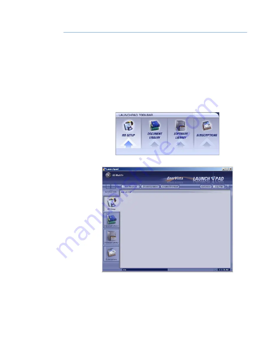
Click the 

IED Setup

 section of the LaunchPad toolbar.

5.

In the EnerVista Launchpad window, click the 

Add Product

 button near the top of the 

window..

Содержание Multilin DGT Series

Страница 1: ...venue Markham Ontario Canada L6E 1B3 Tel 905 294 6222 Fax 905 201 2098 Internet http www GEmultilin com Instruction manual DGT revision 1 0x Manual P N 1601 9045 A1 GE publication code GEK 113441 Copy...

Страница 2: ...A1 January 2008 FCC Part 15 Notice The equipment described in this manual complies with Part 15 of the FCC Rules Operation is subject to the following two conditions 1 this device may not cause harmf...

Страница 3: ...l installation 11 Dimensions 11 Installation Considerations 12 Mounting the enclosure 12 Electrical installation 14 Terminal identification 14 Terminal strip power connections 15 Terminal strip IO con...

Страница 4: ...CONTROL SYSTEM INSTRUCTION MANUAL TABLE OF CONTENTS 6 TROUBLESHOOTING Corrective action 49 Firmware updates 52 Updating the DGT R firmware 52 Updating the DGT U and DGT D firmware 52 7 DGT INTERCONNE...

Страница 5: ...lity at or near the Utility substation to coordinate wireless communication between the DGT U DGT R and the DGT D s DGT D is installed at the Distributed Generation site It receives the trip signal ov...

Страница 6: ...onitor the status of the auxiliary contact and transmit that status every 28 56 milliseconds back to the DGT U units constantly confirming current status All communication is coordinated through the D...

Страница 7: ...necessary input and output terminations antenna jumper cable and lightning protection contained in a weather resistant pad lockable enclosure The only connections required are for primary power the ex...

Страница 8: ...not shown for Connection from Lightning Arrestor to DGT U Transceiver Yagi Directional Antenna not shown Antenna Feedline not shown Figure 1 4 DGT R layout Components in the DGT R are A1 The DGT R Ra...

Страница 9: ...125 VDC Relay for Trip Status Confirmation Input Terminal blocks for external wiring connections 10 W self regulating internal heater A13 Bulkhead Lightning Arrestor with Connection for DGT D Antenna...

Страница 10: ...and 150 foot long antenna cable with connectors Standard features Each unit in the DGT Series comes with a number of standard features as shown below Table 1 Standard features DGT U Item Description D...

Страница 11: ...l battery or charger I O None LEDs 3 1 power 1 link 1 service Enclosure NEMA 4 Lightning arrester Nominal breakdown voltage 230V Field connection hardware Terminal blocks Item Description DGT D Contro...

Страница 12: ...Coil resistance 1400 Ohms maximum Power draw 400 mW Outputs specifications GENERAL Type Form A relay Service output is Form B Contact material silver alloy Operate time 10 ms Contact material Silver...

Страница 13: ...Cyclic IEC 60068 2 30 55 at 95 RH Surge Withstand Capability SWC Tests for Relay Systems Associated with Electrical Power Apparatus IEEE C37 90 1 2002 Standard for Withstand capability of Relay System...

Страница 14: ...1 10 DGT DISTRIBUTED GENERATION TRIP CONTROL SYSTEM INSTRUCTION MANUAL SPECIFICATIONS CHAPTER 1 INTRODUCTION...

Страница 15: ...ltilin Installation Mechanical installation This section describes the mechanical installation of the DGT system including dimensions for mounting Dimensions The dimensions of the DGT unit are shown b...

Страница 16: ...closely to the distance between the DGT U and the Utility s DGT R If that distance is limited for example up to 3 miles 4 8 km then some obstructions in the communications path can usually be tolerate...

Страница 17: ...ted to a wooden utility pole with two lag screws or with two long bolts that extend through the pole Threaded rod can also be used for through the pole mounting In either case it is important to use f...

Страница 18: ...ow more detailed views of power connections as required Route the power and I O signal wiring through the weathertight bushing on the bottom of the enclosure Do not tighten it until all cabling has be...

Страница 19: ...ION MANUAL 2 15 Terminal strip power connections Figure 2 5 DGT all models AC DC power connections refer to above terminal layouts Terminal strip IO connections Figure 2 6 DGT Terminal strip IO connec...

Страница 20: ...tput 4 5 DGT U DGT D Terminal Strip Contact Closure Customer Contact Closure 6 7 DGT D Terminal Strip Outputs Trip Output 8 Service Output Output Common 11 12 DGT U Terminal Strip Outputs Status 3 Out...

Страница 21: ...ease contact Multilin for information on arranging a Radio Path Analysis or Site Survey ANTENNA INSTALLATION DGT U and DGT D The antenna supplied with DGT D and DGT U units is a directional Yagi type...

Страница 22: ...the maximum EIRP from the antenna must not exceed 36 dBm Contact GE Multilin if assistance is required in determining the maximum output power setting SAFETY EARTH GROUNDING DGT equipment is equipped...

Страница 23: ...uts are in a failsafe state The input LED IN is illuminated whenever the trip status is energized The output LED OUT 1 illuminates whenever the associated output is energized OUT 1 will reflect the st...

Страница 24: ...adio configured for Slot 5 within the network If the output is in a failsafe state the LED shall flash a unique pattern to indicate this state The output LED OUT 6 illuminates whenever the associated...

Страница 25: ...s the state of the trip input on the DGT U within the network If the output is in a failsafe state the LED flashes a unique pattern to indicate this state If the output is configured and mapped to two...

Страница 26: ...NTERFACE PC requirements The following minimum requirements must be met for the EnerVista DGT Setup software to operate on your computer Pentium class processor 700 MHz or better recommended Microsoft...

Страница 27: ...PC DGT DISTRIBUTED GENERATION TRIP CONTROL SYSTEM INSTRUCTION MANUAL 3 23 Connecting to a PC Figure 3 1 Typical RS232 connection between PC and any DGT radio DGT U DGT R or DGT D RS232 CONNECTION ANY...

Страница 28: ...3 24 DGT DISTRIBUTED GENERATION TRIP CONTROL SYSTEM INSTRUCTION MANUAL CONNECTING TO A PC CHAPTER 3 USER INTERFACE...

Страница 29: ...above minimum requirements use the following procedure to install the EnerVista DGT DG Setup software from the enclosed GE EnerVista CD or the EnerVista website 1 Insert the GE EnerVista CD into your...

Страница 30: ...he EnerVista DGT DG used by the Distributed Generator can be loaded on a single computer 6 Select the EnerVista DGT DG Setup program as shown above Select the Web option to ensure you obtain the most...

Страница 31: ...te icons and add EnerVista DGT DG Setup software to the Windows start menu 10 Click Finish to end the installation The DGT device will be added to the list of installed IEDs in the EnerVista Launchpad...

Страница 32: ...er The main screen will appear as follows 3 Press the Quick Connect button near the top left edge of the screen The following window will appear 4 Using the dropdown box shown above select the COM por...

Страница 33: ...any attempt is made to send a Settings File to a unit whose serial number does not match in some way the following error message will be displayed A similar error message will be displayed if there i...

Страница 34: ...DGT system The status of the system is updated continuously every 5 seconds 11 To log out of EnerVista DGT DG Click on Logout Once you log out you have to press the Quick Connect button to log back i...

Страница 35: ...install the EnerVista DGT Utility Setup software from the enclosed GE EnerVista CD or the EnerVista web site 1 Insert the GE EnerVista CD into your CD ROM drive 2 Click the Install Now button and fol...

Страница 36: ...ista Launchpad will obtain the latest installation software from the Web or CD and automatically start the installation process A status window with a progress bar will be shown during the downloading...

Страница 37: ...units DGT U DGT U Recloser DGT R and DGT D 1 to 7 units allows the Utility to handle associated DGT information both on line and offline In the latter case information is uploaded to the specific DGT...

Страница 38: ...TY SETUP SOFTWARE CHAPTER 4 SOFTWARE 1 As indicated in the previous section open the DGT Utility Setup program 2 To define the framework of each DGT network click on File New System File The following...

Страница 39: ...cters are mandatory fields Unless you fill them in with some values the OK button will remain disabled so that it will not be possible to save your changes to the file Some other restrictions are appl...

Страница 40: ...must be checked as follows 6 Press OK and note that we have just created a new tree s brunch named Substation_1 which additionally contains the folder s name in which the created System file resides...

Страница 41: ...information NOTE NOTE The top two fields Name and Serial Number are mandatory and should be filled up in order to be able to store changes Only the content of these two fields can be uploaded to the d...

Страница 42: ...these two fields can be uploaded to the device The rest of the information should be considered as reference data for users only 9 Click on the sign on the DGT U node in the Offline window This will b...

Страница 43: ...oaded to the device The rest of the information should be considered as reference data for users only 12 After you press the OK button the System file tree will change as shown here NOTE NOTE Once you...

Страница 44: ...ppropriate devices DGT Utility configuration Creating and uploading a Settings File The Settings File is part of the whole DGT System configuration and is related to a dedicated device within the syst...

Страница 45: ...ity Setup program 2 In the Offline window find the System File you have just created 3 Now lets invesigate the content of the folder 4 As you can see there are two items the System File itself and an...

Страница 46: ...ite number 2 In our example we can easily see that file 3_1729024 hkf has been created for the device DGT D assigned to site 1 of DGT U Primary and its serial number is 1729024 NOTE NOTE If the user m...

Страница 47: ...the newly entered modified data to the appropriate Device s In this situation the term upload means to set the internal device s variables with the appropriate values specified in the System File For...

Страница 48: ...l connected DGT units will appear in the online window as shown below NOTE NOTE As we can see the type of the device is DGT U Primary and the serial number is 1729022 If we are going to upload an auto...

Страница 49: ...is to do this directly without using an intermediate Settings File In the Offline window you can select the desired device s node then select the Send to Online Device command from the context menu ri...

Страница 50: ...If you click on Status this window will appear The Status window continuously shows the synchronization state of the DGT system The status of the system is updated continuously every 5 seconds 16 To...

Страница 51: ...p When primary power is applied to the DGT U DGT R or DGT D the device is ready for configuration or if already configured for in service operation Once power is applied check for normal operation by...

Страница 52: ...6 1 for corrective actions DGT R Normal Operation The PWR Power LED is illuminated continuously when power is applied The LINK LED is illuminated continuously Note that the LED will blink when the DGT...

Страница 53: ...ON MANUAL 6 49 DGT Distributed Generation Trip Control System Chapter 6 Troubleshooting GE Consumer Industrial Multilin Troubleshooting Corrective action Please refer to the following tables for a sum...

Страница 54: ...LEDs on the DGT U should be flashing Note which OUT LED is flashing and check the appropriate DGT D for proper operation Note that if all OUT LEDs are flashing then communication with the DGT R could...

Страница 55: ...arm condition or Failsafe state Indicates that the DGT D has entered a failsafe state This means that communication with one or more DGT U devices has been lost The OUT 1 LED should also be flashing C...

Страница 56: ...IRMWARE UPDATES CHAPTER 6 TROUBLESHOOTING Firmware updates Updating the DGT R firmware Please contact GE Multilin for information on DGT R firmware updates Updating the DGT U and DGT D firmware Please...

Страница 57: ...1 A2 A1 A2 A1 A2 A1 A2 A1 A2 24 28 V 24 28 V OK 24 VDC 2 1A 24 VDC 2 1A L N 12 11 10 9 13 14 15 16 5 6 7 8 4 3 2 1 A1 NETio DG A2 POWER SUPPLY POWER SUPPLY TERMINAL BLOCKS A3 A4 A5 A6 A7 A10 A9 A8 REL...

Страница 58: ...L A 24 28 V 24 28 V OK 24 VDC 2 1A 24 VDC 2 1A L N COM2 PWR 6 30 VDC 2A max PWR 6 30 VDC 2A max LAN COM1 LINK PWR C CE SDP 2 24 100T SDP 2 24 100T Power Supply Power Supply S O L A S O L A 24 28 V 24...

Страница 59: ...list Part Number Description 03 4785A01 DGT U Radio Transceiver 03 4784A01 DGT R Radio Transceiver 03 4793A01 DGT D Radio Transceiver 29 4614A01 AC DC Fuse for DGT U DGT R and DGT D 31 1113A23 DPDT Re...

Страница 60: ...8 56 DGT DISTRIBUTED GENERATION TRIP CONTROL SYSTEM INSTRUCTION MANUAL CHAPTER 8 REPLACEMENT ASSEMBLIES...

Отзывы: