CHAPTER 4: THE DDFR AND RELAY INFORMATIONCONFIGURING THE EXTERNAL WATCHDOG
DISTRIBUTED DIGITAL FAULT RECORDER – INSTRUCTION MANUAL
79
The above settings screen shows a UR device configured to receive an External WatchDog
at VI 8 and a DriveSpace Watchdog at VI 9.
The Function setting must be enabled and the Type setting is set to Self-Reset.
The Virtual Input Name is changed to reflect the type of WatchDog being received.
The Events for VI 9 are enabled so that the DriveSpace event can be captured in the UR’s
Event Record. The Events for VI 8 are disabled because the External WatchDog command
is sent by the DDFR at a continuous interval with each command creating an entry in the
UR’s Event Record.
4.2.3.2 FlexLogic
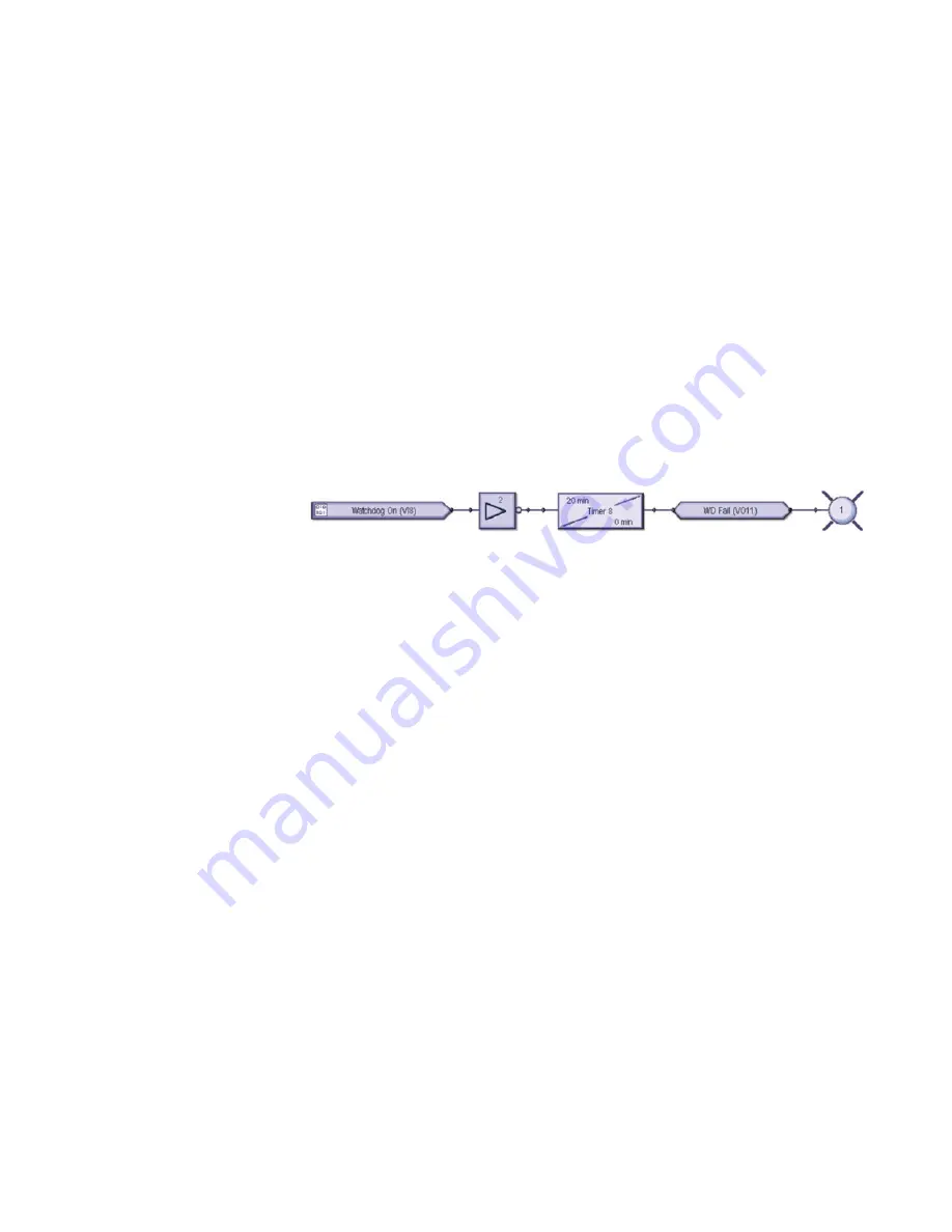
To complete the WatchDog logic, a FlexLogic equation needs to be created. An example of
the FlexLogic is shown in Figure 2-16. If the DDFR is configured to send an External
Watchdog every 10 minutes, then the timer is set for 20 minutes. When the timer
completes its countdown, logic should be triggered to indicate that the DDFR requires
attention; in this example it’s Virtual Output 11. This timer circuit will also restart the
countdown each time the Virtual Input command is received (VI 8).
FIGURE 4–11: FlexLogic equation (designed using Viewpoint Engineer 2.20)
In the above example, when the UR relay fails to receive the External WatchDog from the
DDFR, Virtual Output #11 will go high which will then turn ON User Programmable LED #1.
Содержание Multilin DDFR
Страница 3: ......
Страница 4: ......
Страница 8: ...TOC IV DISTRIBUTED DIGITAL FAULT RECORDER INSTRUCTION MANUAL TABLE OF CONTENTS ...
Страница 54: ...46 DISTRIBUTED DIGITAL FAULT RECORDER INSTRUCTION MANUAL SPECIFICATIONS CHAPTER 2 PRODUCT DESCRIPTION ...


