CHAPTER 5: POWERING UP THE D400
D400 SUBSTATION GATEWAY INSTRUCTION MANUAL
GE INFORMATION
83
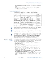
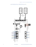
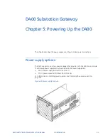
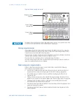
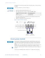
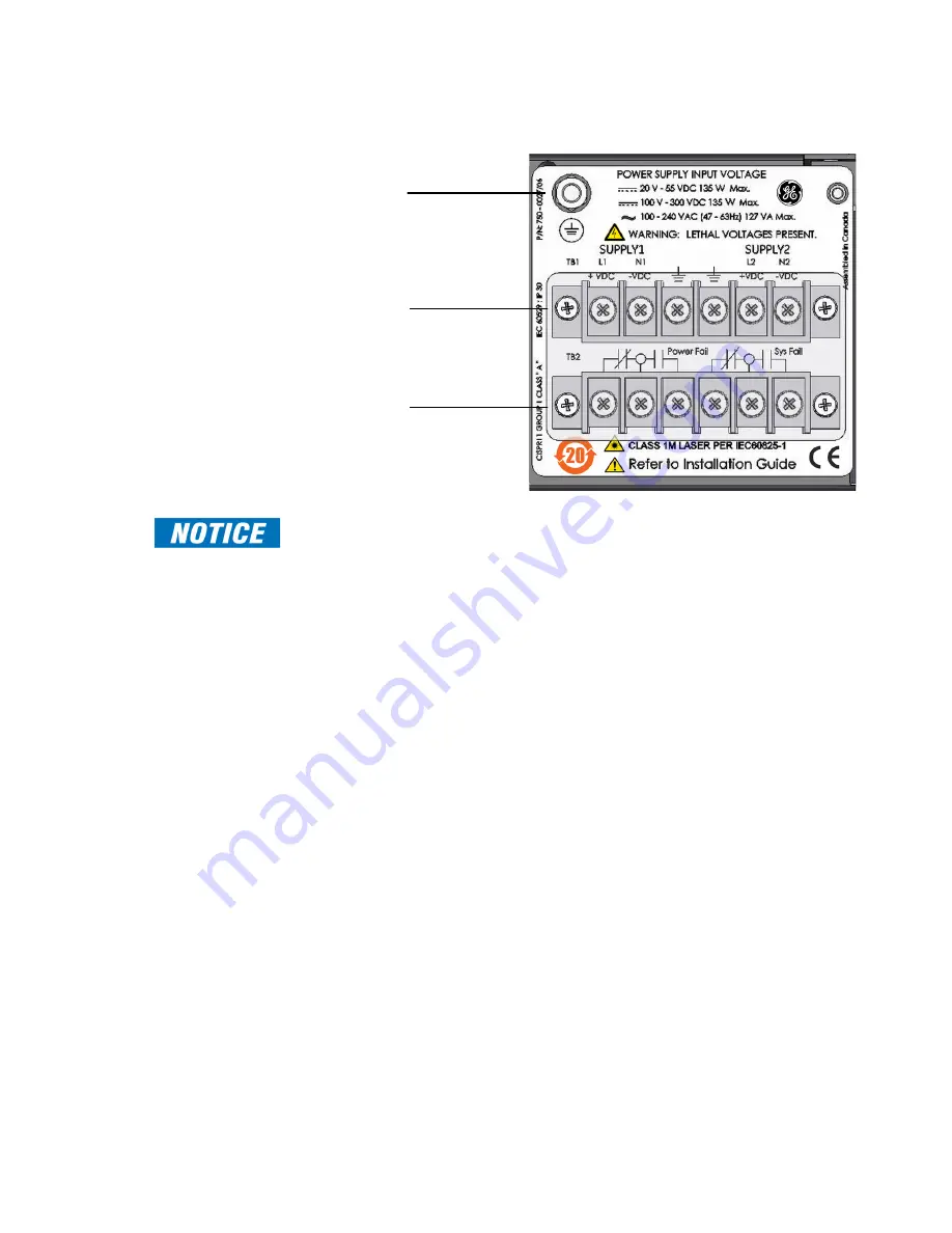
Figure 49: Power supply rear panel
The label on the power supply unit lists all possible power sources. Use only the source that
conforms to the specifications of the installed power supply type.
Wiring requirements
The supply wiring for the D400 must be a minimum of 18 AWG [0.82 mm²], 3-conductor
cable with an external insulation jacket, and a minimum certified voltage rating of 600 V.
Consult local and national electrical wiring codes.
The protective conductor must be minimum 16 AWG [1.3 mm²] wire with (green-&-yellow)
insulation. Recommended conductor size is 12 AWG [3.3 mm²].
The wires must be terminated with an insulated #6 Forked Terminal.
The clear plastic protective barrier provided with the terminal strip connector must be in
place once wiring of the mains is completed.
External power requirements
Before connecting an external power source to the D400, ensure that the following
external power requirements are met:
•
An IEC 61010 qualified primary disconnect device and over current protection not
exceeding 15 A must be externally provided in the AC/DC mains supply system.
•
All current carrying conductors must be switched, including neutral (for AC) and
negative (for DC).
•
Primary disconnect device must be rated for the proper voltages (AC and/or DC), as
well as inrush currents for the power supplies. See “Power supply options” on page 81
•
Protective earth conductor must be connected to the provided protective earth
terminal before any mains power conductors.
•
The primary disconnect device shall be in close proximity to the D400 equipment and
easily accessed by the operator.
•
The primary disconnect device shall be marked as the disconnecting device for the
D400 equipment.
Protective Earth
Terminal
Power Supply
Connections
Power Supply
Alarms
Содержание Multilin D400
Страница 12: ...12 GE INFORMATION D400 SUBSTATION GATEWAY INSTRUCTION MANUAL PRODUCT SUPPORT ...
Страница 28: ...28 GE INFORMATION D400 SUBSTATION GATEWAY INSTRUCTION MANUAL CHAPTER 1 BEFORE YOU START ...
Страница 34: ...34 GE INFORMATION D400 SUBSTATION GATEWAY INSTRUCTION MANUAL CHAPTER 2 INSTALLING THE D400 ...
Страница 80: ...80 GE INFORMATION D400 SUBSTATION GATEWAY INSTRUCTION MANUAL CHAPTER 4 CONNECTING TO DEVICES AND NETWORKS ...
Страница 88: ...88 GE INFORMATION D400 SUBSTATION GATEWAY INSTRUCTION MANUAL CHAPTER 5 POWERING UP THE D400 ...
Страница 104: ...104 GE INFORMATION D400 SUBSTATION GATEWAY INSTRUCTION MANUAL CHAPTER 7 SETTING UP THE D400 FOR REDUNDANCY ...
Страница 118: ...118 GE INFORMATION D400 SUBSTATION GATEWAY INSTRUCTION MANUAL CHAPTER 9 ABOUT THE D400 APPLICATIONS ...
Страница 126: ...126 GE INFORMATION D400 SUBSTATION GATEWAY INSTRUCTION MANUAL CHAPTER 10 INTRODUCING THE D400 CONFIGURATION ...
Страница 158: ...158 GE INFORMATION D400 SUBSTATION GATEWAY INSTRUCTION MANUAL CHAPTER 12 USING THE D400 LOCAL CONFIGURATION UTILITY ...
Страница 174: ...174 GE INFORMATION D400 SUBSTATION GATEWAY INSTRUCTION MANUAL APPENDIX A STANDARDS PROTECTION ...
Страница 184: ...184 GE INFORMATION D400 SUBSTATION GATEWAY INSTRUCTION MANUAL APPENDIX C LIST OF ACRONYMS ...
Страница 192: ...192 GE INFORMATION D400 SUBSTATION GATEWAY INSTRUCTION MANUAL INDEX ...

