74
GE INFORMATION
D400 SUBSTATION GATEWAY INSTRUCTION MANUAL
CHAPTER 4: CONNECTING TO DEVICES AND NETWORKS
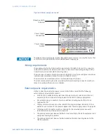
To manually operate
the RS232 switch
panel:
1.
Pull the active/standby switch straight out to release it from the locked position
2.
Switch it up to make unit A active or down to make unit B active
The CCU A/CCU B LED indicator indicates which unit has been activated.
Redundancy wiring diagrams
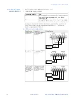
The following diagrams illustrate how to wire the D400 units and RS232 switch panels to
enable system redundancy:
•
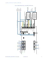
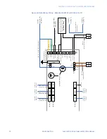
Redundancy Wiring - Single RS232 Switch Panel
See “Redundancy Wiring - Single RS232 Switch Panel” on page 75.
•
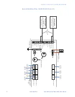
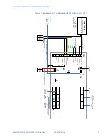
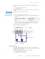
Redundancy Wiring - Dual RS232 Switch Panel. The wiring drawing is provided in two
parts: left and right.
–
For the left side of the drawing, see “Redundancy Wiring - Dual RS232 Switch
Panel (1 of 2)” on page 76
–
For the right side of the drawing, see “Redundancy Wiring - Dual RS232 Switch
Panel (2 of 2)” on page 77
This configuration is used to provide up to 15 serial connections to the redundant
D400 units.
•
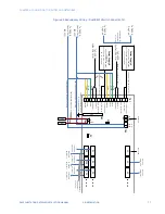
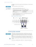
Redundancy Wiring - Redundant RS232 Switch Panel. The wiring drawing is provided
in two parts: left and right.
–
For the left side of the drawing, see “Redundancy Wiring - Redundant RS232
Switch Panel (1 of 2)” on page 78
–
For the left side of the drawing, see “Redundancy Wiring - Redundant RS232
Switch Panel (2 of 2)” on page 79
This configuration is used to provide RS232 panel redundancy for up to 7 serial
connections.
NOTE
When connecting to more than 7 field devices, you must double the number of RS232
switch panels used. When using this configuration, follow the instructions in “To set up a
redundant system with two RS232 switch panels:” on page 73.
NOTE
The D400 watchdog (control) port, heartbeat (ping) port, and serial port assignments are
software configurable. Refer to section: “D400 system redundancy” on page 71.
Содержание Multilin D400
Страница 12: ...12 GE INFORMATION D400 SUBSTATION GATEWAY INSTRUCTION MANUAL PRODUCT SUPPORT ...
Страница 28: ...28 GE INFORMATION D400 SUBSTATION GATEWAY INSTRUCTION MANUAL CHAPTER 1 BEFORE YOU START ...
Страница 34: ...34 GE INFORMATION D400 SUBSTATION GATEWAY INSTRUCTION MANUAL CHAPTER 2 INSTALLING THE D400 ...
Страница 80: ...80 GE INFORMATION D400 SUBSTATION GATEWAY INSTRUCTION MANUAL CHAPTER 4 CONNECTING TO DEVICES AND NETWORKS ...
Страница 88: ...88 GE INFORMATION D400 SUBSTATION GATEWAY INSTRUCTION MANUAL CHAPTER 5 POWERING UP THE D400 ...
Страница 104: ...104 GE INFORMATION D400 SUBSTATION GATEWAY INSTRUCTION MANUAL CHAPTER 7 SETTING UP THE D400 FOR REDUNDANCY ...
Страница 118: ...118 GE INFORMATION D400 SUBSTATION GATEWAY INSTRUCTION MANUAL CHAPTER 9 ABOUT THE D400 APPLICATIONS ...
Страница 126: ...126 GE INFORMATION D400 SUBSTATION GATEWAY INSTRUCTION MANUAL CHAPTER 10 INTRODUCING THE D400 CONFIGURATION ...
Страница 158: ...158 GE INFORMATION D400 SUBSTATION GATEWAY INSTRUCTION MANUAL CHAPTER 12 USING THE D400 LOCAL CONFIGURATION UTILITY ...
Страница 174: ...174 GE INFORMATION D400 SUBSTATION GATEWAY INSTRUCTION MANUAL APPENDIX A STANDARDS PROTECTION ...
Страница 184: ...184 GE INFORMATION D400 SUBSTATION GATEWAY INSTRUCTION MANUAL APPENDIX C LIST OF ACRONYMS ...
Страница 192: ...192 GE INFORMATION D400 SUBSTATION GATEWAY INSTRUCTION MANUAL INDEX ...

