


CHAPTER 4: CONNECTING TO DEVICES AND NETWORKS
D400 SUBSTATION GATEWAY INSTRUCTION MANUAL
GE INFORMATION
73
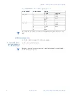
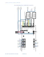
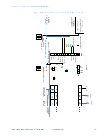
7.
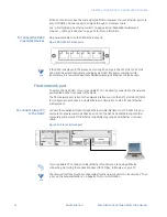
Use standard RS232 cables (GE part number 977-0145) to connect the D400 serial
communication ports to the serial ports on the RS232 switch panel. P2 through P8 are
connected to the first D400, P10 through P16 are connected to the second D400.
Connections from the switch panel to both D400 units should be made in the same
order. For example, if P2 is connected to port 3 on the first D400, P10 should also be
connected to port 3 on the second D400.
8.
Connect field devices to J2 through J8 on the RS232 switch panel.
9.
Configure the software. See section: “D400 system redundancy” on page 71.
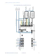
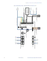
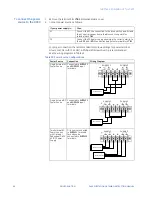
To set up a redundant
system with two
RS232 switch panels:
In cases where more than 7 serial connection ports are required, a second RS232 panel
can be added to the redundancy setup.
1.
Mount the D400 units in a rack and connect power and ground. See section “Power
connections” on page 82.
2.
Mount the two RS232 switch panels.
3.
Plug the connector of watchdog cable A (GE part number 977-0540) to a serial
connector on the first D400 (CCU A).
4.
Plug the connector of watchdog cable B (GE part number 977-0541) to a serial
connector on the second D400 (CCU B). This cable must be connected to the same
serial port number on both units.
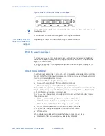
5.
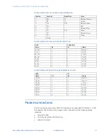
Connect the bare leads of both watchdog cables to TB1 on the master RS232 switch
panel as shown below.
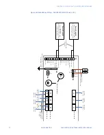
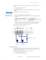
6.
Connect TB4 pins 1 (SET) and 2 (RESET) on the master RS232 switch panel to TB2 pins 1
and 2 on the slave RS232 switch panel using the cable specified (GE part number 970-
0161) or similar.
7.
Remove jumpers Z1 and Z2 from the slave RS232 switch panel.
8.
Connect one end of the ping cable to the first D400 and the other end to the second
D400. This ping cable must be connected to the same serial port number on both
units.
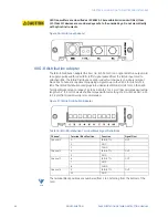
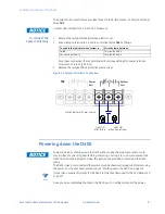
9.
Use standard RS232 cables (GE part number 977-0145) to connect the D400 serial
communication ports to the serial ports on the RS232 switch panels. P2 through P8
are connected to the first D400, P10 through P16 are connected to the second D400.
Connections from the switch panel to both D400 units should be made in the same
order. For example, if P2 is connected to port 3 on the first D400, P10 should also be
connected to port 3 on the second D400.
10. Connect field devices to J2 through J8 on the first RS232 switch panel and to J1
through J8 on the second panel.
11. Configure the software. See section: “D400 system redundancy” on page 71.
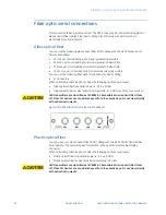
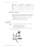
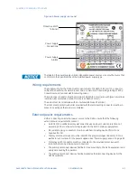
RS232 switch panel
The RS232 switch panel has two sets of indicator LEDS:
•
PWR A/PWR B: When lit, power and communications are received from the connected
units. Normally, both LEDs are lit.
•
CCU A/CCU B: Normally, one LED is lit, indicating which unit is active.
The active/standby switch on the front of the RS232 switch panel is used to:
•
Restore a previously failed unit to active status once it has been repaired.
•
Manually force a unit to active status so that routine maintenance can be performed
on the other unit.
Содержание Multilin D400
Страница 12: ...12 GE INFORMATION D400 SUBSTATION GATEWAY INSTRUCTION MANUAL PRODUCT SUPPORT ...
Страница 28: ...28 GE INFORMATION D400 SUBSTATION GATEWAY INSTRUCTION MANUAL CHAPTER 1 BEFORE YOU START ...
Страница 34: ...34 GE INFORMATION D400 SUBSTATION GATEWAY INSTRUCTION MANUAL CHAPTER 2 INSTALLING THE D400 ...
Страница 80: ...80 GE INFORMATION D400 SUBSTATION GATEWAY INSTRUCTION MANUAL CHAPTER 4 CONNECTING TO DEVICES AND NETWORKS ...
Страница 88: ...88 GE INFORMATION D400 SUBSTATION GATEWAY INSTRUCTION MANUAL CHAPTER 5 POWERING UP THE D400 ...
Страница 104: ...104 GE INFORMATION D400 SUBSTATION GATEWAY INSTRUCTION MANUAL CHAPTER 7 SETTING UP THE D400 FOR REDUNDANCY ...
Страница 118: ...118 GE INFORMATION D400 SUBSTATION GATEWAY INSTRUCTION MANUAL CHAPTER 9 ABOUT THE D400 APPLICATIONS ...
Страница 126: ...126 GE INFORMATION D400 SUBSTATION GATEWAY INSTRUCTION MANUAL CHAPTER 10 INTRODUCING THE D400 CONFIGURATION ...
Страница 158: ...158 GE INFORMATION D400 SUBSTATION GATEWAY INSTRUCTION MANUAL CHAPTER 12 USING THE D400 LOCAL CONFIGURATION UTILITY ...
Страница 174: ...174 GE INFORMATION D400 SUBSTATION GATEWAY INSTRUCTION MANUAL APPENDIX A STANDARDS PROTECTION ...
Страница 184: ...184 GE INFORMATION D400 SUBSTATION GATEWAY INSTRUCTION MANUAL APPENDIX C LIST OF ACRONYMS ...
Страница 192: ...192 GE INFORMATION D400 SUBSTATION GATEWAY INSTRUCTION MANUAL INDEX ...


