CHAPTER 4: CONNECTING TO DEVICES AND NETWORKS
D400 SUBSTATION GATEWAY INSTRUCTION MANUAL
GE INFORMATION
63
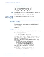
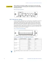
Figure 35: D400 Plastic Optical Fiber Serial adapter
NOTE
It is possible to saturate the receiver input if the cable used is too short. Inline attenuation
may be required.
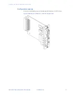
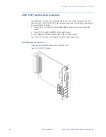
See “Fiber optic serial adapter” on page 43 for configuration options.
To connect fiber optic
links to the Fiber Optic
adapters
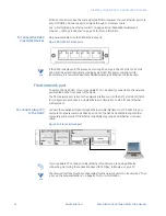
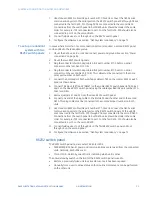
Plug fiber optic cables into the corresponding TX and RX connectors.
IRIG-B connections
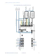
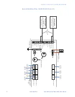
The D400 uses a pair of IRIG-B adapter cards, the IRIG-B Input Adapter and the IRIG-B
Distribution Adapter, to accept an IRIG-B signal from a GPS receiver then distribute the
signal to connected IEDs.
See “IRIG-B input adapter” on page 44 and “IRIG-B distribution adapter” on page 47 for
more information.
IRIG-B input adapter
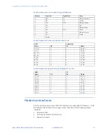
The IRIG-B Input Adapter (GE Item No. 520-0211LF) plugs into a dedicated IRIG-B slot (slot
9) on the D400. The IRIG-B Input card accepts an IRIG-B signal in one of three input formats
through a corresponding connector type:
•
Modulated IRIG-B through a BNC connector
•
Pulse width coded IRIG-B (
TTL
) through a terminal block
•
Fiber Optic through a Receive (
RX
) 820-850 nm ST connector
Terminal blocks accept a range of 24 to 14 AWG [0.2 to 2.1 mm²] Recommended wire strip
length is 0.2" [5.0 mm]. Screws shall be torqued with tool setting of 4.2 in-lb [0.46 Nm]. A 3.0
to 3.5 mm flat screwdriver tip is recommended.
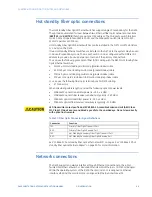
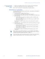
You can use the following glass optical fiber (GOF) cabling with the D400 Glass Optical
Fiber Serial adapter:
•
50/125 µm core/cladding multi-mode (gradient index) cable
•
62.5/125 µm core cladding multi-mode (gradient index) cable
•
100/140 µm core/cladding multi-mode (gradient index) cable
•
200 m core Hard-Clad Silica (HCS) multi-mode (step index) cable
You can use the following fiber optic terminations for D400 cabling:
•
ST Connectors
When calculating cable length, consider the following optical power levels:
•
Glass optical fiber receiver sensitivity is typically –25.4 dBm
Содержание Multilin D400
Страница 12: ...12 GE INFORMATION D400 SUBSTATION GATEWAY INSTRUCTION MANUAL PRODUCT SUPPORT ...
Страница 28: ...28 GE INFORMATION D400 SUBSTATION GATEWAY INSTRUCTION MANUAL CHAPTER 1 BEFORE YOU START ...
Страница 34: ...34 GE INFORMATION D400 SUBSTATION GATEWAY INSTRUCTION MANUAL CHAPTER 2 INSTALLING THE D400 ...
Страница 80: ...80 GE INFORMATION D400 SUBSTATION GATEWAY INSTRUCTION MANUAL CHAPTER 4 CONNECTING TO DEVICES AND NETWORKS ...
Страница 88: ...88 GE INFORMATION D400 SUBSTATION GATEWAY INSTRUCTION MANUAL CHAPTER 5 POWERING UP THE D400 ...
Страница 104: ...104 GE INFORMATION D400 SUBSTATION GATEWAY INSTRUCTION MANUAL CHAPTER 7 SETTING UP THE D400 FOR REDUNDANCY ...
Страница 118: ...118 GE INFORMATION D400 SUBSTATION GATEWAY INSTRUCTION MANUAL CHAPTER 9 ABOUT THE D400 APPLICATIONS ...
Страница 126: ...126 GE INFORMATION D400 SUBSTATION GATEWAY INSTRUCTION MANUAL CHAPTER 10 INTRODUCING THE D400 CONFIGURATION ...
Страница 158: ...158 GE INFORMATION D400 SUBSTATION GATEWAY INSTRUCTION MANUAL CHAPTER 12 USING THE D400 LOCAL CONFIGURATION UTILITY ...
Страница 174: ...174 GE INFORMATION D400 SUBSTATION GATEWAY INSTRUCTION MANUAL APPENDIX A STANDARDS PROTECTION ...
Страница 184: ...184 GE INFORMATION D400 SUBSTATION GATEWAY INSTRUCTION MANUAL APPENDIX C LIST OF ACRONYMS ...
Страница 192: ...192 GE INFORMATION D400 SUBSTATION GATEWAY INSTRUCTION MANUAL INDEX ...


