176
GE INFORMATION D400 SUBSTATION GATEWAY INSTRUCTION MANUAL
APPENDIX B INSTALLING AND CONNECTING DNP3 I/O MODULES
Installing DNP3 I/O modules in a rack
Rack spacing
When mounting multiple DNP3 I/O modules in a rack, or when mounting DNP3 I/O
modules in a rack with other equipment, verify that there is at least one rack unit (RU) of
space above and below the DNP03 I/O module to allow for cooling air flow and cable
routing (1 RU = 1.75 inches or 44.5 mm).
Required clearances
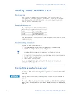
The exterior dimensions of the DNP3 I/O module are:
Allow about 14 inches (356 mm) of total cabinet depth, to provide clearance for cables and
maintenance access.
Rack mounting procedure
To mount the DNP3 I/O module in a rack:
1.
Determine the location of the DNP3 I/O module in a 19-inch mounting rack.
2.
Install, but do not tighten the top two mounting screws.
NOTE
Install the DNP3 I/O module with the LEDs visible from the front of the rack.
3.
Slide the DNP3 I/O module over the top mounting screws and drop down into position.
4.
Insert the bottom mounting screws.
5.
Tighten all four mounting screws.
You are now ready to connect ground to the DNP I/O module. See “Connecting to
protective ground” on page 176.
Connecting to protective ground
Connect your DNP3 I/O module to site ground, using a separate 2.05 mm (12 AWG) Yellow/
Green wire.
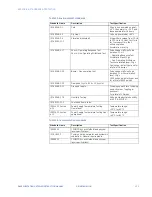
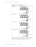
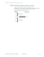
Each type of DNP I/O Module has a different ground point, as shown in the examples of
Table 57.
The location of the protective ground terminal varies between WESTERM I/O module types.
Refer to Module Layout drawing of your module for detailed information. For example, see
Table 57.
Dimension
Measurement
Width
19 inches (
483 mm)
Height
5.25 inches (
133.4 mm)
Depth
2.5
inches (63.5 mm)
Содержание Multilin D400
Страница 12: ...12 GE INFORMATION D400 SUBSTATION GATEWAY INSTRUCTION MANUAL PRODUCT SUPPORT ...
Страница 28: ...28 GE INFORMATION D400 SUBSTATION GATEWAY INSTRUCTION MANUAL CHAPTER 1 BEFORE YOU START ...
Страница 34: ...34 GE INFORMATION D400 SUBSTATION GATEWAY INSTRUCTION MANUAL CHAPTER 2 INSTALLING THE D400 ...
Страница 80: ...80 GE INFORMATION D400 SUBSTATION GATEWAY INSTRUCTION MANUAL CHAPTER 4 CONNECTING TO DEVICES AND NETWORKS ...
Страница 88: ...88 GE INFORMATION D400 SUBSTATION GATEWAY INSTRUCTION MANUAL CHAPTER 5 POWERING UP THE D400 ...
Страница 104: ...104 GE INFORMATION D400 SUBSTATION GATEWAY INSTRUCTION MANUAL CHAPTER 7 SETTING UP THE D400 FOR REDUNDANCY ...
Страница 118: ...118 GE INFORMATION D400 SUBSTATION GATEWAY INSTRUCTION MANUAL CHAPTER 9 ABOUT THE D400 APPLICATIONS ...
Страница 126: ...126 GE INFORMATION D400 SUBSTATION GATEWAY INSTRUCTION MANUAL CHAPTER 10 INTRODUCING THE D400 CONFIGURATION ...
Страница 158: ...158 GE INFORMATION D400 SUBSTATION GATEWAY INSTRUCTION MANUAL CHAPTER 12 USING THE D400 LOCAL CONFIGURATION UTILITY ...
Страница 174: ...174 GE INFORMATION D400 SUBSTATION GATEWAY INSTRUCTION MANUAL APPENDIX A STANDARDS PROTECTION ...
Страница 184: ...184 GE INFORMATION D400 SUBSTATION GATEWAY INSTRUCTION MANUAL APPENDIX C LIST OF ACRONYMS ...
Страница 192: ...192 GE INFORMATION D400 SUBSTATION GATEWAY INSTRUCTION MANUAL INDEX ...

