6–88
850 FEEDER PROTECTION SYSTEM – INSTRUCTION MANUAL
VOLTAGE ELEMENTS
CHAPTER 6: PROTECTION SETPOINTS
Timed Undervoltage Protection (27T)
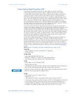
The 850 relay provides one Timed Phase Undervoltage (UV) protection element per
protection group. This element may be used for protection against transient voltage drops
and low voltage ride through applications.
In certain regions of the world, the power plants must meet certain requirements of grid
support. In case of a voltage drop, the power plants are sometimes required to continue
supporting the grid and not be disconnected from the grid. Therefore, a conventional
phase undervoltage protection may not be adequate for such scenarios. The Timed
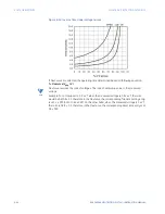
Undervoltage element can be set as a time dependent element which can be programmed
with ten configurable points that make up its characteristics curve. The configurable curve
allows the relay to continue the grid support for brief voltage drops and operate for
voltage drops that enter the operate region of the configurable curve. Additionally, the
element provides a counter based protection which counts the number of transient
voltage drops and trips according to the provided threshold for the given time window. This
counter based logic is functional only if the overall element is enabled. The counter mode
can be enabled/disabled and it runs in parallel to the configurable characteristics based
protection. The Timed Undervoltage element has programmable minimum operating
threshold to prevent some undesired operation when voltage is not available. The input
voltages are the three phase to phase voltages from delta connected VTs (PTs) or three
phase to ground voltages from wye connected VTs (PTs).
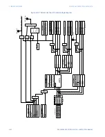
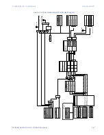
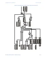
The settings of this function are applied to each of the three voltage inputs to produce
pickup and trip flags per voltage input. The UV pickup flag is asserted, when the measured
voltage on any of the three voltage inputs is below the PKP value and deserted when it
reaches above the dropout level. The Timed UV 1 Trip flag is asserted if the element stays
picked up for the time defined by curve, and number of voltages required for operation
matches the number of voltages selected in the setting.The minimum voltage setting
selects the operating voltage below which the element is blocked.
Path
:
Setpoints > Protection > Group 1(6) > Voltage Elements > Timed UV 1(X)
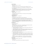
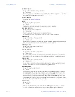
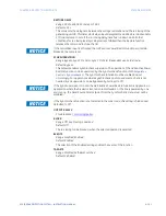
FUNCTION
Range: Disabled, Trip, Alarm, Latched Alarm, Configurable
Default: Disabled
SIGNAL INPUT
Range: dependant upon the order code
Default: Ph VT Bnk1-J2 or LEA Bnk1-J2 (order code dependant)
This setting provides the phase VTs input selection.
MODE
Range: Phase to Ground, Phase to Phase
Default: Phase to Ground
This setting provides the selection of phase to ground and phase to phase voltages for a
Wye VT connection (phase to phase for delta connected VT connection).
FASTPATH:
Only Phase to Phase mode shall be selected when Delta is programmed for the Phase VT
Connection setting under System/Voltage Sensing.
PHASES FOR OPERATION
Range: Any One, Any Two, All Three
Default: Any One
This setting defines the number of voltages required for operation of the Timed UV
protection function.
Содержание Multilin 850
Страница 10: ...VIII 850 FEEDER PROTECTION SYSTEM INSTRUCTION MANUAL ...
Страница 135: ...CHAPTER 3 INTERFACES SOFTWARE INTERFACE 850 FEEDER PROTECTION SYSTEM INSTRUCTION MANUAL 3 41 ...
Страница 151: ...CHAPTER 3 INTERFACES SOFTWARE INTERFACE 850 FEEDER PROTECTION SYSTEM INSTRUCTION MANUAL 3 57 ...
Страница 153: ...CHAPTER 3 INTERFACES SOFTWARE INTERFACE 850 FEEDER PROTECTION SYSTEM INSTRUCTION MANUAL 3 59 ...
Страница 268: ...5 106 850 FEEDER PROTECTION SYSTEM INSTRUCTION MANUAL OUTPUTS CHAPTER 5 DEVICE SYSTEM INPUT AND OUTPUT SETPOINTS ...
Страница 420: ...6 152 850 FEEDER PROTECTION SYSTEM INSTRUCTION MANUAL FREQUENCY ELEMENTS CHAPTER 6 PROTECTION SETPOINTS ...
Страница 439: ...CHAPTER 7 MONITORING FUNCTIONS 850 FEEDER PROTECTION SYSTEM INSTRUCTION MANUAL 7 19 ...
Страница 644: ...11 20 850 FEEDER PROTECTION SYSTEM INSTRUCTION MANUAL FLEXELEMENTS CHAPTER 11 METERING ...


