


3–16
489 GENERATOR MANAGEMENT RELAY – INSTRUCTION MANUAL
CHAPTER 3: INSTALLATION
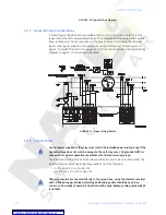
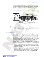
The 489 RTD circuitry compensates for lead resistance, provided that each of the three
leads is the same length. Lead resistance should not exceed 25
Ω
per lead for platinum
and nickel RTDs and 3
Ω
per lead for copper RTDs. Shielded cable should be used to
prevent noise pickup in the industrial environment. RTD cables should be kept close to
grounded metal casings and avoid areas of high electromagnetic or radio interference.
RTD leads should not be run adjacent to or in the same conduit as high current carrying
wires.
FIGURE 3–17: RTD Wiring
Note
IMPORTANT NOTE
: The RTD circuitry is isolated as a group with the Analog Input circuitry
and the Analog Output circuitry. Only one ground reference should be used for the three
circuits. Transorbs limit this isolation to ±36 V with respect to the 489 safety ground. If code
requires that the RTDs be grounded locally at the generator terminal box, that will also be
the ground reference for the analog inputs and outputs.
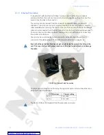
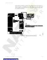
3.2.10 Output Relays
There are six Form-C output relays (see
on page 2–7). Five of the six relays are
always non-failsafe, the 6 Service relay is always failsafe. As a failsafe, the 6 Service relay
will be energized normally and de-energize when called upon to operate. It will also de-
energize when control power to the 489 is lost and therefore, be in its operated state. All
other relays, being non-failsafe, will be de-energized normally and energize when called
upon to operate. Obviously, when control power is lost to the 489, these relays must be de-
energized and therefore, they will be in their non-operated state. Shorting bars in the
drawout case ensure that when the 489 is drawn out, no trip or alarm occurs. The
6 Service output will however indicate that the 489 has been drawn out. Each output relay
has an LED indicator on the 489 front panel that comes on while the associated relay is in
the operated state.
•
1 TRIP
: The trip relay should be wired such that the generator is taken offline when
conditions warrant. For a breaker application, the NO 1 Trip contact should be wired in
series with the Breaker trip coil.
Supervision of a breaker trip coil requires that the supervision circuit be paralleled with
the 1 Trip relay output contacts, as shown in the
With this connection made, the supervision input circuits will place an impedance
across the contacts that will draw a current of 2 to 5 mA (for an external supply
3 WIRE SHIELDED CABLE
RTD
TERMINALS
RTD TERMINALS
AT GENERATOR
Maximum total lead resistance
25 ohms (Platinum & Nickel RTDs)
3 ohms (Copper RTDs)
OPTIONAL GROUND
Shield is internally
connected to safety
ground terminal G12
Route cable in separate conduit from
current carrying conductors
RTD IN
GENERATOR
STATOR
OR
BEARING
808761E4.CDR
B1
A1
A2
A3
HOT
COMPENSATION
RETURN
SHIELD
CHASSIS
GROUND
R
T
D
SENSING
RT
D
#
1
489
RELAY
Содержание Multilin 489
Страница 3: ...Courtesy of NationalSwitchgear com ...
Страница 4: ...Courtesy of NationalSwitchgear com ...
Страница 110: ...4 48 489 GENERATOR MANAGEMENT RELAY INSTRUCTION MANUAL CHAPTER 4 INTERFACES Courtesy of NationalSwitchgear com ...
Страница 272: ...7 22 489 GENERATOR MANAGEMENT RELAY INSTRUCTION MANUAL CHAPTER 7 TESTING Courtesy of NationalSwitchgear com ...


