CHAPTER 4: INTERFACES
FRONT PANEL INTERFACE
M60 MOTOR PROTECTION SYSTEM – INSTRUCTION MANUAL
4-39
4
The
ENTER
key stores setting values.
When entering an IP address on the front panel, key in the first sequence of the number, then press the • key for the
decimal place. For example, for 127.0.0.1, press 127, then •, then 0, then •, then 0, then •, then 1. To save the address, press
the
ENTER
key.
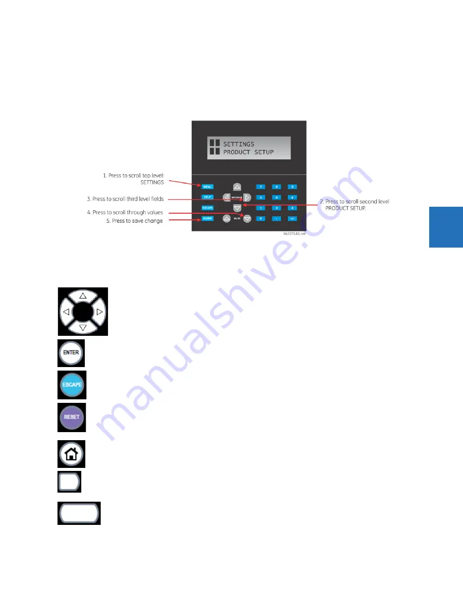
The figure shows the sequence to use to enter a setting. Subsequent sections provide more detail.
Figure 4-46: Front panel keypad use (standard front panel shown)
4.2.3.2 Graphical front panel
These keys and pushbuttons navigate and select items.
Up/Down/Left/Right
— These pushbuttons move the selector among the options on a page. The selection is
indicated by a yellow background or a yellow border. On menu pages, the Right pushbutton activates the selected
submenu drilling down the menu hierarchy, and the Left pushbutton backs up the menu hierarchy. These
pushbuttons have a typematic feature on some pages: after a short pause, the pushbutton repeats as long as it is
pressed.
ENTER
— Activates the selection on the display, for example a submenu, a control, a keypad key, or a setting. Also
stores updated settings.
ESCAPE
— If a setting is open for edit, this pushbutton closes the setting without saving. If a popup menu is open,
this pushbutton closes it. If an item is selected, this pushbutton deselects it. Otherwise this pushbutton activates
the previous page in the page hierarchy.
RESET
— Clears all latched LED indications and target messages. When a page with acknowledgeable/resettable
items is displayed, it instead resets/acknowledges all items on that page, or if an item on that page is selected, it
resets/acknowledges that item.
If you reset/acknowledge alarms, they stop flashing but remain in the alarm state as long as that state remains. In
other words, a red alarm does not switch off just because you acknowledged the alarm.
Home
— Activates the home page, which is the root page. The page displays product information by default and
is configurable.
Side pushbutton
— Five pushbuttons on the left side of the display and five pushbuttons on the right side of the
display. They perform various functions depending on the displayed page, such as switchgear controls. The
display dynamically shows its label next to each side pushbutton when the pushbutton has an assigned function.
These pushbuttons can also be programmed to function as user-programmable pushbuttons 9 to 16.
Tab pushbutton
— Five pushbuttons under the display. They navigate through the page hierarchy, and on some
pages activate other actions. The display footer dynamically labels the page or action that is activated by the tab
pushbutton.
Содержание M60
Страница 9: ...TABLE OF CONTENTS M60 MOTOR PROTECTION SYSTEM INSTRUCTION MANUAL ix INDEX ...
Страница 10: ...x M60 MOTOR PROTECTION SYSTEM INSTRUCTION MANUAL TABLE OF CONTENTS ...
Страница 14: ...1 4 M60 MOTOR PROTECTION SYSTEM INSTRUCTION MANUAL FOR FURTHER ASSISTANCE CHAPTER 1 INTRODUCTION 1 ...
Страница 208: ...4 88 M60 MOTOR PROTECTION SYSTEM INSTRUCTION MANUAL FLEXLOGIC DESIGN USING ENGINEER CHAPTER 4 INTERFACES 4 ...
Страница 494: ...5 286 M60 MOTOR PROTECTION SYSTEM INSTRUCTION MANUAL CONTROL ELEMENTS CHAPTER 5 SETTINGS 5 Figure 5 158 Time out mode ...
Страница 552: ...5 344 M60 MOTOR PROTECTION SYSTEM INSTRUCTION MANUAL TESTING CHAPTER 5 SETTINGS 5 ...
Страница 596: ...7 14 M60 MOTOR PROTECTION SYSTEM INSTRUCTION MANUAL TARGETS MENU CHAPTER 7 COMMANDS AND TARGETS 7 ...
Страница 602: ...9 4 M60 MOTOR PROTECTION SYSTEM INSTRUCTION MANUAL SATURATION DETECTOR CHAPTER 9 THEORY OF OPERATION 9 ...
Страница 652: ...C 6 M60 MOTOR PROTECTION SYSTEM INSTRUCTION MANUAL COMMAND LINE INTERFACE APPENDIX C COMMAND LINE INTERFACE C ...
Страница 660: ...iv M60 MOTOR PROTECTION SYSTEM INSTRUCTION MANUAL ABBREVIATIONS ...


