CHAPTER 5: COMMUNICATIONS
DEVICENET OPERATIONS
LM10 MOTOR PROTECTION SYSTEM – INSTRUCTION MANUAL
5–57
5.1.11 Data Formats
F1: Full Load Current (16-bit unsigned integer)
Range: 0x000C to 0x1F40 (i.e. 1.2 to 800.0 A)
Multiplying factor: 0.1
Example: 123.4 stored as 1234
F2: Ground Fault
Format: two bytes in format 0xHHLL, where LL is the pickup level and HH is the time delay
Byte LL range: 0x00, 0x02 to 0x64 (i.e. 0.4 to 20.0 A), where 0x00 is disabled
Byte LL multiplying factor: 0.2 (i.e. actual = byte LL in decimal
×
0.2 amps)
Byte HH range: 0x00 to 0x19 (i.e. 0 to 2.5 seconds)
Byte HH multiplying factor: 0.1 (i.e. actual = byte HH in decimal
×
0.1 seconds)
F3: Jam
Format: two bytes in format 0xHHLL, where LL is the pickup level and HH is the time delay
Byte LL range: 0x00, 0x64 to 0xFA (i.e. 100 to 250%), where 0x00 is disabled
Byte HH range: 0x00 to 0xC8 (i.e. 0 to 1000 seconds)
Byte HH multiplying factor: 5 (i.e. actual = byte HH in decimal
×
5 seconds)
F4: Stall
Format: two bytes in format 0xHHLL, where LL is the pickup level and HH is the time delay
Byte LL range: 0x00, 0x42 to 0x78 (i.e. 330 to 600%), where 0x00 is disabled
Byte LL multiplying factor: 5 (i.e. actual = byte LL in decimal
×
5%)
Byte HH range: 0x00 to 0x3C (i.e. 0 to 30.0 seconds)
Byte HH multiplying factor: 0.5 (i.e. actual = byte HH in decimal
×
0.5 seconds)
F5: Current Unbalance
Format: two bytes in format 0xHHLL, where LL is the pickup level and HH is the time delay
Byte LL range: 0x00, 0x02 to 0x19 (i.e. 2 to 25%), where 0x00 is disabled
Byte HH range: 0x00 to 0xFF (i.e. 0 to 255 seconds)
F6: Load Loss
Format: two bytes in format 0xHHLL, where LL is the pickup level and HH is the time delay
Byte LL range: 0x00, 0x0F to 0x64 (i.e. 15 to 100%), where 0x00 is disabled
Byte HH range: 0x00 to 0xFF (i.e. 0 to 255 seconds)
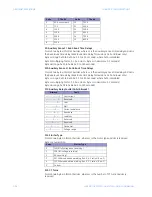
F7: Power Transformer
Format: two bytes in format 0xHHLL, where LL is the PT ratio and HH is reserved
Byte LL enumeration:
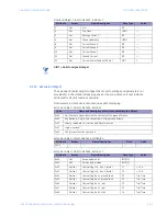
F8: Current Transformer
Format: two bytes in format 0xHHLL, where LL is the CT ratio and HH is reserved
Byte LL enumeration:
Value
PT Ratio
Value
PT Ratio
0
200:120
6
3300:120
1
240:120
7
4200:120
2
480:120
8
4800:120
3
600:120
9
5400:120
4
2400:120
10
6000:120
5
3000:120
11
7200:120
Value
CT Ratio
Value
CT Ratio
1
27 A sensor pack
9
250:5
Содержание LM10
Страница 6: ...1 IV LM10 MOTOR PROTECTION SYSTEM INSTRUCTION MANUAL TABLE OF CONTENTS ...
Страница 18: ...1 12 LM10 MOTOR PROTECTION SYSTEM INSTRUCTION MANUAL SPECIFICATIONS CHAPTER 1 INTRODUCTION ...
Страница 50: ...4 44 LM10 MOTOR PROTECTION SYSTEM INSTRUCTION MANUAL MOTOR START STOP LOGIC CHAPTER 4 FUNCTIONALITY ...
Страница 70: ...5 64 LM10 MOTOR PROTECTION SYSTEM INSTRUCTION MANUAL SERIAL PORT CHAPTER 5 COMMUNICATIONS ...
Страница 74: ...6 68 LM10 MOTOR PROTECTION SYSTEM INSTRUCTION MANUAL WARRANTY CHAPTER 6 MISCELLANEOUS ...
Страница 102: ...A 28 LM10 MOTOR PROTECTION SYSTEM INSTRUCTION MANUAL LM10 AND ALLEN BRADLEY SLC500 VIA DEVICENET CHAPTERA ...
Страница 106: ...I 4 LM10 MOTOR PROTECTION SYSTEM INSTRUCTION MANUAL INDEX ...


