CHAPTER 4: INTERFACES
FRONT PANEL INTERFACE
L60 LINE PHASE COMPARISON SYSTEM – INSTRUCTION MANUAL
4-31
4
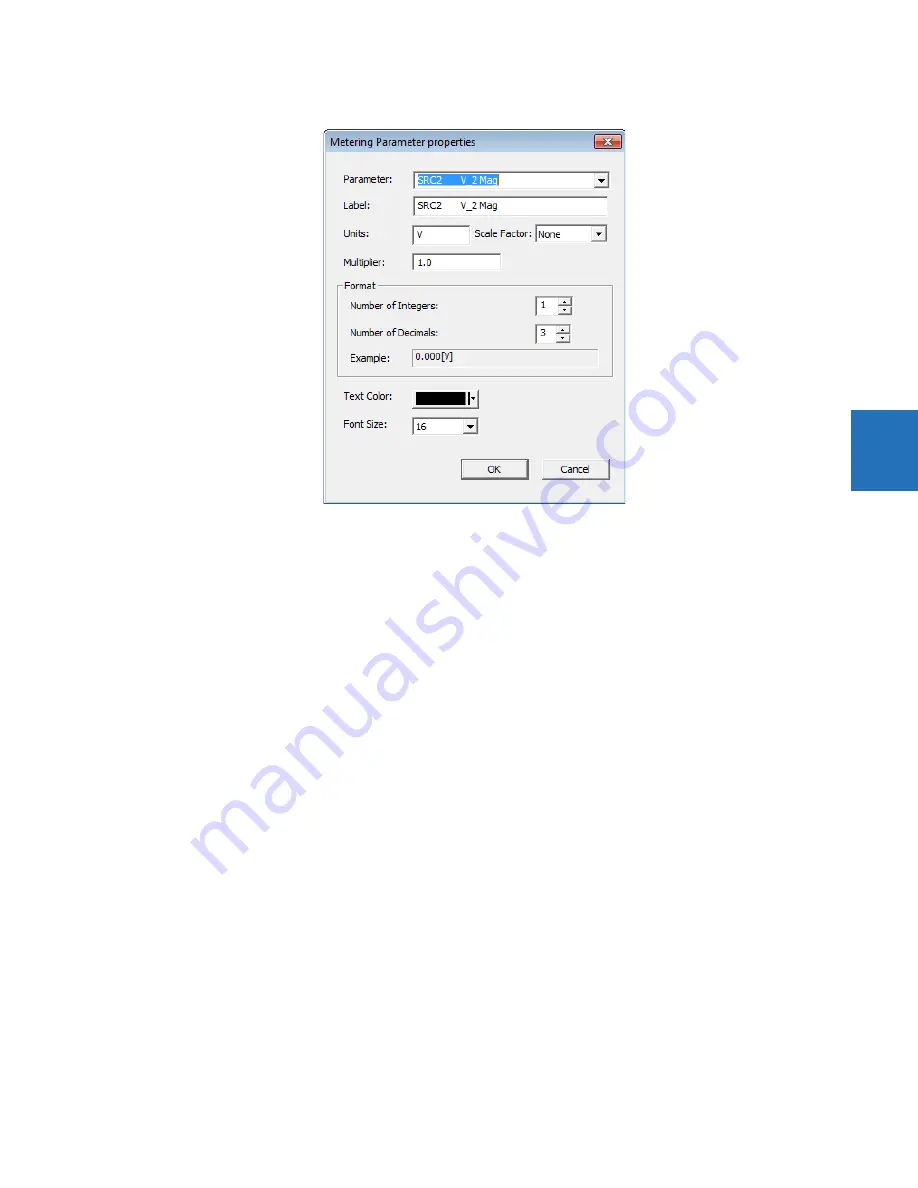
Figure 4-38: Metering properties
Status components
Status components show dynamically the value of a FlexLogic operand. Up to 16 can be used in a diagram and 30 in all
single-line diagrams.
An example is to show the Off or On state of the
ANY MAJOR ERROR
FlexLogic operand. The name of the operand displays in
the single-line diagram editor, then as Off or On on the graphical front panel.
To add a status component, click the S symbol in the toolbox, then click in the window. Drag it to its final location. Double-
click it to open the properties window. Properties that can be edited include parameter (any FlexLogic operand), text color
background color, and on and off text.
Optionally add a text label to display beside the status.
Text
Text components show a single line of user-configured text.
Up to 16 text components can be used per single-line diagram.
To add a text component, click the T symbol in the toolbox, then click in the window. Drag it to its final location. Double-
click it to open the properties window. Properties that can be edited are text, color, and size.
Annunciator
An annunciator is a grid of small windows for alarms, actual values, self-test messages, and product information.
The graphical front panel emulates a conventional annunciator panel. The annunciator has 96 windows, each with a
description of the alarm condition that lights the window. The windows are arranged in rows and columns of 3 x 4, 4 x 6, or
6 x 8 over several pages. Each window can have up to three lines of configurable text, and one line can instead be a
metered value. Normally the window background is dark, and when the configured FlexLogic operand becomes On, the
window lights up.
The figure shows that two alarms are active. One alarm is configured red and the other alarm is configured blue. The red
alarm type is Self Reset, so the alarm displays in a solid color. The blue alarm type is Acknowledgeable, so the alarm flashes
until it is acknowledged, for example by navigating with the arrow keys and pressing the
ENTER
button. The alarm then
remains blue until the trigger condition is eliminated.
Содержание L60
Страница 10: ...x L60 LINE PHASE COMPARISON SYSTEM INSTRUCTION MANUAL TABLE OF CONTENTS ...
Страница 14: ...1 4 L60 LINE PHASE COMPARISON SYSTEM INSTRUCTION MANUAL FOR FURTHER ASSISTANCE CHAPTER 1 INTRODUCTION 1 ...
Страница 122: ...3 72 L60 LINE PHASE COMPARISON SYSTEM INSTRUCTION MANUAL CONNECT TO D400 GATEWAY CHAPTER 3 INSTALLATION 3 ...
Страница 590: ...5 382 L60 LINE PHASE COMPARISON SYSTEM INSTRUCTION MANUAL TESTING CHAPTER 5 SETTINGS 5 ...
Страница 632: ...7 12 L60 LINE PHASE COMPARISON SYSTEM INSTRUCTION MANUAL TARGETS MENU CHAPTER 7 COMMANDS AND TARGETS 7 ...
Страница 736: ...A 14 L60 LINE PHASE COMPARISON SYSTEM INSTRUCTION MANUAL FLEXANALOG ITEMS APPENDIX A FLEXANALOG OPERANDS A ...
Страница 744: ...C 6 L60 LINE PHASE COMPARISON SYSTEM INSTRUCTION MANUAL COMMAND LINE INTERFACE APPENDIX C COMMAND LINE INTERFACE C ...
Страница 752: ...iv L60 LINE PHASE COMPARISON SYSTEM INSTRUCTION MANUAL ABBREVIATIONS ...


