Publication No. IPN250RTM-HRM/2
Connectors 19
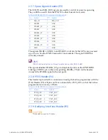
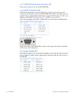
2.3.7 Spare Signals Header (P3)
The
SEQ_IN
and
SEQ_OUT
signals
are
used
for
control
of
power
sequencing.
They
could
be
used
to
link
the
IPN250
to
other
boards
in
a
system.
The
signals
SPARE
1,
SPARE
2
and
SPARE
3
control
whether
GPUs
are
powered
up
or
down.
See
the
IPN250
manual
for
more
details.
The
signal
SPARE4
is
currently
unused.
LINK
IPN250 Hardware Reference Manual, publication number IPN250-HRM.
The
signals
labelled
SPAREx_TP
go
to
simple
test
points
on
the
IPN250RTM.
Linking
a
SPAREx
pin
to
the
corresponding
SPAREx_TP
pin
on
the
header,
connects
the
SPAREx
signal
to
the
test
point.
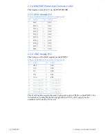
2.3.8 P3V3 Header (P4)
This
header
is
provided
for
convenience
in
using
the
Lattice
programmer
with
the
JTAG
Header
(P2).
All
pins
on
P4
are
connected
to
P3V3_AUX
so
that
the
Lattice
programmer
can
use
any
of
them.
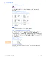
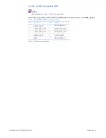
2.3.9 Dediprog Interface Header (P5)
CAUTION
This header is now a no-fit option.
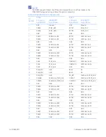
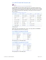
Table 2-8 IPN250RTMA P3 Header Pin Assignments
Pin
Signal
Pin
Signal
1
SEQ_IN
2
SEQ_OUT
3
SPARE1
4
GND
5
SPARE1_TP
6
GND
7
SPARE2
8
GND
9
SPARE2_TP
10
GND
11
SPARE3
12
GND
13
SPARE3_TP
14
GND
15
SPARE4
16
GND
17
SPARE4_TP
18
GND
19
GND
20
GND
Table 2-9 IPN250RTMA P4 Header Pin Assignments
Pin
Signal
Pin
Signal
1
P3V3_AUX
2
P3V3_AUX
3
P3V3_AUX
4
P3V3_AUX
5
P3V3_AUX
6
P3V3_AUX
7
P3V3_AUX
8
P3V3_AUX
Содержание IPN250RTM
Страница 1: ...Hardware Reference Manual IPN250RTM Edition 2 Publication No IPN250RTM HRM 2 GE Intelligent Platforms ...
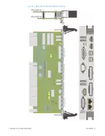
Страница 10: ...10 IPN250RTM Publication No IPN250RTM HRM 2 Figure 1 2 IPN250RTMB ...
Страница 11: ...Publication No IPN250RTM HRM 2 IPN250RTM 11 Figure 1 3 IPN250RTMA and IPN250RTMB Assembly ...

