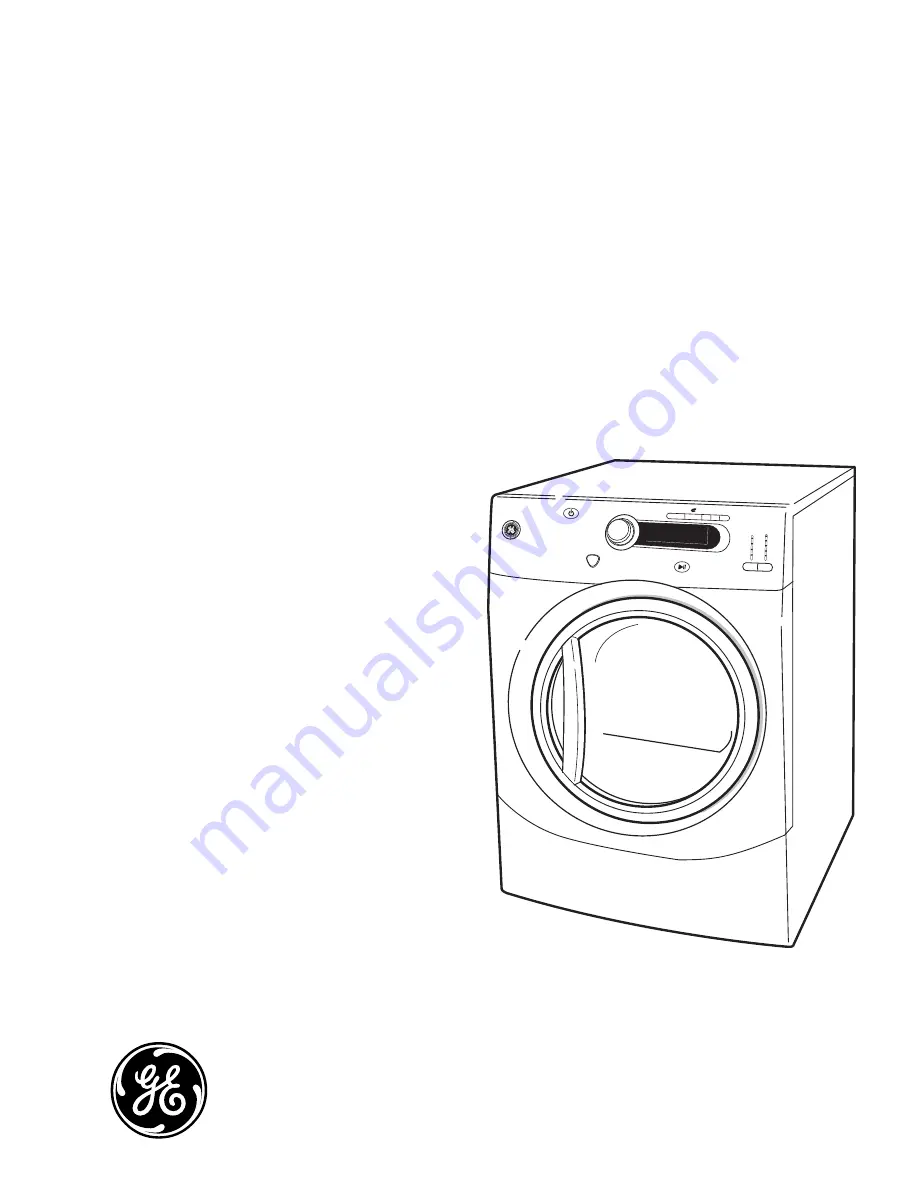
background image

GE Appliances

General Electric Company

Louisville, Kentucky 40225

31-9209

GFDS350
GFDS355
GFDN240
GFDN245

Technical Service Guide

March 2011

GE Appliances

GE HA Dryer With Mist

ACTIVE WEAR

SPEED DRY

PAUSE

COTTONS

NORMAL /

MIXED LOAD

TIME DRY

SENSOR DRY

TIME DRY

WARM UP

AIR FLUFF

DELICATES

P

OWER

L

EVEL

T

EMP

S

TART

EASY CARE

STEAM

REFRESH

STEAM

DEWRINKLE

MY CYCLE

SIGNAL

LOCK

Содержание GFDN240

Страница 1: ...S355 GFDN240 GFDN245 Technical Service Guide March 2011 GE Appliances GE HA Dryer With Mist ACTIVE WEAR SPEED DRY PAUSE COTTONS NORMAL MIXED LOAD TIME DRY SENSOR DRY TIME DRY WARM UP AIR FLUFF DELICATES POWER LEVEL TEMP START EASY CARE STEAM REFRESH STEAM DEWRINKLE MY CYCLE SIGNAL LOCK ...

Страница 2: ...the information in this manual is not followed exactly fire or explosion may result causing property damage personal injury or death If you smell gas Do not try to light any appliance Do not touch any electrical switch do not use any phone in the building Immediately call the gas supplier from a neighbor s phone Follow the gas supplier s instructions If you cannot reach the gas supplier call the f...

Страница 3: ... Drive Belt 32 Drum 33 Drum Light Receptacle 30 Drum Shaft and Bearing 33 Drum Slide Assembly 29 Dryer Components 27 Electronic Control 45 Flame Detector 40 Front Panel 28 Gas Valve 39 Gas Valve Coils 38 Heater Assembly 37 High Limit Thermostat 44 Idler Assembly 33 Ignitor 40 Ignitor Circuit Operation 41 Inlet Control Thermistor 42 Inlet Safety Thermostat 42 Introduction 5 Moisture Sensor 31 Motor...

Страница 4: ...ntrol Thermistor 43 Reversing the Door Swing 13 Schematics and Wiring Diagrams 50 Service Test Mode 46 Stacking Instructions 17 Steam Nozzle 30 Strip Circuit 52 Top Panel 27 Troubleshooting 46 Warranty 53 Water Inlet Valve 34 Water Line Connection 7 ...

Страница 5: ...ic care My Cycles Custom cycle that can be set for specific or frequent needs 24 hour Delay Start Set the dryer to begin cycles whenever it s convenient for you Active Wear cycle Specific settings to take special care of clothing worn for active sports Introduction exercise Speed Dry Quickly dries items and small loads for families on the go Up to 90 ft venting capability Has long equivalent ducti...

Страница 6: ...e BB Black MV Metallic Red MG Metallic Gold MS Metallic Block Model Year Designator V 2011 Fuel E Electric G Gas Series Nomenclature Serial Number The first two characters of the serial number identify the month and year of manufacture Example AV123456S January 2011 A JAN 2011 V D FEB 2010 T F MAR 2009 S G APR 2008 R H MAY 2007 M L JUN 2006 L M JUL 2005 H R AUG 2004 G S SEP 2003 F T OCT 2002 D V N...

Страница 7: ... flat washer is in place Tighten by hand until firmly seated 4 Insert the filter screen in the coupling of the washer s inlet hose If a rubber flat washer is already in place remove it before installing the filter screen Attach this coupling to one male end of the Y connector Tighten by hand until firmly seated 5 Ensure the rubber flat washer is in place and attach the dryer s long inlet hose to t...

Страница 8: ...ol panel You can locate your model number at the top inside of the door opening Model GFDN240 245 1 SPEED DRY NORMAL MIXED LOAD EASY CARE DELICATES ACTIVE WEAR COTTONS DEWRINKLE TIME DRY AIR FLUFF NO HEAT 2 3 8 6 4 5 7 Model GFDS350 355 1 SENSOR DRY 3 4 5 6 2 7 8 ...

Страница 9: ...eat DEWRINKLE on some models For removing wrinkles from items that are dry or slightly damp This cycle is not recommended for delicate fabrics STEAM REFRESH on some models For slightly wrinkled dry garments Significantly reduces wrinkles on up to 5 garments After the STEAM REFRESH Cycle the unit will beep and display 0 00 If the unit is not turned off or if the door is not opened the dryer will co...

Страница 10: ...rature of your dry cycle 6 START Press to start a dry cycle If the dryer is running press it once and it will pause the dryer Press it again to resume the dry cycle My Cycle Set up your favorite combination of settings and save them here for one touch recall These custom settings can be set while a cycle is in progress To store a MY CYCLE combination of settings 1 Select your drying cycle 2 Change...

Страница 11: ...your dryer 1 Choose your dry cycle and any options 2 Press DELAY START You can increase the delay time in 1 hour increments using the DELAY START button 3 Press the START pad to start the countdown NOTES If the door is opened while the dryer is in DELAY START the countdown time will not restart unless the door is closed and START has been pressed again e DRY Reduces the total energy consumption of...

Страница 12: ... 12 ...

Страница 13: ... completed These instructions are for changing the hinges from the right side to the left side if you ever want to switch them back to the right side follow these same instructions and reverse all references to the left and right TOOLS YOU WILL NEED Adjustable Crescent Wrench Phillips Head Screwdriver Putty Knife or Thin Blade Screwdriver DOOR PARTS Hinge Cover Plastic Cover STEP BY STEP INSTRUCTI...

Страница 14: ...or resting on handle side Remove the 8 tapping screws located around the perimeter of the door outlining the gasket Remove the 6 machine screws Using a putty knife or any other flat tool remove the 2 beauty buttons and install them on the opposite side Remove Top Screw 8 8 Tapping Screws 6 8 Machine Tapping Screws 4 Beauty Buttons Outer Door Assembly Hinge Assembly Hinge Cover Remove Hinge and Cov...

Страница 15: ...n Push the hinge assembly in place until the hinge holes align with the door holes 8 Hold the hinge and door on their side with one hand and fasten the 6 machine screws as shown Reinstall Hinge Cover 9 Insert the hinge cover Align the hinge cover holes with the holes in the door 10 Secure the hinge cover with 2 taping screws Machine screws Hinge Cover Tapping Screws ...

Страница 16: ...uttons located on the dryer where the door will be installed and install them on the opposite side 14 Switch the strike bracket and its cover to the opposite side by removing the screws Reinstall both on the opposite side Beauty Buttons Tapping Screws Reinstall Door Assembly 15 The door is now ready to be installed on the dryer To ease this step the hinge has keyholes that allow a partially fasten...

Страница 17: ...sult in personal injury death or property damage Mobile Home or Manufactured Home Installation Stacking of a gas dryer is not permitted in a mobile home or manufactured home MINIMUM CLEARANCE OTHER THAN ALCOVE OR CLOSET INSTALLATION Minimum clearance to combustible surfaces and for air opening are 0s both sides 1s front and 3s rear Consideration must be given to provide adequate clearance for inst...

Страница 18: ...1 2 Screws TOOLS YOU WILL NEED Phillips Screwdriver Open Ended Wrench Pliers Gloves Level INSTALLATION PREPARATION Remove the packaging Flatten the product carton to use as a pad to lay the dryer down on its side Continue using the carton to protect the finished floor in front of the installation location Continued Next Page ...

Страница 19: ... the adhesive backing and firmly place over on the bracket where you removed the leveling legs 3 Install Bracket to Dryer A Align the holes in the left bracket with the holes in the bottom left corner of the dryer Use a Phillips screwdriver to install the 2 12 x 1s tapping screws B Repeat the above step with the right bracket on the bottom right corner of the dryer C Set the dryer upright NOTE Mak...

Страница 20: ...l panel WARNING Potential Personal Injury More than two people are recommended to lift the dryer into position because of its weight and size Failure to do so could result in personal injury or death B Align the holes in the bracket with the holes in the back of the washer Using a Phillips screwdriver attach the 2 8 x 1 2s tapping screws Repeat on both sides of the washer 6 Finalize the Installati...

Страница 21: ...ensor Heater Pan Electric Elements Gas Combustion Chamber Dryer Air Flow System The typical dryer cycle progresses as follows 1 A cycle is selected and the start key is pressed 2 The motor is activated 3 The heater elements burner for gas models are activated The elements burner cycle on and off to achieve the desired temperature throughout the heating portion of the cycle 4 If sensor drying is se...

Страница 22: ... 22 Airflow ...

Страница 23: ...mble with heat Tumble with heat Water Valve on Heat off Tumble with heat Water Valve on Heat off Tumble with heat Cool Down End of Cycle On Tumble Off On Heat Off On Valve Off Steam De wrinkle Steam Refresh Time Times based on Cycle Large or Small Steam De wrinkle Water Valve on and Heat off Extended Tumble if option selected Time Times based on Cycle Large or Small Steam Refresh Water Valve on an...

Страница 24: ... Page Inlet Safety Thermostat Heater Assembly Inlet Control Thermistor Power Board Idler Pulley Water Valve inside cover Outlet Control Backup Thermostat under shield Motor under shield High Limit Thermostat Blower Wheel Outlet Control Thermistor behind frame ...

Страница 25: ...er shield Inlet Safety Thermostat Blower Wheel Inlet Control Thermistor Outlet Control Thermistor behind frame High Limit Thermostat Water Valve inside cover Motor under shield Outlet Control Backup Thermostat Idler Pulley Power Board ...

Страница 26: ...ycle Selector Dryness Selector Temperature Selector LED Display Start Pause Switch J1 Door Switch J2 Drum Motor J3 User Interface J4 Outlet Control Thermistor and Inlet Control Thermistor J5 Model Selector J7 Moisture Sensor Rods J9 Outer Coil L1 Electric Heat Line Gas Heat J8 Outer Coil Relay J10 Inner Coil L1 Electric Heat J20 Water Valve J21 Water Valve Relay J9 J2 J21 J1 ...

Страница 27: ...o remove the top panel 1 Remove the Phillips head screw that attaches the control panel rear trim Pull the trim backward and remove Note It may be helpful to place a putty knife along the top seam between the cover and the control panel then tap lightly backward Control Panel Removal of the control panel provides access to the control board assembly To remove the control panel 1 Remove the cycle s...

Страница 28: ... head screws from the front panel bracket Disconnect Disconnect 4 Remove 4 Phillips head screws from the front panel bracket 5 Lift the bracket out of the hinges and set aside Note In the following step it may be necessary to raise the front of the dryer to gain access to the screws 6 Loosen but do not remove the 2 Phillips head screws from the bottom of the front panel 7 Remove 2 Phillips head sc...

Страница 29: ...nd remove the drum slide Support Slides Guide Slide Guide Slide Tab Tab 3 Remove the single Phillips head screw that attaches the drum light receptacle and remove the receptacle from the drum glide assembly Caution Upon reassembly ensure that the door switch drum light and sensor wiring are retained and routed properly to avoid contact with the drum Air Duct Assembly The air duct assembly houses t...

Страница 30: ...ryer door to access the steam nozzle A 7 16 or 11 mm nut driver can be used to unscrew the nozzle from the air duct assembly To replace the steam nozzle connector 1 Remove the air duct assembly See Air Duct Assembly 2 Press on the John Guest connector collar and release the water line from the steam nozzle connector 3 Remove the Phillips head screw that attaches the nozzle to the nozzle housing St...

Страница 31: ...mately 5 VDC when the circuit is open and discharges to less than 1 VDC when the circuit is shorted When wet clothes tumble across the two rods the clothes create a very low resistance between the rods which discharges the capacitor As the clothes become dry their resistance value increases and the charge across the capacitor builds to approximately 5 VDC Proper leveling of the dryer is vital for ...

Страница 32: ...r clarity Belt Installed on Pulleys 3 Remove the belt from the motor pulley and remove through the front of the dryer To install the drive belt 1 Remove the front panel See Front Panel 2 Reach under the left hand side of the drum push the idler pulley down and to the right and lock the pulley shaft on the top corner of the motor bracket See photo 3 Place the belt in position around the center of t...

Страница 33: ...g it is necessary to remove the drum See Drum Drum Shaft Bearing Idler Assembly The idler assembly maintains proper tension on the belt to minimize belt slippage The idler assembly consists of an idler pulley that rotates on an idler arm The pulley is retained on the arm using a cap nut The idler arm is positioned on the chassis and inserted in a slot in the motor base plate The assembly is locate...

Страница 34: ...il wiring 5 Press the John Guest connector collar and remove the water outlet tubing Water Inlet Hose Disconnect Water Outlet Tubing John Guest Connector Collar Motor and Blower Wheel The motor is a single speed dual shaft 1 4 hp 1725 rpm motor with an automatic reset overload protector The overload protector is an internal component of the motor and cannot be replaced separately The motor contain...

Страница 35: ...Outlet Control Backup Thermostat Motor Moisture Shield 11 Raise the rear of the motor bracket to clear the tab protruding from the bottom of the chassis Slide the motor bracket back until the bracket tabs clear the slots in the chassis Remove the motor and blower wheel assembly from the chassis Note When installing the motor and blower wheel assembly ensure that the 2 rear tabs on the motor bracke...

Страница 36: ... motor strap 15 Lift and remove the motor from the motor bracket Belt Switch The belt switch is fastened to the motor base plate with 2 Phillips head screws The belt switch is activated by the movement of the idler arm If the drive belt breaks or comes off the idler pulley the belt switch opens power to the motor interrupting dryer operation The drum lamp will operate with an open belt switch To r...

Страница 37: ...r assembly 1 Remove the drum See Drum 2 Disconnect the leads from the heater Blower Housing The blower housing is attached to the dryer with 7 screws and 3 tabs To remove the blower housing 1 Remove the motor and blower wheel See Motor and Blower Wheel 2 Remove the single Phillips head screw located inside the outlet of the exhaust pipe Remove the exhaust pipe from the blower housing 3 Remove the ...

Страница 38: ...See Drum 2 Remove 2 Phillips head screws from the front frame and the Phillips head screw from the rear of the gas valve cover 4 Note the position of the locator pins inserted in the coil bracket 5 Remove the 2 Phillips head screws that attach the coil bracket to the valve body Burner Assembly and LP Conversion The burner assembly consists of the gas valve coils gas valve burner and inlet pipe To ...

Страница 39: ...om the front frame and the Phillips head screw from the rear of the gas valve cover Gas Valve Moisture Shield 5 Disconnect the ignitor wire harness and the 2 wires from the flame detector 6 Disconnect the coil wire harness from each coil 7 Remove the 2 Phillips head screws that attach the gas valve bracket to the dryer floor 8 Pull the bracket toward the front of the dryer to disengage tabs from d...

Страница 40: ...to the slot located on the combustion chamber Ignitor The ignitor is located at the end of the burner assembly in the combustion chamber opening and has a maximum rating of 4 amps The ignitor has an approximate resistance value of 300 to 500 Ω The ignitor is attached to the gas valve bracket with a Phillips head screw To access the ignitor it is necessary to remove the burner assembly See Gas Valv...

Страница 41: ... Safety thermostats to the gas valve 2 Neutral circuit is from the dryer harness through the door switch and motor switch M2 to M1 to the gas valve When the glo bar is heating the booster and safety coils are both energized and will open the safety valve The main valve is closed as its coil is bypassed by the N C flame detector When the glo bar reaches ignition temperature in approximately 60 seco...

Страница 42: ...right side of the diffuser below the inlet safety thermostat The thermistor monitors incoming air temperature and will respond to temperature changes of 3 F The thermistor relays this information to the control board The thermistor has a negative coefficient As the temperature increases the thermistor s resistance decreases Electric Model Shown Inlet Safety Thermostat Thermistor Resistance Values ...

Страница 43: ...reducing the maximum heating power typically 50 so that thermostats are fast enough to shut down the heater in case of overheating On GE dryers both heaters are cycled on and off every minute Outlet Control Thermistor Electric Model Shown To remove the inlet control thermistor 1 Remove the drum See Drum 2 Disconnect the 2 wires from the inlet control thermistor 3 Remove the Phillips head screw tha...

Страница 44: ...s located on the top right area of the heater housing On gas models the high limit thermostat is located on the upper right side of the diffuser The high limit thermostat monitors incoming air temperature If the thermostat reaches a temperature beyond its maximum temperature rating it will trip and take out the L1 circuit to the motor disabling the heat source For both gas and electric models the ...

Страница 45: ...ve the electronic control board 1 Set the control panel in the service position See Control Panel 2 Remove the 6 Phillips head screws that attach the selector board to the control panel Power Board Control Board To remove the electronic power board 1 Remove the top panel See Top Panel 2 Disconnect 11 wires and wiring harnesses from the power board 3 Remove the 2 Phillips head screws to release the...

Страница 46: ...Version info Start Pause Knob Knob Knob Knob Power Display the current version of software Turn the knob CW while the display shows the UI SW version The display will alternate between SPb and the 3 digit MC SW version displaying each for 1 second at a time Turn the knob CW while the display shows the MC SW version The display will alternate between EUI and the 3 digit UI Eeprom version displaying...

Страница 47: ...y The UI and MC board will test their respective Eeproms When the UI and MC have finished UIP will be displayed on the SSD if the UI passed or UIF if the UI Eeprom test failed Turn the knob PBP will be displayed on the 7 segment LEDs if the MC passed or PBF if the MC Eeprom test failed Returns to service mode screen T04 UI test Start Pause Any button but power Power The control shall turn on all L...

Страница 48: ... DRY SNAGS ON GARMENT FRONT INLY IS CAUSED BY NORMAL WEAR OR DAMAGE BY COUNTER DESKS ETC CHECK DRUM SPEED EXHAUST SYSTEM CUSTOMER USAGE NOTE 2 CHECK WIRING Note Heater element is shown on wiring schematic on reverse side of this sheet Check for infinite resistance between any heater terminal and dry cabinet Heater failure could result from low air flow caused by improper sealing kinked or excessiv...

Страница 49: ...GE BY COUNTER DESKS ETC EXCESSIVE OR RESTRICTED EXHAUST SYSTEM SAFETY THERMOSTATS BACKUP THERMOSTAT SYNTHETICS ONLY DRUM INTERIOR SURFACES DRUM GAP DAMAGE NO GAS VALVE GAS PRESSURE GAS RESTRICTION YES NO SNAGS ONLY KNITS SNAGS FRONT ONLY NO DISPLAY TIMER OPERATES EXCESSIVE OR RESTRICTED EXHAUST SYSTEM THERMOSTAT TEMPERATURE DISPLAY TIMER OPERATION WASHER SPIN SPEED CHECK Note Other factors contrib...

Страница 50: ...1 J20 RED ORANGE BLACK WHITE BROWN BROWN PINK RED ORANGE WHITE WHITE WHITE WHITE BLUE BLUE WHITE WHITE ORANGE WHITE BLUE PURPLE BLACK RED ORANGE ORANGE ORANGE BLACK RED BROWN GRAY BLACK BROWN BROWN 189D7173P001 REV 1 7 J17 START P o 66 ub N 31 1 49 THERMOSTAT OPEN TEMPERATURE F TEMPERATURE C CLOSE OPEN CLOSE OUTLET CONTROL BACKUP HIGH LIMIT SAFETY 165 5 315 10 225 5 155 5 250 15 195 7 74 3 157 6 1...

Страница 51: ...N STEAM 7 5 FE Module 1 3 ORANGE YELLOW WHITE WHITE YELLOW PURPLE PURPLE J21 J20 BLACK RED RED RED RED BLACK BLUE BLUE WHITE WHITE WHITE WHITE BLACK WHITE WHITE WHITE WHITE WHITE WHITE RED RED J2 4 BLACK ORANGE PURPLE PURPLE PINK GREEN BROWN BROWN BROWN BROWN YELLOW RED WHITE WHITE RED GRAY PINK GRAY PINK GRAY GREEN J21 J20 BROWN 189D7173P002 REV 2 1 1 4 Pub No 3 66 8 ...

Страница 52: ... GE BROWN PINK GR AY BLACK BROWN 7 J17 START To check heaters 1 Disconnect power 2 Measure resistance between J9 and J10 Note If both heaters are intact reading should be 40 K6 ORANGE WHITE BLUE PURPLE To check water valve 1 Disconnect power 2 Measure resistance between J20 and plug Note The resistance of the valve coil should read 400 STEAM K9 WHEN USED J2 4 J21 BLACK RED BROWN To check door swit...

Страница 53: ...al damages This warranty gives you specific legal rights and you may also have other rights which vary from state to state To know what your legal rights are consult your local or state consumer affairs office or your state s Attorney General Warrantor General Electric Company Louisville KY 40225 All warranty service provided by our Factory Service Centers or an authorized Customer Care technician...

Отзывы: