GEH-5304A
15
2.
When intended for use on a power supply other than “A”, “C”, “D”, “E” or “K”, the motor will
be identified as follows:
M / N F - V - H - L
Where
M
=
A digit indicating total pulses per cycle
N
=
A digit indicating controlled pulses per cycle
F
=
Free wheeling (this letter appears only if free wheeling is used)
V
=
Three digits indicating nominal line-to-line AC voltage to the rectifier
H
=
Two digits indicating input frequency in hertz
L
=
One, two or three digits indicating the series inductance in millihenries (may
be zero) to be added externally to the motor armature circuit inductance.
D.
Connections
Terminal connections should be checked against the connection diagram shipped with the machine. Bolted
connections must be tight. All exposed connections in the conduit box must be insulated. When more than
one terminal is marked with the same identification, they should be joined in the same connection. (Refer to
Table 6 for identification of wiring leads.)
E.
Protective Devices
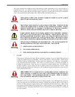
Make certain that all protective devices (overspeed devices, bearing tempera-
ture relays, etc.) are connected and function properly. Also, make certain that
all coupling guards, shaft protectors, grounding connectors, covers and other
safety devices are properly attached.
F.
Motor Field Heating
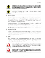
MOTOR FIELD HOUSING – Unless specifically ordered, motors are NOT capable
of continuous standstill excitation at rated field current. When the motor is shut
down for more than 30 minutes, one of the following options must be used:
1. De-energize the fields completely.
2.
Use field economy relays to limit the field current to a maximum of 50% of
the nameplate rating.
3.
When applicable, fields may remain fully energized if the motor ventilation
system (blower or customer duct) remains in operation.
G.
Thermostats
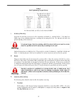
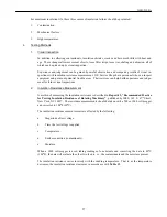
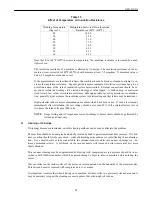
The thermostat is a device that may be used in alarm or protective relay circuits within rating limits shown
in Table 5. It is not intended to limit motor loading or provide normal insulation life. When supplied, it is
mounted to a commutating coil which is the only accessible part of the armature circuit. Since factors such
as shaft speed, ventilation (blower or shaft fan), current ripple (SCR phase-back) and short-time overload
affect the temperature relationship between armature and commutating field, complete protection from all
conditions resulting from over-temperature is not possible. The device is intended to guard against complete
loss of normal ventilation air, high ambient temperature, and prolonged operation of self-ventilated motors
at very low speeds.
Содержание GEH-5304A
Страница 26: ...GEH 5304A 26 ues ...
Страница 34: ...GEH 5304A 34 Figure 3 Application Information for CD2512AT CD2813AT Frames ...
Страница 35: ...GEH 5304A 35 Figure 4 Blower Unit Commutator End Mounted for Use With CD2512AT CD2813AT Frames ...
Страница 36: ...GEH 5304A 36 Figure 5 Dimensions Air Openings for CD2512AT CD2813AT Frames ...
Страница 38: ...GEH 5304A 38 Figure 6 Accessory Mounting CD2512AT CD2813AT ...
Страница 39: ...GEH 5304A 39 Figure 7 Accessory Mounting CD2512AT CD2813AT ...
Страница 40: ...GEH 5304A 40 ...
Страница 41: ...GEH 5304A 41 Type CD Frames 2512AT 2813AT DC Motors Generators Figure 8 Type CD Frames 2512AT 2813AT ...
Страница 43: ...GEH 5304A 43 Detach and fax or mail to the address noted above ...


