6-10
F60 Feeder Protection System
GE Multilin
6.2 STATUS
6 ACTUAL VALUES
6
6.2.17 TELEPROTECTION CHANNEL TESTS
PATH: ACTUAL VALUES
Ö
STATUS
ÖØ
TELEPROT CH TESTS
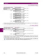
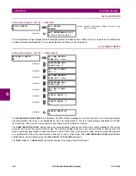
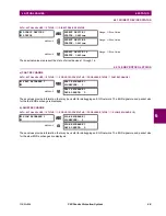
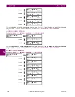
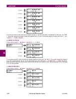
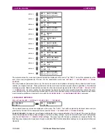
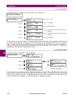
The status information for two channels is shown here.
•
CHANNEL 1 STATUS
: This represents the receiver status of each channel. If the value is “OK”, teleprotection is
enabled and data is being received from the remote terminal; If the value is “FAIL”, teleprotection enabled and data is
not being received from the remote terminal. If “n/a”, teleprotection is disabled.
•
CHANNEL 1 LOST PACKETS
: Data is transmitted to the remote terminals in data packets at a rate of two packets per
cycle. The number of lost packets represents data packets lost in transmission; this count can be reset to 0 through the
COMMANDS
ÖØ
CLEAR RECORDS
menu.
•
VALIDITY OF CHANNEL CONFIGURATION
: This value displays the current state of the communications channel
identification check, and hence validity. If a remote relay ID does not match the programmed ID at the local relay, the
“FAIL” message will be displayed. The “N/A” value appears if the local relay ID is set to a default value of “0”, the chan-
nel is failed, or if the teleprotection inputs/outputs are not enabled.
6.2.18 INCIPIENT FAULT DETECTOR
PATH: ACTUAL VALUES
Ö
STATUS
ÖØ
INCIPIENT FAULT
Ö
INCIPIENT FAULT 1(2)
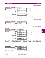
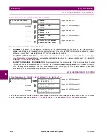
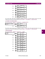
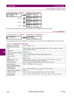
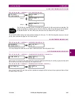
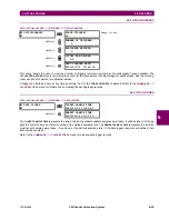
The number of detected incipient faults for each incipient fault element are displayed here for each phase. These values
can be reset to zero with the
COMMANDS
ÖØ
CLEAR RECORDS
ÖØ
CLEAR INCIPENT FAULT COUNTERS
command.
TELEPROT CH TESTS
CHANNEL 1
STATUS: n/a
Range: n/a, FAIL, OK
MESSAGE
CHANNEL 1 LOST
PACKETS:
1
Range: 1 to 65535 in steps of 1
MESSAGE
CHANNEL 2
STATUS: n/a
Range: n/a, FAIL, OK
MESSAGE
CHANNEL 2 LOST
PACKETS:
1
Range: 1 to 65535 in steps of 1
MESSAGE
VALIDITY OF CHANNEL
CONFIGURATION: FAIL
Range: n/a, FAIL, OK
INCIPIENT FAULT 1
INCIPIENT FAULT 1
PH A FAULTS: 0
Range: 0 to 65535 in steps of 1
MESSAGE
INCIPIENT FAULT 1
PH B FAULTS: 0
Range: 0 to 65535 in steps of 1
MESSAGE
INCIPIENT FAULT 1
PH C FAULTS: 0
Range: 0 to 65535 in steps of 1
Содержание F60 UR Series
Страница 2: ......
Страница 4: ......
Страница 30: ...1 20 F60 Feeder Protection System GE Multilin 1 5 USING THE RELAY 1 GETTING STARTED 1 ...
Страница 48: ...2 18 F60 Feeder Protection System GE Multilin 2 2 SPECIFICATIONS 2 PRODUCT DESCRIPTION 2 ...
Страница 96: ...3 48 F60 Feeder Protection System GE Multilin 3 4 MANAGED ETHERNET SWITCH MODULES 3 HARDWARE 3 ...
Страница 126: ...4 30 F60 Feeder Protection System GE Multilin 4 2 FACEPLATE INTERFACE 4 HUMAN INTERFACES 4 ...
Страница 354: ...5 228 F60 Feeder Protection System GE Multilin 5 9 TESTING 5 SETTINGS 5 ...
Страница 382: ...6 28 F60 Feeder Protection System GE Multilin 6 5 PRODUCT INFORMATION 6 ACTUAL VALUES 6 ...
Страница 398: ...8 8 F60 Feeder Protection System GE Multilin 8 2 FAULT LOCATOR 8 THEORY OF OPERATION 8 ...
Страница 414: ...A 14 F60 Feeder Protection System GE Multilin A 1 PARAMETER LIST APPENDIXA A ...
Страница 492: ...B 78 F60 Feeder Protection System GE Multilin B 4 MEMORY MAPPING APPENDIXB B ...
Страница 530: ...D 10 F60 Feeder Protection System GE Multilin D 1 IEC 60870 5 104 APPENDIXD D ...
Страница 542: ...E 12 F60 Feeder Protection System GE Multilin E 2 DNP POINT LISTS APPENDIXE E ...
Страница 558: ...x F60 Feeder Protection System GE Multilin INDEX ...

