5-220
F60 Feeder Protection System
GE Multilin
5.8 TRANSDUCER INPUTS/OUTPUTS
5 SETTINGS
5
5.8TRANSDUCER INPUTS/OUTPUTS
5.8.1 DCMA INPUTS
PATH: SETTINGS
ÖØ
TRANSDUCER I/O
ÖØ
DCMA INPUTS
Ö
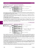
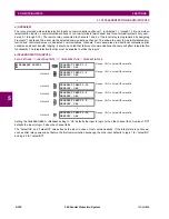
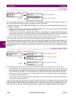
DCMA INPUT H1(W8)
Hardware and software is provided to receive signals from external transducers and convert these signals into a digital for-
mat for use as required. The relay will accept inputs in the range of –1 to +20 mA DC, suitable for use with most common
transducer output ranges; all inputs are assumed to be linear over the complete range. Specific hardware details are con-
tained in chapter 3.
Before the dcmA input signal can be used, the value of the signal measured by the relay must be converted to the range
and quantity of the external transducer primary input parameter, such as DC voltage or temperature. The relay simplifies
this process by internally scaling the output from the external transducer and displaying the actual primary parameter.
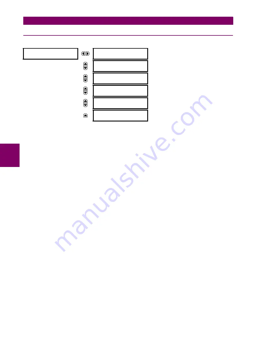
dcmA input channels are arranged in a manner similar to CT and VT channels. The user configures individual channels
with the settings shown here.
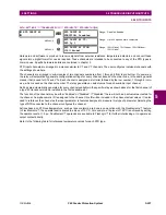
The channels are arranged in sub-modules of two channels, numbered from 1 through 8 from top to bottom. On power-up,
the relay will automatically generate configuration settings for every channel, based on the order code, in the same general
manner that is used for CTs and VTs. Each channel is assigned a slot letter followed by the row number, 1 through 8 inclu-
sive, which is used as the channel number. The relay generates an actual value for each available input channel.
Settings are automatically generated for every channel available in the specific relay as shown above for the first channel of
a type 5F transducer module installed in slot H.
The function of the channel may be either “Enabled” or “Disabled”. If “Disabled”, no actual values are created for the chan-
nel. An alphanumeric “ID” is assigned to each channel; this ID will be included in the channel actual value, along with the
programmed units associated with the parameter measured by the transducer, such as volts, °C, megawatts, etc. This ID is
also used to reference the channel as the input parameter to features designed to measure this type of parameter. The
DCMA INPUT H1 RANGE
setting specifies the mA DC range of the transducer connected to the input channel.
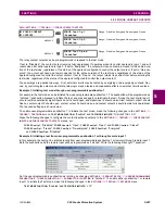
The
DCMA INPUT H1 MIN VALUE
and
DCMA INPUT H1 MAX VALUE
settings are used to program the span of the transducer in
primary units. For example, a temperature transducer might have a span from 0 to 250°C; in this case the
DCMA INPUT H1
MIN VALUE
value is “0” and the
DCMA INPUT H1 MAX VALUE
value is “250”. Another example would be a watts transducer with
a span from –20 to +180 MW; in this case the
DCMA INPUT H1 MIN VALUE
value would be “–20” and the
DCMA INPUT H1 MAX
VALUE
value “180”. Intermediate values between the min and max values are scaled linearly.
DCMA INPUT H1
DCMA INPUT H1
FUNCTION: Disabled
Range: Disabled, Enabled
MESSAGE
DCMA INPUT H1 ID:
DCMA Ip 1
Range: up to 20 alphanumeric characters
MESSAGE
DCMA INPUT H1
UNITS:
μ
A
Range: 6 alphanumeric characters
MESSAGE
DCMA INPUT H1
RANGE: 0 to -1 mA
Range: 0 to –1 mA, 0 to +1 mA, –1 to +1 mA, 0 to 5 mA,
0 to 10mA, 0 to 20 mA, 4 to 20 mA
MESSAGE
DCMA INPUT H1 MIN
VALUE: 0.000
Range: –9999.999 to +9999.999 in steps of 0.001
MESSAGE
DCMA INPUT H1 MAX
VALUE: 0.000
Range: –9999.999 to +9999.999 in steps of 0.001
Содержание F60 UR Series
Страница 2: ......
Страница 4: ......
Страница 30: ...1 20 F60 Feeder Protection System GE Multilin 1 5 USING THE RELAY 1 GETTING STARTED 1 ...
Страница 48: ...2 18 F60 Feeder Protection System GE Multilin 2 2 SPECIFICATIONS 2 PRODUCT DESCRIPTION 2 ...
Страница 96: ...3 48 F60 Feeder Protection System GE Multilin 3 4 MANAGED ETHERNET SWITCH MODULES 3 HARDWARE 3 ...
Страница 126: ...4 30 F60 Feeder Protection System GE Multilin 4 2 FACEPLATE INTERFACE 4 HUMAN INTERFACES 4 ...
Страница 354: ...5 228 F60 Feeder Protection System GE Multilin 5 9 TESTING 5 SETTINGS 5 ...
Страница 382: ...6 28 F60 Feeder Protection System GE Multilin 6 5 PRODUCT INFORMATION 6 ACTUAL VALUES 6 ...
Страница 398: ...8 8 F60 Feeder Protection System GE Multilin 8 2 FAULT LOCATOR 8 THEORY OF OPERATION 8 ...
Страница 414: ...A 14 F60 Feeder Protection System GE Multilin A 1 PARAMETER LIST APPENDIXA A ...
Страница 492: ...B 78 F60 Feeder Protection System GE Multilin B 4 MEMORY MAPPING APPENDIXB B ...
Страница 530: ...D 10 F60 Feeder Protection System GE Multilin D 1 IEC 60870 5 104 APPENDIXD D ...
Страница 542: ...E 12 F60 Feeder Protection System GE Multilin E 2 DNP POINT LISTS APPENDIXE E ...
Страница 558: ...x F60 Feeder Protection System GE Multilin INDEX ...


