


5-200
F60 Feeder Protection System
GE Multilin
5.6 CONTROL ELEMENTS
5 SETTINGS
5
•
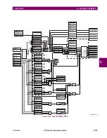
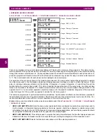
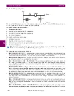
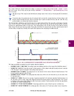
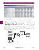
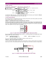
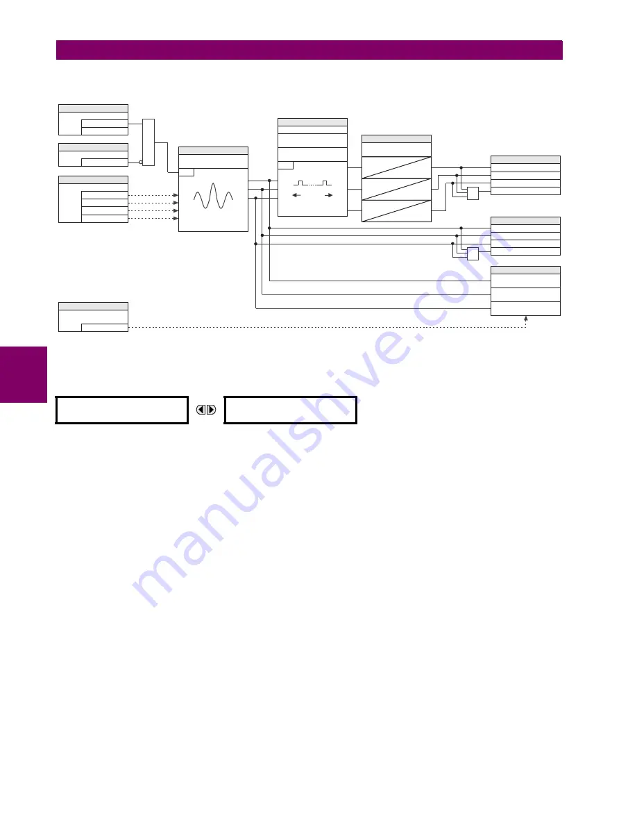
INCIPIENT FAULT 1 RESET DELAY
: This setting specifies a reset time for the output after the trip is initiated.
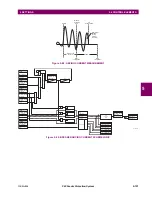
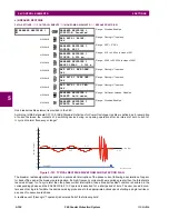
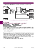
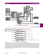
Figure 5–105: INCIPIENT CABLE FAULT DETECTOR SCHEME LOGIC
g) VT FUSE FAILURE
PATH: SETTINGS
ÖØ
CONTROL ELEMENTS
ÖØ
MONITORING ELEMENTS
ÖØ
VT FUSE FAILURE 1(2)
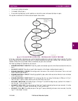
Every signal source includes a fuse failure scheme.
The VT fuse failure detector can be used to raise an alarm and/or block elements that may operate incorrectly for a full or
partial loss of AC potential caused by one or more blown fuses. Some elements that might be blocked (via the
BLOCK
input)
are distance, voltage restrained overcurrent, and directional current.
There are two classes of fuse failure that may occur:
•
Class A: loss of one or two phases.
•
Class B: loss of all three phases.
Different means of detection are required for each class. An indication of Class A failures is a significant level of negative
sequence voltage, whereas an indication of class B failures is when positive sequence current is present and there is an
insignificant amount of positive sequence voltage. These noted indications of fuse failure could also be present when faults
are present on the system, so a means of detecting faults and inhibiting fuse failure declarations during these events is pro-
vided. Once the fuse failure condition is declared, it will be sealed-in until the cause that generated it disappears.
An additional condition is introduced to inhibit a fuse failure declaration when the monitored circuit is de-energized; positive
sequence voltage and current are both below threshold levels.
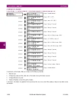
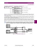
The function setting enables and disables the fuse failure feature for each source.
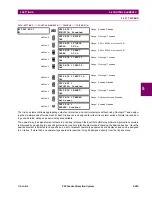
VT FUSE FAILURE 1
VT FUSE FAILURE 1
FUNCTION: Disabled
Range: Disabled, Enabled
Detection logic
SETTING
= Enabled
= Disabled
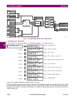
INCIPIENT FAULT 1 FUNCTION
SETTING
= OFF
INCIPIENT FAULT 1 BLOCK
SETTING
= IA
= IB
INCIPIENT FAULT 1 SOURCE
= IC
= IN
AND
SETTING
INCIPIENT FAULT 1
PICKUP
RUN
–
> PICKUP
where
is 2 cycles old
I
mag
´
I
I
mag
mag
´
SETTINGS
INCIPNT FLT 1 DETECT
WINDOW
RUN
INCIPIENT FLT 1 TRIP
COUNTS NUMBER
INCIPNT FLT 1 MODE
T
WINDOW
SETTINGS
INCIPIENT FAULT 1
RESET DELAY
0
T
RST
0
T
RST
0
T
RST
FLEXLOGIC OPERANDS
INCIPNT FLT 1 OP A
INCIPNT FLT 1 OP B
INCIPNT FLT 1 OP C
INCIPNT FLT 1 OP
OR
FLEXLOGIC OPERANDS
INCIPNT FLT 1 PKP A
INCIPNT FLT 1
B
PKP
INCIPNT FLT 1
C
PKP
INCIPNT FLT 1 PKP
OR
ACTUAL VALUES
INCIPIENT FAULT 1 PH B
FAULTS
INCIPIENT FAULT 1 PH A
FAULTS
INCIPIENT FAULT 1 PH C
FAULTS
COMMAND
= Yes
CLEAR INCIPIENT FAULT
COUNTERS
RESET
832028A1.CDR
Содержание F60 UR Series
Страница 2: ......
Страница 4: ......
Страница 30: ...1 20 F60 Feeder Protection System GE Multilin 1 5 USING THE RELAY 1 GETTING STARTED 1 ...
Страница 48: ...2 18 F60 Feeder Protection System GE Multilin 2 2 SPECIFICATIONS 2 PRODUCT DESCRIPTION 2 ...
Страница 96: ...3 48 F60 Feeder Protection System GE Multilin 3 4 MANAGED ETHERNET SWITCH MODULES 3 HARDWARE 3 ...
Страница 126: ...4 30 F60 Feeder Protection System GE Multilin 4 2 FACEPLATE INTERFACE 4 HUMAN INTERFACES 4 ...
Страница 354: ...5 228 F60 Feeder Protection System GE Multilin 5 9 TESTING 5 SETTINGS 5 ...
Страница 382: ...6 28 F60 Feeder Protection System GE Multilin 6 5 PRODUCT INFORMATION 6 ACTUAL VALUES 6 ...
Страница 398: ...8 8 F60 Feeder Protection System GE Multilin 8 2 FAULT LOCATOR 8 THEORY OF OPERATION 8 ...
Страница 414: ...A 14 F60 Feeder Protection System GE Multilin A 1 PARAMETER LIST APPENDIXA A ...
Страница 492: ...B 78 F60 Feeder Protection System GE Multilin B 4 MEMORY MAPPING APPENDIXB B ...
Страница 530: ...D 10 F60 Feeder Protection System GE Multilin D 1 IEC 60870 5 104 APPENDIXD D ...
Страница 542: ...E 12 F60 Feeder Protection System GE Multilin E 2 DNP POINT LISTS APPENDIXE E ...
Страница 558: ...x F60 Feeder Protection System GE Multilin INDEX ...