Aisys
2-18
04/08 M1046983
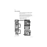
2.7.2 Anesthesia
Control Board
details
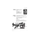
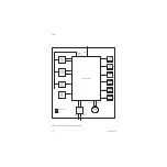
The 12.5 VDC power enters the Anesthesia Controller Board via connector J6
(see item 14 in Section 2.6). This 12.5 VDC is further regulated down to five additional
voltages used by the Anesthesia Controller Board. These include:
• 3.3VDC – VR2
• 1.8VDC – VR3
• 5.0VDC – VR1: Used for Pipeline and Cylinder Pressure Transducers
• 2.5VDC
• 5.0VDC
These voltages are self-monitored for out-of-range.
The Anesthesia Controller Board also supplies 10VA-limited power (+12.5VDC & +5.0
VDC) to External subsystems and Pipeline and Cylinder Pressure Transducers.
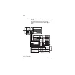
Valve Drivers
The Anesthesia Controller Board contains logic circuits and valve drive circuits for the
following devices that reside on subsystems:
• O
2
Select Valve (Gas Mixer Board)
• N
2
O Select Valve (Gas Mixer Board)
• AIR Select Valve (Gas Mixer Board)
• Alt O
2
Select Valve (Gas Mixer Board)
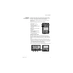
Status LEDs
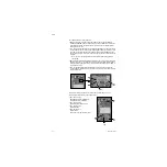
The Anesthesia Controller Board contains 2 sets of 4 each (8 total) status LEDs. They
are located on the board at approximately the 6 and 9 o’clock positions, near
connectors J5 and J6 respectively. Each set contains the following four LEDs:
• RXD (CR19 and CR35) – yellow – Indicating Display Unit communication activity
• TXD (CR20 and CR34) – yellow – Indicating Anesthesia Controller Board
communication activity
• RESET (CR21 and CR36) – Red – Watchdog Reset
• RXD (CR22 and CR33) – yellow – Software LEDs
Connectors:
The Anesthesia Controller Board has five populated connectors:
• J1 – 50-pin connector to (signal) Pan Connector Board.
• J3 – 24-pin connector to (power) Pan Connector.
• J4 – 10-pin connector (JTAG). This is used by Engineering. Not Used by Service.
• J6 – 16-pin connector power in from Power Controller Board.
• J7 - 12-pin connector to (10VA power) display connector (M-Gas)
Alarms
The Anesthesia Controller Board has a backup audio alarm. This is sounded in the
event of communication loss between the Anesthesia Controller Board and Display
Unit.
Содержание Datex-Ohmeda Aisys Carestation
Страница 1: ...Aisys Anesthesia Machine Technical Reference Manual ...
Страница 16: ...Notes xiv 04 08 M1046983 ...
Страница 32: ...Notes 1 16 04 08 M1046983 ...
Страница 35: ...2 Theory of Operation M1046983 04 08 2 3 A M AB 75 098 L H D AB 75 046 J G I F K P O E D B C H N ...
Страница 158: ...Notes 5 20 04 08 M1046983 ...
Страница 288: ...Notes 7 106 04 08 M1046983 ...
Страница 325: ...9 Repair Procedures M1046983 04 08 9 29 The rear inverter A B C ...
Страница 356: ...Notes 9 60 04 08 M1046983 ...
Страница 397: ...10 Illustrated Parts M1046983 04 08 10 41 1 3 4 2 17 15 16 5 6 13 non DES cassette DES cassette 7 8 11 12 10 5 14 18 9 ...
Страница 399: ...10 Illustrated Parts M1046983 04 08 10 43 14 1 2 3 6 5 4 5 8 7 15 16 15 12 17 10 9 11 13 or 18 ...
Страница 401: ...10 Illustrated Parts M1046983 04 08 10 45 14 1 2 3 6 5 4 5 8 7 15 16 18 17 10 9 11 12 13 or ...
Страница 403: ...10 Illustrated Parts M1046983 04 08 10 47 14 15 18 1 2 3 6 5 4 5 8 7 17 10 9 11 15 16 12 13 or 17a 17c 17d 17b 17e ...
Страница 452: ...Notes 10 96 04 08 M1046983 ...
Страница 466: ...11 14 04 08 M1046983 Notes ...
Страница 470: ...Aisys 12 4 04 08 M1046983 12 3 System Schematics 12 3 1 Power Schematic ...
Страница 478: ...Aisys 12 12 04 08 M1046983 12 6 3 Tools Transfer Logs ...
Страница 495: ...12 Service Application M1046983 04 08 12 29 12 10 2 Vaporizer Subsystem Perform Vaporizer Test ...
Страница 497: ......

