background image

Revision D

250 Series Maternal/Fetal Monitor

3-9

2020551-001

Installation: 

Setup

Setup

Loading Strip Chart Recorder Paper

CAUTIONS

LOADING PAPER—The instructions for loading paper into the 
250 Series Monitor 

are different 

than the instructions for loading 

paper into other Corometrics monitors. Improper loading can 
cause paper jams. Follow the instructions carefully.

PAPER TYPE—Do not use 

non

-Corometrics paper or paper 

designed for use with 

other

 Corometrics monitors. Using the 

wrong paper may produce inferior print quality; could result in 
permanent damage to the recorder’s print head; and may void your 
warranty. Refer to Chapter 6, 

“Parts List, Drawings, and 

Replacement” 

for parts information.

STORAGE/TRANSPORT—Paper should be installed in the 
monitor’s strip chart recorder at 

all

 times. This reduces particle 

build-up on the printhead and facilitates opening the recorder 
door.

„

the recorder will not print;

„

the Record indicator flashes on and off every second;

„

three short chimes sound every 3 seconds at a fixed volume of 6; and the 
message

 PAPER INCORRECTLY LOADED, RELOAD WITH BLACK SQUARES 

DOWN

 is displayed overlaying any waveform in the maternal waveform area.

You may temporarily silence a paper-load–error condition by pressing the 

Alarm 

Silence

 button. The audio alarm will be re-issued if the paper-load–error condition 

continues after the specified silence period (re-alarm time). The re-alarm time is 
adjustable from the password-protected 

Install Options Screen 2

. For further 

information, refer to Chapter 11, “Alarms” in the Corometrics 250 Series Operator’s 
Manual.

The monitor also alerts you when paper is running low and when the recorder is 
completely out of paper.

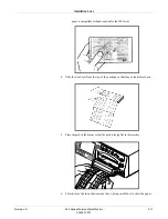
To install Corometrics strip chart paper in the 250 Series Monitor, follow these 
steps:

CAUTION

LOADING PAPER—Paper loading instructions for the 250 Series 
Monitor 

are different

 than other Corometrics Monitors. Improper 

loading can cause paper jams. Follow the instructions carefully.

Содержание Corometrics 250 Series

Страница 1: ...GE Healthcare Corometrics 250 Series Monitor Service Manual Corometrics 250 Series Monitor English 2020551 001 D paper 2006 General Electric Company All Rights Reserved ...

Страница 2: ......

Страница 3: ...GE Healthcare Corometrics 250 Series Monitor Service Manual Corometrics 250 Series Monitor English 2020551 001 D paper 2006 General Electric Company All Rights Reserved ...

Страница 4: ...vious software revisions of Corometrics 250 Series Monitor There are no user apparent differences among these software versions Due to continuing product innovation specifications in this manual are subject to change without notice NOTE For technical documentation purposes the abbreviation GE is used for the legal entity name GE Medical Systems Information Technologies GE Medical Systems Informati...

Страница 5: ...evaluation For systems that include a number of different equipment that perform a number of functions one of each type of equipment shall be included in the evaluation The equipment listed below is representative of all possible combinations For individual equipment certification refer to the appropriate declarations of conformity Component Description 250 Series Maternal Fetal Monitor Model 146 ...

Страница 6: ...CE CE ii 0086 ...

Страница 7: ...omagnetic Interference 1 9 Equipment Symbols 1 10 Service Requirements 1 11 Equipment ID 1 11 Intended Audience 1 11 Intended Use 1 12 Related Manuals 1 13 2 Equipment Overview 2 1 Equipment Description 2 3 Front Panel Description 2 4 Front Panel Displays 2 7 Display Example 2 8 Setup Screens 2 8 Softkeys 2 8 Mode Title Softkeys 2 8 Waveform Softkeys 2 9 Dedicated Softkey Area 2 9 Rear Panel Descr...

Страница 8: ...ls Required 3 3 Connections 3 3 Fetal Acoustic Stimulator 3 3 Remote Marks Connector 3 3 ECG Out Connector 3 3 J101 Connector Model 340 Telemetry System Interface 3 4 J109 J110 and J111 Connectors RS 232C 3 5 Power 3 6 Self Test Routine 3 7 Battery Backed RAM Status 3 8 Setup 3 9 Loading Strip Chart Recorder Paper 3 9 Mounting a Strain Gauge 3 12 Setup Screens 3 12 Service Mode Screens 3 12 Servic...

Страница 9: ...y Tests 4 10 Initial Conditions 4 10 AC Line 4 10 Ground Impedance 4 10 Unit to Primary Leakage 4 10 Patient to Ground Leakage for ECG 4 11 Patient to Line Leakage for ECG 4 12 Patient to Ground Leakage for IUP 4 12 Patient to Line Leakage for IUP 4 13 Patient to Ground Leakage for MSpO2 4 13 Patient to Line Leakage for MSpO2 4 14 Patient to Ground Leakage for US 4 14 Patient to Line Leakage for U...

Страница 10: ...0 MSpO2 Test 4 42 NIBP Calibration and Testing 4 43 Purpose 4 43 Required Hardware 4 43 General Calibration Sequence 4 43 Calibration Verification 4 44 Calibrate Transducers 4 44 Overpressure Detection 4 45 System Leakage 4 45 Display Check 4 45 Checking a Display 4 46 Verifying the DSP Board Operation 4 46 Maternal SpO2 Calibration 4 47 Hardware Switches 4 47 Main Board SW1 Switch Settings 4 48 J...

Страница 11: ...r 4 56 Repair Log 4 57 Preventative Maintenance Inspection Report 4 58 Configuration 4 58 Tools Required 4 58 Visual Inspection 4 58 Comments 4 61 5 Troubleshooting 5 1 Diagnostic Tests 5 3 Main Motherboard and DSP Board Self Test 5 3 Monitor Self Test 5 3 Error Log Screen 5 3 Diagnostic Control Screen 5 5 Recorder Calibration Test 5 6 CPU Version 5 6 DSP Version 5 6 Run Time 5 7 Recorder Time 5 7...

Страница 12: ...025177 010 SpO2 Carrier Board with Nellcor MSpO2 Module 6 12 2025177 011 SpO2 Carrier Board with Masimo MSpO2 Module 6 12 2025177 012 SpO2 Carrier Board with TruSignal MSpO2 Module 6 13 2025177 013 Front end Motherboard 6 14 2025177 014 Chassis 6 15 2025177 016 COMM Board 6 18 2025177 017 Recorder Assembly 6 18 2025177 018 Recorder Board 6 19 2025177 019 Cables 6 21 2025177 020 Pneumatics Assembly...

Страница 13: ... Electromagnetic Compatibility C 1 Electromagnetic Compatibility EMC C 3 Guidance and Manufacturer s Declaration Electromagnetic Emissions C 3 Guidance and Manufacturer s Declaration Electromagnetic Immunity C 4 Recommended Separation Distances C 6 Compliant Cables and Accessories C 7 ...

Страница 14: ...viii 250 Series Maternal Fetal Monitor Revision D 2020551 001 ...

Страница 15: ...you do not know which is the most current For the initial release all pages have the revision letter A For the second update all pages receive the revision letter B The latest letter of the alphabet added to the table below corresponds to the most current revision Revision Date Comment A 29 June 2005 Initial Release B 16 September 2005 Add Gasket Top Cover FRU C 21 March 2006 Update Nellcor change...

Страница 16: ...1 2 250 Series Maternal Fetal Monitor Revision D 2020551 001 For your notes ...

Страница 17: ...e parameters available in the 250 Series of monitors It is the responsibility of each hospital to ensure that the Labor and Delivery staff is trained in all aspects of the selected model The 250 Series Monitor is designed to assist the perinatal staff by providing information regarding the clinical status of the mother and fetus during labor The monitor does not replace observation and evaluation ...

Страница 18: ...NGER notice indicates an imminently hazardous situation which if not avoided will result in death or serious injury Warning A WARNING indicates a potentially hazardous situation which if not avoided could result in death or serious injury Caution A CAUTION indicates a potentially hazardous situation which if not avoided may result in minor or moderate injury Cautions are also used to avoid damage ...

Страница 19: ... personnel must avoid contact with the patient and monitor to avoid a dangerous shock hazard In addition proper placement of the paddles in relation to the electrodes is required to minimize harm to the patient DEFIBRILLATION PROTECTION When used with the GE Medical Systems Information Technologies recommended accessories the monitor is protected against the effects of defibrillator discharge If m...

Страница 20: ...ient care The monitor does not replace observation and evaluation of the patient at regular intervals by a qualified care provider who will make diagnoses and decide on treatments and interventions INTERFACING OTHER EQUIPMENT Monitoring equipment must be interfaced with other types of medical equipment by qualified biomedical engineering personnel Be certain to consult manufacturers specifications...

Страница 21: ...s Do not rely entirely upon rate meter alarms Keep pacemaker patients under close surveillance Refer to Appendix A Technical Specifications for disclosure of the pacemaker pulse rejection capability of the 250 Series Monitor RF INTERFACE Known RF sources such as cell phones radio or TV stations and two way radios may cause unexpected or adverse operation of this device SIMULTANEOUS DEVICES Do not ...

Страница 22: ...or use in these environments EQUIPMENT CONFIGURATION The equipment or system should not be used adjacent to or stacked with other equipment If adjacent or stacked use is necessary the equipment or system should be tested to verify normal operation in the configuration in which it is being used PERFORMANCE Report all problems experienced with the monitor If the monitor is not working properly conta...

Страница 23: ...tromagnetic Immunity information in this product s service manual for EN 60601 1 2 2001 Edition 2 compliance information and safety information for this product This equipment generates uses and can radiate radio frequency energy and if not installed and used in accordance with these instructions may cause harmful interference with other devices in the vicinity Disruption or interference may be ev...

Страница 24: ...MENT Type BF equipment is suitable for intentional external and internal application to the patient excluding direct cardiac application Type BF equipment has an F type applied part DEFIBRILLATOR PROOF TYPE BF EQUIPMENT Type BF equipment is suitable for intentional external and internal application to the patient excluding direct cardiac application Type BF equipment is type B equipment with an F ...

Страница 25: ...e to GE Medical Systems Information Technologies or to one of GE s authorized agents Failure on the part of the responsible individual hospital or institution using this equipment to implement a satisfactory maintenance schedule may cause undue equipment failure and possible health hazards Regular maintenance irrespective of usage is essential to ensure that the equipment will always be functional...

Страница 26: ...techniques Fetal Monitoring A Corometrics 250 Series Monitor can be used for routine non invasive and invasive fetal monitoring throughout labor and delivery i e fetal heart rate and uterine activity monitoring Fetal movement detection and Spectra Alerts are options that may be purchased Maternal Monitoring A Corometrics 250 Series Maternal Fetal Monitor is intended for monitoring maternal vital s...

Страница 27: ...al Fetal Monitor 1 13 2020551 001 Introduction Service Requirements Related Manuals Manual Title 2020550 001 250 Series Operator s Manual 15457 Maternal Fetal Monitoring Clinical Application 2004435 001 Information For Prescribers ...

Страница 28: ...1 14 250 Series Maternal Fetal Monitor Revision D 2020551 001 Introduction Service Requirements ...

Страница 29: ...Revision D 250 Series Maternal Fetal Monitor 2 1 2020551 001 2 Equipment Overview ...

Страница 30: ...2 2 250 Series Maternal Fetal Monitor Revision D 2020551 001 For your notes ...

Страница 31: ...s Fetal Model monitors two Fetal Heart Rate channels plus Uterine Activity TOCO or IUP The 250 Series Maternal Fetal Model monitors maternal NIBP SpO2 and MECG in addition to the features found in the Fetal Model A feature summary follows Fetal Only Monitor Maternal Fetal Monitor US US US2 US2 FECG FECG TOCO TOCO IUP IUP NIBP MSpO2 MECG ...

Страница 32: ...d the modes of operation in use B Trim Knob Control Operation of the monitor is controlled by using the front panel buttons in conjunction with the Trim Knob control This control selects softkeys on the display and positions a cursor within a setup screen Rotate the Trim Knob control left or right to highlight items on the screen with a bar cursor After highlighting the desired item press the Trim...

Страница 33: ...g the switch to the off position O turns off the monitor N Strip Chart Recorder Annotations and trends are printed on the strip chart paper Two paper styles are available O Maternal NIBP Connector Connect a pneumatic hose and blood pressure cuff assembly to this black twin lumen connector P Maternal SpO2 Connector Connect a 250 Series MSpO2 intermediate cable to this royal blue connector Use only ...

Страница 34: ...ume for FHR2 Volume settings have no effect on the processing used to determine heart rate The Volume buttons work in conjunction with the volume control settings on the US US2 Setup screen and on the FECG Setup screen V FHR2 Volume Increase Button W FHR1 Volume Decrease Button X FHR1 Volume Increase Button Y Alarm Silence Button Pressing this button silences the audible indication of an individua...

Страница 35: ...tal Parameters Primary Labor Parameters Fetal Additional Parameters Maternal Table 2 Display Summary Display Section Item Mode Primary Labor Parameters upper portion of monitor Fetal Heart Rate 1 FHR1 US US2 FECG or INOP Fetal Heart Rate 2 FHR2 US US2 or INOP Uterine Activity UA TOCO IUP or INOP Additional Parameters Available in Maternal Fetal Monitor only Maternal Blood Pressure NIBP Maternal He...

Страница 36: ...idence is enabled as indicated by the HBC acronym in the primary labor parameters area All alarms are enabled as indicated by Maternal Fetal Monitor Display Example Setup Screens Review Chapters 3 and 4 of the Corometrics 250 Series Operator s Manual for information on the individual parameters and setup screens Softkeys A softkey is an area on the screen that can be selected with the Trim Knob co...

Страница 37: ...d to select the waveform for display or to disable the area The ECG Scaling and MECG lead labels are softkeys used to configure the waveform currently displayed Dedicated Softkey Area Softkeys are located at the bottom of each screen Although there are many possible softkeys which may appear in this area a maximum of five are shown at a time ...

Страница 38: ... FECG NIBP MHR P or MSpO2 Setup screens B ECG Scale Softkey Selects 0 25x 0 5x 1x 2x 4x or Auto C MECG Lead Softkey Selects Lead I II or III D VSHX Softkey Displays maternal Vital Signs History screen See illustration below E Setup Softkey Displays General Setup screen F Alarms Softkey Displays Master Alarm Setup screen G Freeze Softkey Freezes waveform for analysis unfreezes waveform to return to...

Страница 39: ...nts all pages screens C View Softkey Scrolls through the data Counterclockwise for newest data Clockwise for oldest data D Exit Softkey Returns to the previous screen A B C D 154 135 17 HX Interval 10 min US2 US TOCO Vital Signs History Date 24 Mar 24 Mar 24 Mar 24 Mar 24 Mar Time 12 00 12 10 12 20 12 30 12 40 NIBP SYS 120 122 122 125 124 DIA 85 87 90 95 90 MAP 94 95 94 105 98 P 74 76 75 81 77 MSp...

Страница 40: ...ystems Information Technolgies GmbH European Representative 8200 West Tower Avenue Milwaukee WI USA GE Medical Systems Information Technologies Inc 0086 CANADIAN PATS 1 057 360 1 214 143 U S PATS 3 982 528 4 533 926 4 573 479 A B C D E M L K J I H G F Table 5 250 Series Rear Panel Standard and Optional Features Name Description A Vent Provides ventilation for the monitor s internal circuitry B J10...

Страница 41: ...onnector External recorder connector for MECG signals The standard output level is 1 V mV I Fetal Acoustic Stimulator Connector Connector for Corometrics Model 146 Fetal Acoustic Stimulator FAST A musical note symbol prints on the strip chart paper each time the Model 146 is used J Remote Event Marker Connector Connector for the Corometrics Remote Event Marker When activated one of the following m...

Страница 42: ...200 Maternal Pulse Oximeter Through this interface MSpO2 readings provided by an NPB Model N 200 are printed at selected intervals on the strip chart paper of the 250 Series Monitor When the recorder is on each reading is printed in the annotation area between the top and bottom grids A filled diamond marker above the data marks the time of the reading and identifies the data source as an external...

Страница 43: ...optionally printed on the bottom grid of the strip chart paper the trend is printed as a beaded trace NOTE Your Nellcor N 400 must be at software version 4 2 0 02 or later Consult your Nellcor product documentation or contact your Nellcor representative if you are not certain of the version To connect the Model N 400 1 Using interface cable connect one end to an available RS 232C port J109 J110 or...

Страница 44: ...d characters are replaced with spaces The 250 Series Monitor can be configured with the remote annotation capability enabled 1371 Notes mode or disabled 1371 mode The following is an example of a remote message sent to a 250 Series Monitor from a central information system using this serial communications protocol SPW AVERAGE VARIABILITY To connect a central information system 1 Obtain an appropri...

Страница 45: ... Parameter s 250 Series Baudrate Interconnect Cable Cat No Communications Protocol 1 ft 6 ft Nellcor Model N 200 MSpO2 Refer to applicable manufacturer s instructions for use 1557AAO 1557BAO Nellcor DINAMAP PRO 400 NIBP 1562AAO 1562BAO Critikon DINAMAP ProCare NIBP MSpO2 10 ft 20 ft Quantitative Sentinel System Annotations optional 1558AAO 1558BAO 1371 or 1371 Notes ...

Страница 46: ...SP Display PWA is the bridge between the front end and back end sections The front end PWAs are housed in the sealed front end card cage and consist of isolated and un isolated PWAs The recorder assembly houses the recorder PWA The basic block diagram below shows all of the PWAs and external parts as well as their internal block functions The block diagram description on the following page attempt...

Страница 47: ...o recorder printhead Provides regulated power to printhead Provides sensor data from recorder door paper out paper misload to main board Pass through UI Keypad serial data Front end Motherboard Connects front end bds together distributing isolated power and un isolated power Passes through all analog signals to the DSP board for processing FECG UA Board Converts fetal ECG to analog signal for proc...

Страница 48: ...he ECG and ultrasound analog information is processed and heart rates are output to the main board via a shared memory Digital pressure information is received processed and also sent to the shared memory The Display section consisting mainly of a shared memory and timing generator provides the interface between the LCD and the main processor Circuitry for the main processor to adjust the brightne...

Страница 49: ...ck AC INPUT 14085 11867 Comm BD J102 HR UA mode DAC s Status Line Outputs US Audio Keypad receive data port Keypad control Status port Telemetry receive Mode line status port UA MECG FECG US Audio Timer audio US AUDIO from US Bd to DSP BD Dual Ultrasound Bd 13692 Comm Line Opto Isolators MSpO2 Module Bd Universal Fspo2 Module Bd FM401 330036 FECG UA Bd MECG Daughter Bd Optional MODE STATUS INPUTS ...

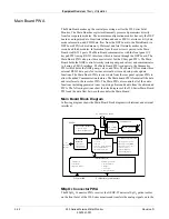
Страница 50: ...the rear panel options PWA to allow the added Communication features The Main board PWA formats all the data and interfaces to the recorder PWA The Main PWA also controls all of the audio functions including generated tones to passing ultrasound audio from the ultrasound PWA The following sections show the block diagram of the 250 Series Main Board PWA and the data flow between the modules the Mai...

Страница 51: ... and volume alarm The main UI keypad has two functions one for input controls and a second for the recorder chart light feature This PWA contains most of the front panel buttons except for the volume and alarm cancel buttons and receives input from the trim knob control The keypad is of the elastomeric type and utilizes backlight LEDs to light each key This PWA also receives the volume alarm keypa...

Страница 52: ...ound PWA generates the ultrasound timing signals to pulse the external patient connected ultrasound transducer crystals and provides the necessary receive circuitry to detect the reflected waveforms It does this by first demodulating the needed signal off of the carrier and filtering the signals which are then sent through the front end motherboard to the DSP where they are digitized and processed...

Страница 53: ...s pulses from the main system PWA and provides the proper drive circuitry to drive the stepper motor 4 phase windings To drive the printhead an adjustable power supply is provided which is set to the printhead specifications each printhead is unique Data to be printed and control information is received from the main system PWA buffered and presented to the printhead Sensors from the recorder asse...

Страница 54: ...2 26 250 Series Maternal Fetal Monitor Revision D 2020551 001 Equipment Overview Theory of Operation ...

Страница 55: ...3 1 250 Series Maternal Fetal Monitor Revision D 2020551 001 3 Installation ...

Страница 56: ...3 2 250 Series Maternal Fetal Monitor Revision D 2020551 001 For your notes ...

Страница 57: ...n indication that the mother has perceived fetal movement The monitor is factory set with the mark configured as an arrow Refer to Install Options Screens on page 3 14 for more information on selecting the mark Refer to the instructions accompanying the Remote Event Marker for more information about using the accessory ECG Out Connector This 3 conductor stereo phone jack permits recording of FECG ...

Страница 58: ...trip chart paper upon commencement of telemetry monitoring and every 30 minutes along with the modes The telemetry disconnected annotation is printed on the strip chart paper if you unplug the telemetry receiver from the 250 Series Monitor you turn off the receiver you turn off the transmitter or the receiver does not detect any active mode information from the transmitter J102 Connector Spectra 4...

Страница 59: ...turation Monitor J109 and J111 only DINAMAP PRO Series 100 400 Monitors DINAMAP ProCare Monitors Quantitative Sentinel Perinatal System any RS 232C connector When shipped from the GE factory all three ports are configured as follows Communications Setup Nellcor baudrate bps 2400 At the above settings connectors J109 and J111 are ready for connection to an NPB Model N 200 Connector J110 does not su...

Страница 60: ...rt is factory set to the Nellcor mode NOTE The Factory mode is reserved for factory testing only Communications Setup Screen Power 1 Ensure the Power switch is in the off O position Turning the Monitor On Off 2 Connect the detachable line cord to the rear panel power connector plug the other end into a hospital grade grounded wall outlet of appropriate voltage If you are unsure about the voltage c...

Страница 61: ...cted At the successful completion of the self test routine the monitor is ready for use Table 7 Monitor Self Test Routines Test Routine Description Display Test All display pixels extinguish for 1 second and then all illuminate for 1 second Afterwards a horizontal line moves across the screen from top to bottom followed by a vertical line moving from left to right Lamp Test The yellow Record indic...

Страница 62: ...ate prior to initial operation of the monitor and during daylight saving time changes A long lasting battery maintains the settings even when the monitor is unplugged from AC power Information on setting the time and date is found in the General Setup screen section in Chapter 4 of the Corometrics 250 Series Monitor Operator s Manual Table 8 Battery Backed RAM Status Icon Appearance Reason Solutio...

Страница 63: ...or the recorder will not print the Record indicator flashes on and off every second three short chimes sound every 3 seconds at a fixed volume of 6 and the message PAPER INCORRECTLY LOADED RELOAD WITH BLACK SQUARES DOWN is displayed overlaying any waveform in the maternal waveform area You may temporarily silence a paper load error condition by pressing the Alarm Silence button The audio alarm wil...

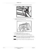
Страница 64: ...er through the recorder 3 Hold the package of paper so that the black squares are on the bottom of the pack and the Corometrics logo and page numbers are on the left side of the pack NOTE The black squares indicate the end of the recorder paper When the black squares appear the strip chart recorder has approximately 20 minutes of paper remaining when running at a speed of 3 cm min NOTE The paper i...

Страница 65: ...is compatible with and required for the 250 Series 4 Unfold two sheets from the top of the package so that they extend toward you 5 Place the pack in the drawer so that the pack is laying flat in the recorder 6 Slowly close the strip chart recorder door being careful not to skew the paper ...

Страница 66: ...splay FECG US US2 Maternal NIBP MSpO2 MHR P Master Alarm General Setup For information on individual setup screens refer to Chapter 5 of the Corometrics 250 Series Monitor Operator s Manual For information on default settings refer to the Table Factory Defaults on page 3 23 Service Mode Screens The 250 Series Monitor is programmed with five service mode screens These screens are listed below Servi...

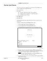
Страница 67: ...1 Select the Setup softkey to display the General screen 2 Select the Service softkey from the General Setup screen 3 The Service Lock screen appears and the access code is displayed as 0 0 0 0 Service Lock Screen 4 The access code is the current month and day MMDD or day and month DDMM however your monitor is configured Use the Trim Knob to enter the access code For example April 23 is 0 4 2 3 28...

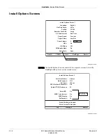
Страница 68: ...Page Language Line Frequency Scaling Paper Speed HR Offset Paper Chime Paper Volume HBC FM Remote Mark Recorder Font Size SpO2 Scale English 60 Hz 30 240 Large 3 cm min Low Out 5 On On Off Auto Only with 259 Model VS Print Interval Real Time Install Options Screen 2 Log PrevPage Restart Fetal Alert Alarm FECG Artifact Elimination Smart BP NIBP 1 min Interval NIBP Display SatSeconds Store Current T...

Страница 69: ...also affected by this setting When the heart rate scale is 30 240 the MSpO2 expanded scale is 60 100 10 cm When the heart rate scale is 50 210 the MSpO2 expanded scale is 50 100 12 5 cm Recorder Font Size The monitor offers a choice of font sizes to print annotations Small increases print speed Medium a compromise between the large and small sizes Large fosters readability VS Print Interval The mo...

Страница 70: ...min On and Off The factory default setting is 10 min What is it When monitoring dual heart rates using US US2 or FECG US overlapping traces may be difficult to interpret All 250 Series Monitors provide a 20 bpm shift for the secondary fetal heart rate trend to alleviate this problem When using US US2 or FECG US2 and the US2 trace is shifted 20 bpm the symbol prints on the upper portion of the top ...

Страница 71: ... at a fixed scale of 0 100 Fetal Alert Alarms If the Spectra Alerts option is installed in your monitor use this field to select between the built in FHR alarm features of the monitor and the Spectra Alerts option Alarms The monitor generates alarms based on the limit settings provided on the FHR setup screens Alerts Enables the Spectra Alerts feature to analyze heart rate and uterine activity dat...

Страница 72: ...ed or loosely connected are recorded when FECG artifact elimination is turned off They are not recorded when FECG artifact elimination is turned on instead gaps pen lift in the tracing occur Default TOCO Reference This field sets the default uterine activity pressure reference for the tocotransducer Use the Trim Knob control to cycle through the available settings 5 10 15 20 or 25 relative units i...

Страница 73: ...iomed may set the SatSeconds limit Off 10 25 50 or 100 to suit the clinical environment and patient condition Default Settings The 250 Series Monitor is shipped with factory defaults for the setup screens You can change most of these settings to suit your particular needs The monitor has two Default Settings that allow you to determine the settings on the next power on or restart Factory or Hospit...

Страница 74: ...f each system setup screen user and service is printed on the strip chart paper The following screen summaries are printed Diagnostic Control Communications Setup Install Options General Setup Master Alarm Setup Vital Signs History MSpO2 Setup MHR P Setup NIBP Setup FECG Setup US Setup US2 Setup NOTE The FECG US and US2 Setup screens are shown together in one group In addition the HR Offset field ...

Страница 75: ...m Knob control to cycle through the available settings 600 1200 2400 4800 9600 and 19 200 bps Each port is factory set to 2400 bps Refer to Peripheral Components on page 2 14 for more information about configuring this field Mode This field selects the mode for communication with an external device Use the Trim Knob control to cycle through the available settings Nellcor Factory Critikon 1371 1371...

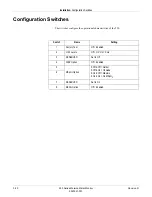
Страница 76: ... switches configure the operational characteristics of the 250 Switch Name Setting 1 Factory Test Off Enabled 2 J102 Levels Off HP On Coro 3 RESERVED Set to Off 4 NIBP Option Off Enabled 5 MSpO2 Option 5 Off 6 Off Nellcor 5 Off 6 On Ohmeda 5 On 6 Off Masimo 5 On 6 On No MSpO2 6 7 RESERVED Set to On 8 MECG Option Off Enabled ...

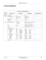
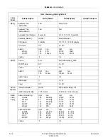
Страница 77: ... 5 1 9 NIBP Initial Target Pressure 135 mmHg 18 0 kPa 100 250 mmHg in increments of 5 13 3 33 3 kPa in 0 7 steps Mode Manual Manual 1 2 3 4 5 10 15 20 30 40 45 60 90 120 min NIBP Done Vol 5 0 9 Alarm mmHg mode Systolic Diastolic MAP MHR P High Low 160 90 mmHg 90 50 mmHg 140 50 mmHg 120 50 bpm High Low 70 240 50 150 70 130 30 120 70 150 30 120 100 250 35 120 Alarm kPa mode Systolic Diastolic MAP MH...

Страница 78: ...h Low 120 50 bpm High Low 100 250 35 120 Alarm Volume 5 1 9 MECG Lead II I II III Pacer Off On Off Normal Operation Waveform Display MECG FECG MECG MSp02 Off MECG Waveform Size 1X 1 mV cm 0 25X 0 5X 1X 2X 4X Auto Master Alarm Setup Alarm Limits mmHg Systolic Diastolic MAP MHR P MSpO2 High Low 160 90mmHg 90 50 mmHg 140 50 mmHg 120 50 bpm 100 95 High Low 70 240 50 150 70 130 30 120 70 150 30 120 100...

Страница 79: ...m min Date Set to current local date Set to current local date Time Set to current local time Must manually change to EST EDT Set to current local time MSpO2 Print Interval External Monitor 5 min Off 2 5 10 15 30 60 min FSpO2 Print Interval External Monitor 5 min Off 2 5 10 15 30 60 min FSpO2 Trace Off Off On Vital Signs History HX Interval Event 1 5 10 15 30 60 Event Table 1 Summary of Factory De...

Страница 80: ... is FHR2 10 min Off On 10 min FM Fetal Movement Remote Marker On On Off SpO2 Scale 0 100 Auto 0 100 Does not change Install Options Screen 2 Service Fetal Alert Alarm Off Off Alarms Alerts Alert Suspend Off Off On Re Alarm MECG and SpO2 only 120 sec 120 300 seconds in 5 second intervals VS Vital Signs Print Interval Real Time Real Time Chart Style Default TOCO Reference 10 in mmHg mode or 1 3 in k...

Страница 81: ...Revision D 250 Series Maternal Fetal Monitor 4 1 2020551 001 4 Maintenance ...

Страница 82: ...4 2 250 Series Maternal Fetal Monitor Revision D 2020551 001 For your notes ...

Страница 83: ... when the monitor operation is suspect FECG UA board voltages annually or when the monitor operation is suspect Printhead adjust remove replace as needed Recorder board photo sensors adjust remove replace as needed Pneumatic pressure check annually Unit to primary leakage as needed Patient to line leakage for ECG as needed Patient to line leakage for IUP as needed Patient to line leakage for MSpO2...

Страница 84: ... Inspect the display face for marks scratches or other damage Physical damage to a flat panel display glass may pose an implosion hazard Have the flat panel display replaced by qualified service personnel if necessary Safety labels and inscription on the device are clearly legible NOTE If an accessory is not listed consult the manufacturer s instructions US2 Measure voltage breakdown Mains to Chas...

Страница 85: ...aning solutions per manufacturers recommendations 2 Wipe off cleaning solutions with a clean dry cloth 3 Do not use a cleaning substance containing wax 4 Do not pour or spray water or any cleaning solution on the equipment or permit fluids to run behind switches into the connectors into the recorder or into any ventilation openings in the equipment 5 Do not use the following cleaning agents Abrasi...

Страница 86: ... transducers from the monitor NOTE Only Nautilus transducers are immersible 1 Dampen a cloth or paper towel with one of the following products then wring out until only slightly wet Sodium Hypochlorite 5 25 Bleach diluted 10 1 Cidex Sporicidin Soap and water 2 Rub soiled area until clean taking care not to excessively wet the tocotransducer diaphragm seal Rub around the seal 3 Dry with a soft dry ...

Страница 87: ...se hoses Do not immerse cuffs without prior application of cuff hose caps Materials Enzymatic detergent such as ENZOL enzymatic detergent US or Cidezyme enzymatic detergent UK Distilled water 10 solution of household bleach 5 25 sodium hypochlorite in distilled water Soft cloths and soft bristled brushes Spray bottles Procedure 1 Prepare the enzymatic detergent according to the manufacturer s inst...

Страница 88: ...heir packaging are damaged they must be disposed of as advised in this appendix To clean or disinfect the sensor 1 Saturate a clean dry gauze pad with the cleaning solution Wipe all surfaces of the sensor and cable with this gauze pad 2 Saturate another clean dry gauze pad with sterile or distilled water Wipe all surfaces of the sensor and cable with this gauze pad 3 Dry the sensor and cable by wi...

Страница 89: ...vel of greater than 10 M ensures that the leakage current is within acceptable levels for safe use on patients 6 Leave transparent dome attached to the transducer during storage but slacken the locking ring at least one quarter of a turn CAUTION STERILIZATION Prior to patient use ensure the dome is sterile Disposal of Product Waste As you use the 250 Series monitor you will accumulate solid wastes...

Страница 90: ...resentatives Electrical Safety Tests Refer to the Preventative Maintenance Inspection Report on page 4 58 for required tools to perform all electrical safety tests in this section IMPORTANT UNITS OF MEASURE The specified leakage tester E278 06 measures in mV There is a direct correlation of mV to µA In other words on this text fixture 1 mV 1 µA 220 230 240 VAC POWER CORD For 220 230 240 VAC testin...

Страница 91: ...ng a Model 129 129F Monitor you must test both FECG and MECG 2 Set the fixture s Leakage switch to Patient 3 Turn ON the monitor using the monitor s power switch 4 Verify the following 50 µA 100 120 220 230 or 240 VAC monitors 5 Record the patient to ground leakage for the following conditions Table 1 Unit to Primary Leakage Conditions Neutral Ground Power Polarity Closed Closed Normal Closed Open...

Страница 92: ... the monitor s front panel UA input The IUP test body can be a SensorTip transducer wrapped in aluminum foil or the assembly leakage cable 2 Set the fixture s Leakage switch to Patient 3 Turn ON the monitor using the monitor s power switch 4 Verify the following 50 µA 100 120 220 230 or 240 VAC monitors 5 Record the patient to ground leakage for the following conditions Table 3 Patient to Line Lea...

Страница 93: ...d Leakage for MSpO2 1 Connect an MSpO2 test body to the monitor s front panel MSpO2 input Use the assembly leakage cable for the test body 2 Set the fixture s Leakage switch to Patient 3 Turn ON the monitor using the monitor s power switch 4 Verify the following 50 µA 100 120 220 230 or 240 VAC monitors 5 Record the patient to ground leakage for the following conditions Table 5 Patient to Line Lea...

Страница 94: ...est body to the monitor s front panel US input The US test body should be an ultrasound transducer wrapped in aluminum foil 2 Set the fixture s Leakage switch to Patient 3 Turn ON the monitor using the monitor s power switch 4 Verify the following 50 µA 100 120 220 230 or 240 VAC monitors 5 Record the patient to ground leakage for the following conditions Table 4 1 Patient to Line Leakage Conditio...

Страница 95: ...ect an US test body to the monitor s front panel US2 input The US test body should be an ultrasound transducer wrapped in aluminum foil 2 Set the fixture s Leakage switch to Patient 3 Turn ON the monitor using the monitor s power switch 4 Verify the following 50 µA 100 120 220 230 or 240 VAC monitors 5 Record the patient to ground leakage for the following conditions Table 4 3 Patient to Line Leak...

Страница 96: ... 5 Record the patient to ground leakage for the following conditions Ground Continuity Use an ohm meter to confirm continuity between the monitor s AC connector inlet ground pin and unit s chassis Dielectric Hi Pot Tests CAUTION POWER OFF Turn off the monitor prior to performing any of the hi pot tests Patient to AC Line Using DC Voltage for 1 Minute Connect the monitor to the hi pot tester as sho...

Страница 97: ... Measure the voltage breakdown F pass F fail MSpO2 Connect an MSpO2 test body to the monitor s front panel MSpO2 input The MSpO2 test body can be an MSpO2 cable and sensor wrapped in aluminum foil or the assembly leakage cable Measure the voltage breakdown F pass F fail US Connect an US test body to the monitor s front panel US input The US test body should be an ultrasound transducer wrapped in a...

Страница 98: ...he monitor s front panel MSpO2 input The MSpO2 test body can be an MSpO2 cable and sensor wrapped in aluminum foil or the assembly leakage cable Measure the voltage breakdown F pass F fail US Connect an US test body to the monitor s front panel US input The US test body should be an ultrasound transducer wrapped in aluminum foil Measure the voltage breakdown F pass F fail 1 2 0 2 4 0 CAUTION FEDER...

Страница 99: ... or patient cables can cause damage which may affect the overall system performance Therefore between factory service visits it is necessary that the proper operation of each monitor be verified by performing the functional checkout procedure described in this section This procedure should be completed prior to initially placing the monitor on a patient when monitor performance needs to be verifie...

Страница 100: ... the power is first turned on verify that two tones are emitted from the rear panel speaker and the green power on indicator is lit 3 Depress the front panel Test button and verify the following All display pixels illuminate for 1 second and then all are extinguished for 1 second Afterwards a horizontal line moves across the screen from top to bottom followed by a vertical line moving from left to...

Страница 101: ...s original on off or maternal only mode state from when the Test button was depressed NOTE To disable the test depress the Test button or open the recorder door NOTE If the simulated fetal heart rate trends do not appear in the correct positions on the strip chart recorder paper ensure the monitor s paper scale 30 240 bpm or 50 210 bpm setting matches the type of paper being used i e 30 bpm cm or ...

Страница 102: ... a rate of 40 cm min by measuring 5 Release the Paper Advance button and verify that the recorder prints the message 1 cm min by measuring 6 Access the Install Options Screen 1 again and follow Steps 3 6 performing the same tests on the other two options 2 cm min and 3 cm min 7 Depress the monitor s front panel Mark Offset button and verify that an event mark is printed on the lowest portion of th...

Страница 103: ...MHR P mode is MECG The MHR heartbeat indicator flashes at a rate of 30 times per minute The UA mode is TOCO 6 Access the Install Options Screen 2 and note the Default TOCO Reference value Exit the service mode by selecting Restart at the bottom of the screen 7 After the monitor restarts press the monitor s front panel UA Reference button 8 Verify the following on the monitor The UA value is refere...

Страница 104: ...of 15 bpm between 110 and 125 bpm on the top grid of the strip chart paper Refer to MECG Oscillation on page 4 25 Repeat Step 13 for rate values of 22 and 27 The results should be the same except that the MHR value alternates between two rates 22 bpm or 27 bpm apart and the recorder prints an oscillation of 22 or 27 bpm The top value is always at approximately 125 bpm Refer to MECG Oscillation on ...

Страница 105: ...Revision D 250 Series Maternal Fetal Monitor 4 25 2020551 001 Maintenance MECG Test 14 Set the simulator s ECG Mode switch to the Off position MECG Ramp MECG Oscillation 15 22 27 ...

Страница 106: ...t a rate of 30 times per minute The UA mode is TOCO 6 Depress and hold the monitor s UA Reference button and release when the UA value shows 10 relative units in mmHg mode or 1 3 kPa in kPa mode Verify the following on the monitor The UA value is referenced to 10 mmHg 1 3 kPa on the display The recorder prints a continuous line at 10 mmHg 1 3 kPa on the bottom grid of the strip chart paper The rec...

Страница 107: ... signal The ECG beep is heard from the rear panel speaker The recorder prints an oscillation of 15 bpm between 110 and 125 bpm on the top grid of the strip chart paper Refer to FECG Artifact Elimination on page 4 29 13 Repeat Step 12 for rates values of 22 and 27 The results should be the same except that the FHR1 value alternates by either 22 or 27 bpm and the recorder prints an oscillation of 22...

Страница 108: ...FHR1 value oscillates by 27 bpm The FHR1 heartbeat indicator flashes for each input signal The ECG beep is heard from the rear panel speaker The recorder does not print any oscillation 18 Access Install Options Screen 2 and set the FECG Artifact Elimination back to Off 19 Set the simulator s ECG Rate switch to the MANUAL position and the Manual Adjustment knob to the counterclockwise position Disc...

Страница 109: ...owing on the monitor The FHR1 value is 120 bpm The FHR1 mode is US The FHR1 heartbeat indicator flashes at a rate of 120 times per minute Ultrasound audio volume from the rear panel speaker can be increased or decreased using the upper left pair of Volume buttons Set the volume to the desired level The recorder prints a continuous line at 120 bpm on the top grid of the strip chart paper The record...

Страница 110: ...itch in each of the individual rate settings 50 60 120 and 210 bpm Verify the following on the monitor The FHR1 value reflects the simulator setting 1 bpm The FHR1 heartbeat indicator flashes at the simulator setting Ultrasound audio is heard coming from the rear panel speaker The recorder prints a continuous line at the respective value 3 bpm on the top grid of the strip chart paper 9 Repeat Step...

Страница 111: ...ulator s Manual Adjustment knob to input an ultrasound signal of approximately 120 bpm Verify the following on the monitor The FHR1 value is 120 bpm The FHR1 mode is US The FMD indication displays in between the FHR1 and FHR2 mode title locations if alerts are not enabled The FHR1 heartbeat indicator flashes at a rate of 120 times per minute Ultrasound audio volume from the rear panel speaker can ...

Страница 112: ...le strain relief and connector pins 2 Disconnect the simulator s ultrasound cable from the front panel of the 250 Series Monitor 3 Connect the ultrasound transducer to either the US or US2 input connector on the front panel of the monitor Verify the following on the monitor The FHR1 value shows three steady dashes The FHR1 mode is US Table 12 Fetal Movement Detection Test Simulator Settings Sectio...

Страница 113: ... of the functional checkout procedure tests the uterine activity section of the 250 Series Monitor 1 Set the switches on the Model 325 Simulator according to Table 13 Uterine Activity Test Simulator Settings on page 4 34 2 Connect the simulator s UA cable to the UA connector on the monitor 3 Access the Install Options Screen 2 and select Pressure units mmHg mode 4 Access the Install Options Screen...

Страница 114: ...f the strip chart paper The recorder prints the messages UA REF on the strip chart paper 10 Place the simulator s UA Level switch at each of the level settings 0 10 50 and 100 mmHg Verify that the UA value is displayed accordingly and that the recorder prints a continuous line at the corresponding value on the uterine activity channel of the strip chart paper 11 Place the simulator s UA Level swit...

Страница 115: ...ly inspect the condition of the cable strain relief and connector pins 2 Connect the tocotransducer to the UA input connector on the front panel of the 250 Series Monitor IMPORTANT TRIMLINE TOCOTRANSDUCER If you are using an older Trimline tocotransducer for this test be advised of the following If the monitor is on when you connect or re connect a Trimline Tocotransducer to the UA connector you m...

Страница 116: ...transducer Visibly assess the condition of the cable strain relief and the connector pins 2 Connect the strain gauge to the UA input connector on the front panel of the 250 Series Monitor Verify the following on the monitor The UA value may read negative numbers indicating baseline pressure is off scale In this case the recorder prints the message BASELINE PRESSURE OFFSCALE on the bottom of the UA...

Страница 117: ...CG US2 IUP MECG NOTE US US2 cannot be tested simultaneously unless two Model 325 Simulators Model 250 Series ultrasound transducers are used Do not attempt to test dual ultrasound using one Model 325 Simulator and one ultrasound transducer or a conflict between enable lines will occur NOTE FECG MECG cannot be tested simultaneously unless two Model 325 Simulators are used NOTE Although dual heart r...

Страница 118: ... the simulator s US cable to the monitor s US input connector 4 Set the switches on the Model 325 Simulator according to Table 14 5 If not already on depress the monitor s Record button 6 Verify the following on the monitor The FHR1 value reads 120 bpm 1 bpm The FHR1 mode reads FECG The FHR1 heartbeat indicator flashes at a rate of 120 times per minute The FHR2 value varies between approximately 5...

Страница 119: ... Series ultrasound transducers Do not attempt to test dual ultrasound using one Model 325 Simulator and one ultrasound transducer This procedure details using two transducers since it is more practical for a test site 2 If not already on depress the monitor s Record button Table 14 Dual Heart Rate Test Non Pattern Simulator Settings Section Switch Setting FECG MECG Rate CMR RATE Rate 120 bpm Mode ...

Страница 120: ...e ultrasound transducer connected to the monitor s US2 input connector try to maintain a steady rate and verify the following on the monitor The FHR2 value responds to the rubbing The FHR2 heartbeat indicator responds to the input The recorder prints the heart rate tracing corresponding to the rate and the trace is bold black Alarm Test This portion of the test ensures the integrity of the audio a...

Страница 121: ...ILENCE X XX message box appears on the screen and a countdown is started 17 Wait the user specified re alarm time and verify the following The alarm tone is once again emitted from the rear panel speaker 18 Use the simulator s Manual Adjustment knob to decrease the MECG rate to 120 bpm Verify the following on the monitor The alarm tone is silenced The MECG value no longer flashes After 10 seconds ...

Страница 122: ...configure as follows Nellcor only Response Time Fast Masimo only Sensitivity Normal Masimo only Averaging 8 Print Interval 2 minutes O2 Trace On 2 Access the monitor s Install Options Screen 1 and set the SpO2 Scale to Auto Select Store Current to Hospital Exit the service mode by selecting Restart at the bottom of the screen 3 Access the monitor s MHR P Setup window and configure as follows MHR P...

Страница 123: ...ng external manometer is recommended The external manometer must be capable of reading to 350 mmHg 46 7 kPa Do not use a DNI CuffLink for calibration procedures on a 250 Series Monitor External Pump Use a hand bulb for all indicated manual inflation activities The external manometer must read pressure in the same scale mmHg or kPa as the monitor Settings can be changed on the monitor Pressure Unit...

Страница 124: ... the Verify softkey has been pressed 5 The monitor will vent pressure to atmosphere and re zero the transducers Calibrate Transducers 1 Select Calibrate from the Mode option 2 The monitor will inflate the cuff to approximately 200 mmHg 26 7 kPa 3 Once the pressure has stabilized enter the pressure from the external manometer in External 4 Best accuracy is achieved if the system is given a short ti...

Страница 125: ... sure you have the 12 foot hose and Normal Adult Cuff tightly wrapped around a rigid 3 inch cylinder This air volume is required to properly test the units leakage rate 2 Monitor will inflate to approximately 200 mmHg 26 7 kPa 3 Following inflation the monitor will allow 45 seconds of settling time 4 Following the settling period two pressure readings are taken 30 seconds apart and used to calcula...

Страница 126: ...nitor top cover Four screws are located on the bottom of the monitor and five screws are located in the back 3 Remove the cover by sliding it toward the rear of the monitor 4 Unplug the display interconnect cable from J2 on the DSP Board 5 Turn on the 250 Series Monitor 6 For making the following measurements on the DSP Board use J2 pin 1 on the for the ground or negative connection 7 Using a digi...

Страница 127: ...e integrity of the ROM RAM Back End Processor and System Voltage levels The module operation begins if no error was detected during the self test Hardware Switches The 250 Series Monitor Main Motherboard contains one dip switch pack SW1 which is used to enable disable a factory test mode for factory use only select between Hewlett Packard or Corometrics compatible outputs from the rear panel J102 ...

Страница 128: ...lays the J102 pin numbers the signal descriptions the range of allowable values for measured voltages the expected output voltages and the settings meaning adjustable using the Trim Knob control Use this screen while verifying and calibrating the digital to analog converters DACs on the Communications Board No 13388 or 15297 1 Access the Diagnostic Control screen by selecting the Service softkey a...

Страница 129: ...rification For each pin select a value in the Meaning field and measure the expected output Analog Ground This field is not adjustable Use J102 pin 3 as a ground when making measurements on other pins HR1 and HR2 Use the Trim Knob control to select 0 bpm or 30 240 bpm in increments of 1 bpm UA Use the Trim Knob control to select from the full range of mmHg or kPa in increments mmHg ranges from 0 1...

Страница 130: ...02 Analog Output Connector Screen J102 Pin Signal Range Voltage Meaning 3 Analog Gnd 0 00 0 0 7 HR1 1 2 1 20 bpm 22 HR2 1 2 1 20 bpm 2 UA 1 2 1 20 0 17 HR1Mode 10 10 00 1 HR2Mode 10 10 00 Test 24 UAMode 10 10 00 20 Markout 0 5 5 Off 18 Chk Paper 0 5 5 Off 14 FMD1 0 5 0 Off 15 FMD2 0 5 0 Off Decimal Exit Table 17 DAC Output Voltages and Adjustment Points for Corometrics Central Station Outputs Anal...

Страница 131: ...ications Setup screen See Communications Screen on page 4 52 2 Insert a loopback test connector into each communications port being tested 3 Set the mode field on the Communications Setup screen to Loopback Notice that the word Off displays to the right of the mode 4 Verify that after a few seconds the status Loopback OK displays OK indicates that the test has passed NOTE If Off remains displayed ...

Страница 132: ...onsidered a performance check and troubleshooting guide to be used in conjunction with other information supplied throughout this service manual It is important to mention this section of the manual is not intended as a substitute for proper professional training or familiarity with the monitor Only qualified service personnel should attempt servicing the 250 Series Monitor Table 19 J109 J110 and ...

Страница 133: ...e Handling Precautions The following guidelines should be followed when handling circuit boards or assemblies containing circuit boards Following these procedures helps resist damage that can be caused by static electricity Discharge any static charge you may have built up before handling parts Wear a grounded anti static wristband at all times Use a static free work surface Store items in anti st...

Страница 134: ...n the FECG UA Board Connect the negative lead to TP2 or TP3 isolated ground Adjust R28 for a reading of 4 00 Vdc 0 01 Vdc Table 20 Main Board Power Supply Voltages 2023111 001 Signal Name Voltage Level Pin 1 12EL 12 Vdc 0 5 Vdc Pin 2 20I 20 Vdc 0 5 Vdc Pin 3 15BP 15 Vdc 0 5 Vdc Pin 4 15V 15 Vdc 0 5 Vdc Pin 5 15V 15 Vdc 0 5 Vdc Pin 6 12A 12 Vdc 0 5 Vdc Pin 7 5V 5 Vdc 0 5 Vdc Pin 8 GND Pin 9 No Conn...

Страница 135: ...load the paper so that black squares show on the surface i e the last several sheets of a pack 8 Turn on the recorder 9 The value on the digital voltmeter should go up and down as the paper surface alternates between black and white Verify that the maximum value is greater than or equal to 2 0 Vdc 10 Turn off the recorder Adjusting the Paper Out Photosensor 1 Load paper in the recorder Ensure that...

Страница 136: ...digital voltmeter connect the positive lead to J9 pin 6 on the Recorder Board connect the negative lead to J9 pin 2 3 Adjust R41 for a reading of 190 mVdc 5 mVdc on the digital voltmeter 4 Although a factory only fixture is required for this step you may wish to try it by estimating the required distance Load paper backwards with the white surface 0 380 in away from the paper tray This creates a p...

Страница 137: ...Revision D 250 Series Maternal Fetal Monitor 4 57 2020551 001 Maintenance Repair Log Repair Log Unit Serial Number Institution Name Date Maintenance Repair Technician Date ...

Страница 138: ...ear and or signs of damage Refer to Visual Inspection on page 4 4 Digital Multimeter Static Free Work Surface Plastic Alignment Tool Mild Soap Water Solution Standard Hand Tools Isopropyl Alcohol Leakage Current Tester Baum Manometer Leg Plate 1590AAO with 1442AAO adapter cable FECG MECG Adapter 1442AAO Model 325 Simulator with Cables Baum Test Connector ESD Mat and Wristband 250 Operator s Manual...

Страница 139: ...ages on the Main Board 4 54 Verify the power supply voltages on the Isolated Power Supply Board 5 9 Adjust the printhead 4 55 Adjust the photosensors on the Recorder Board Electrical Safety Tests Page Description Complete Max Actual Pass Fail N A 4 10 AC Line 120 V 10 300 mW 4 10 Ground Impedance 300 MΩ Lead to rear panel ground lug 300 MΩ Lead to top cover bezel screw 300 MΩ 300 mW 4 10 Unit to p...

Страница 140: ...Pass Fail N A 5 3 Monitor Self Test 4 22 Front Panel Button Test 4 23 MECG Test 4 26 FECG Test Leg Plate Test Follow Manufacturer s Directions 4 29 Ultrasound Test 4 31 Fetal Movement Detection Test 4 32 Ultrasound Test 4 33 Uterine Activity Test 4 35 Tocotransducer Test 4 36 Strain Gauge Test if used 4 37 Pattern Memory Test 4 38 Dual Heart Rate Test 4 49 Dual Ultra Sound Modes 4 40 Alarm Test 4 ...

Страница 141: ...Revision D 250 Series Maternal Fetal Monitor 4 61 2020551 001 Maintenance Preventative Maintenance Inspection Report Comments ...

Страница 142: ...4 62 250 Series Maternal Fetal Monitor Revision D 2020551 001 Maintenance Preventative Maintenance Inspection Report ...

Страница 143: ...Revision D 250 Series Maternal Fetal Monitor 5 1 2020551 001 5 Troubleshooting ...

Страница 144: ...5 2 250 Series Maternal Fetal Monitor Revision D 2020551 001 For your notes ...

Страница 145: ...problem on the DSP Board If the monitor displays any of these messages turn off the monitor and contact your GE Service Representative Monitor Self Test The 250 Series Monitor contains self test routines which verify the unit s calibration and internal circuitry These routines are initiated by depressing the front panel Test button The test results are printed on the strip chart recorder paper ver...

Страница 146: ...e Install Options Screen 1 displays a Select NextPage b The Install Options Screen 2 displays 4 Select the Log softkey from the Install Options Screen 2 5 The first Event Log screen displays 6 Use the Page softkey to display the next screen page if applicable The last page wraps back to the first page 7 Use the Print softkey to print the displayed screen page on the strip chart recorder 8 Use the ...

Страница 147: ...rse Call Interface relay CPU software version number DSP software version number Monitor Run Time Recorder run time Rec Time Clear softkey sets run time and record to 0 00 Main Board SW1 switch setting summary Softkey to access J102 test screen and Softkey to access the NIBP Calibration screen Diagnostic Control J102 Exit Diagnostic Control Recorder Calibration Off Status Relay Off NIBP Cal CPU V4...

Страница 148: ...m for domestic paper 50 bpm and 210 bpm for international paper The recorder prints a vertical line spanning across both grids every 3 16 inch Refer to figure below 2 Use this test while performing the adjustments in Recorder Servicing on page 5 7 The test will continue to print the lines until you cycle power on the monitor or set the calibration field on the Diagnostic Control screen back to Off...

Страница 149: ...ill avoid unnecessary damage to bezel s mounting screws and the unit s front panel connectors 1 Turn off the 250 Series Monitor and disconnect the power cord from the monitor 2 Remove the nine screws which secure the monitor top cover Four screws are located on the bottom of the monitor and five screws are located in the back 3 Remove the cover by sliding it toward the rear of the monitor 4 Remove...

Страница 150: ...gauges and fixtures to ensure critical tolerances are satisfied this includes drive roller assemblies Therefore field replacement is not recommended and field servicing is limited to the following recorder subassemblies Stepper Motor and Harness Printhead Paper Low Photosensor Paper Out Photosensor Paper Loading Photosensor CAUTION PRINTHEAD FAILURE If a sudden or complete failure of the printhead...

Страница 151: ...et Adjustment To check vertical offset alignment run at least two monitor self tests by depressing the front panel Test button The first horizontal trace should be printed 0 490 0 002 inch from the right hand paper guide Refer to figure Vertical Offset Adjustment Self Test Trace on page 5 13 Perform the following steps if the trace does not fall within the specified offset range 1 Loosen the two s...

Страница 152: ...you have a short screwdriver you will not need to remove the strip chart recorder from the monitor 1 Turn off the 250 Series Monitor and disconnect the power cord from the monitor 2 Remove the nine screws which secure the monitor top cover Four screws are located on the bottom of the monitor and five screws are located in the back 3 Remove the cover by sliding it toward the rear of the monitor 4 D...

Страница 153: ... is the VHEAD voltage The voltage rating should be marked over the old voltage rating on the printhead bracket 3 Re connect the harness cable to the printhead 4 Slide the new printhead into position through the recorder door and under its bracket Push on the center of the printhead to ensure it is pushed all the way back 5 Align the printhead with the front holes in the bracket and replace the two...

Страница 154: ...5 12 250 Series Maternal Fetal Monitor Revision D 2020551 001 Troubleshooting Diagnostic Control Screen Recorder Top View Recorder Right Side View J6 J5 J3 J4 J1 J2 J8 A D E A B C ...

Страница 155: ... following procedure NOTE When facing the front of the monitor the paper low sensor is on the right side the paper out sensor is on the left side Removing the Paper Low Paper Out Photosensor Use the following procedure for removing the paper low or paper out photosensor 1 Turn off the 250 Series Monitor and disconnect the power cord from the monitor 2 Remove the nine screws which secure the monito...

Страница 156: ...usting the Paper Low Photosensor Refer to Recorder Photosensor Calibration on page 4 55 for detailed instructions Adjusting the Paper Out Photosensor Refer to Recorder Photosensor Calibration on page 4 55 for detailed instructions Paper Loading Sensor Follow the instructions for Recorder Servicing on page 5 7 before following this procedure Removing the Paper Loading Photosensor 1 Disconnect the p...

Страница 157: ... recorder door is opened the cable does not become taut Re install the strip chart recorder Refer to Installing the Strip Chart Recorder on page 5 7 Do not replace the monitor top cover yet 5 Adjust the paper loading sensor as described next in this section Adjusting the Paper Loading Sensor Refer to Recorder Photosensor Calibration on page 4 55 for detailed instructions ...

Страница 158: ...In the center of the screen are four single digit fields below the field Enter Access Code These fields are used to enter the code to access restricted service settings in the 250 Series Monitors The access code is the current date setting in the form of M M D D or D D M M where M M is the current month 01 to 12 and D D is the current date 01 through 31 however your monitor is configured NOTE The ...

Страница 159: ... Off NOTE The software does not permit the alarm settings to overlap 8 To exit the Service mode follow the instructions at the top of Page 16 How do I change the alarm limits for Fetal Heart Rate 2 1 Rotate the Trim Knob to highlight the field for FHR2 This field is at the top left on the display and it may read INOP or US2 2 Once you highlight the FHR2 field press the Trim Knob The display change...

Страница 160: ...nge the MHR P Maternal Heart Rate Pulse High select a value between 100 bpm and 250 bpm NOTE The MHR P alarm settings are also available through the Pulse softkey or the MSpO2 softkey on the main monitoring screen You may optionally change the MHR P Low select a value between 35 bpm and 120 bpm NOTE The MHR P alarm settings are also available via the Pulse softkey or the MSpO2 softkey on the main ...

Страница 161: ...MHR P Setup screen 3 Now rotate the Trim Knob to highlight the Source setting It will read Auto MSpO2 MECG 4 Once the Source setting is highlighted press the Trim Knob again The current setting displays in blinking inverse video 5 Now rotate the Trim Knob to change the current setting Select from Auto MSpO2 MECG If you select Auto the pulse value parameter is automatically selected according to th...

Страница 162: ... Scale setting is highlighted press the Trim Knob again The current setting displays in blinking inverse video 8 Now rotate the Trim Knob to change the current setting Select a setting of 0 100 or Auto 9 Once you set the desired trace setting press the Trim Knob again to confirm The current setting stops blinking 10 To exit the Service mode follow the instructions at the top of Page 16 How do I ch...

Страница 163: ...g inverse video 5 Now rotate the Trim Knob to change the current setting to MECG 6 Once you set the desired source parameter press the Trim Knob again to save the value The current value setting stops blinking 7 Now rotate the Trim Knob to select highlight the MECG Lead setting This setting is slightly above vertical center towards the right side of the screen and indicates Lead I II or III 8 Now ...

Страница 164: ...e press the Trim Knob to confirm your selection The current value setting stops blinking and the waveform should reflect the selected lead How do I disable enable Fetal Movement Detection FMD is an optional feature that is purchased separately 1 Rotate the Trim Knob to highlight the field for US This field is top left on the display NOTE This feature applies only if ultrasound is the source 2 Once...

Страница 165: ... audio tone indicative of the alarm volume is emitted from the speaker 11 To exit the Service mode follow the instructions at the top of Page 16 How do I enable or change alarm volume settings for Fetal Heart Rate 2 1 Rotate the Trim Knob to highlight the field for FHR2 This field is top left on the display and may display as INOP or US2 2 Once the FHR2 field is highlighted press the Trim Knob The...

Страница 166: ...mediately to the right The setting is in the range of 1 to 9 4 Once the Alarm Volume setting is highlighted press the Trim Knob again The current setting displays in blinking inverse video and an audio tone indicative of the alarm volume is emitted from the speaker 5 Now rotate the Trim Knob to change the current setting as desired With each setting change an audio tone indicative of the alarm vol...

Страница 167: ...nfirm your selection The current value setting stops blinking 7 To exit the Service mode follow the instructions at the top of Page 16 How do I change the volume for FHR2 audio or heart beat tones Option 1 1 Use the front panel Volume Up or Volume Down buttons right to control volume for FHR Channel 2 Option 2 1 Rotate the Trim Knob to highlight the field for FHR2 This field is top left on the dis...

Страница 168: ...on The current value setting stops blinking 7 To exit the Service mode follow the instructions on Page 16 How do I change the volume for NIBP completion indication 1 Rotate the Trim Knob to highlight the field for NIBP This field is slightly above center on the left side of the display 2 Once the NIBP field is highlighted press the Trim Knob The display changes to show the NIBP Setup screen 3 In t...

Страница 169: ...rrent to Hospital automatically sets the Default Settings to Hospital How do I set change RS232 serial communications baudrates and protocols 1 Enter Install Options Screen 1 Refer to How do I access the service setup install options screens on page 5 27 2 In Install Options Screen 1 rotate the Trim Knob to highlight the COMM softkey at the bottom of the display below the menu bar 3 Press the Trim...

Страница 170: ...nce the HBC setting is highlighted press the Trim Knob again The current setting displays in blinking inverse video 5 Now rotate the Trim Knob to change the current volume setting Select a value 6 Once you set the desired value press the Trim Knob again to save the value The current value setting stops blinking 7 To exit the Service mode follow the instructions at the top of Page 16 How do I chang...

Страница 171: ...uto 60 min Auto 90 min or Auto 120 min 6 Once you set the desired alarm value press the Trim Knob to confirm your selection The current value setting stops blinking 7 To exit the Service mode follow the instructions at the top of Page 16 How do I change the display time out duration for Non Invasive Blood Pressures 1 Navigate to Install Options Screen 2 2 Now rotate the Trim Knob to highlight the ...

Страница 172: ...day DD month MMM and year YYYY 5 After the desired field is highlighted selected press the Trim Knob The current setting displays in blinking inverse video 6 Now rotate the Trim Knob to change the current date parameter setting 7 Once you set the desired value press the Trim Knob again to save the value The current value setting stops blinking 8 Repeat Step 4 through Step 7 for any other date para...

Страница 173: ...ecorder completely From the On or MATERNAL ONLY state The yellow LED above the recorder is illuminated or flashing intermittently press the Record button and hold for 2 seconds until the monitor emits a two tone audio beep which indicates that the recorder is off The yellow LED is now extinguished How do I change the LOW PAPER NO PAPER alarm conditions 1 Enter the Install Options Screen 1 Rotate t...

Страница 174: ... to highlight the J102 softkey at the bottom of the display below the menu bar This opens the J102 screen The J102 connector is where HR and UA parameters are available as analog voltages at the rear panel of your monitor 4 The J102 screen is divided into five columns Pin Signal Range Voltage and Meaning Pin refers to the physical pinout of the connector Signal is the signal schematic designation ...

Страница 175: ... the setting to On and press the Trim Knob again 6 The recorder should now begin to print two distinct calibration mechanisms Continuous calibration lines at the upper and lower limits of the heart rate and uterine activity scales This is to aid in the alignment of the print head assembly Approximately every 3 16 in a full line will print from end to end This is to test all print head elements and...

Страница 176: ...he Trim Knob to highlight the desired baudrate selection on the desired communication port line 7 Press the Trim Knob The current setting displays in blinking inverse video 8 Now rotate the Trim Knob to change the current baudrate setting Select from one of the following 600 1200 2400 4800 9600 and 19200 9 When the desired test baudrate displays press the Trim Knob again to save The current value ...

Страница 177: ...Options Screen 1 256 and 259 models Install Options Screen 2 256 and 259 models Communications Setup 256 and 259 models Diagnostic Control 256 and 259 models 6 Wait until the printer stops and the display returns to the Install Options Screen 1 before you exit the Service mode 7 To exit the Service mode following the instructions at the top of Page 16 I have made the monitor configuration changes ...

Страница 178: ...h is open Off and the associated signal is enabled A 0 indicates the switch is closed On and the associated signal is disabled 4 The eight switches are defined as in the following table 5 On the line immediately below the dip switch settings the current configuration is interpreted as text information For instance when the dip switch settings indicate 11101100 the configuration line will read MECG...

Страница 179: ...fected If you are unable to find anything obvious or you are unable to verify the reported problem follow the step by step 250 SERIES SERVICE TROUBLE SHOOTING PROBLEM SUBASSEMBLY COMMENTS VIDEO COMM BOARD WITH I O CONNECTORS Sits on same data bus as DSP Display board SYSTEM POWER SUPPLY INVERTOR If display is very dim INVERTOR TO LCD PANEL CABLE If display is very dim DSP TO INVERTOR CABLE Video g...

Страница 180: ...s on same data bus as DSP Display board FAN Secondary failure due to overheating only FECG FECG FRONT END CABLE CONNECTOR Usually Bad Connector Crimps ISOLATED POWER SUPPLY FRONT END MOTHERBOARD Passes all front end signals make sure boards seated no connector damage FECG UA BOARD DSP BOARD Processes FECG analog SYSTEM POWER SUPPLY MAIN BOARD Processes for display COMM BOARD WITH I O CONNECTORS Si...

Страница 181: ...ing FECG UA BOARD Can affect board try removing SYSTEM POWER SUPPLY COMM BOARD WITH I O CONNECTORS Sits on same data bus as DSP Display board FAN Secondary failure due to overheating only MSpO2 MSpO2 FRONT PANEL CONNECTOR BOARD More likely internal cable MSpO2 MODULE FRONT END MOTHERBOARD Passes all front end signals make sure boards seated no connector damage ISOLATED POWER SUPPLY MSpO2 FRONT END...

Страница 182: ...d on US board FRONT END MOTHERBOARD Passes all front end signals make sure boards seated no connector damage SYSTEM POWER SUPPLY MAIN BOARD Processes for display COMM BOARD WITH I O CONNECTORS Sits on same data bus as DSP Display board FAN Secondary failure due to overheating only ULTRASOUND 2 ULTRASOUND BOARD If US1 heart rate is displayed on US2 cables swapped on US board DSP BOARD Processes US2...

Страница 183: ...if main boards thinks door is open RECORDER BOARD TO DOOR SWITCH CABLE Will not print if main boards thinks door is open SYSTEM POWER SUPPLY UI KEYPAD BOARD Would effect all buttons on front panel FAN Secondary failure due to overheating only PAPER ADVANCE DSP TO UI KEYPAD CABLE Affects all front panel functions RECORDER MOTOR Could have open winding or bad wire crimp in connector UI KEYPAD BOARD ...

Страница 184: ...ing only RECORDER BUTTON RECORDER ON RECORDER BOARD TO MAIN BOARD CABLE UI KEYPAD BOARD Would affect all buttons on front panel RECORDER BOARD Drives the stepper motor DSP TO UI KEYPAD CABLE Affects all front panel functions RECORDER MOTOR Could have open winding or bad wire crimp in connector DOOR SWITCH Will not print if main boards thinks door is open MAIN BOARD Communicates with keypad SYSTEM ...

Страница 185: ...R MOTOR Could have open winding or bad wire crimp in connector MAIN BOARD Communicates with keypad SYSTEM POWER SUPPLY DOOR SWITCH Will not print if main boards thinks door is open DSP BOARD Front panel keypad routed through DSP board FAN Secondary failure due to overheating only CHART LIGHT UI KEYPAD BOARD Would affect all buttons on front panel DSP TO UI KEYPAD CABLE Affects all front panel func...

Страница 186: ...oses Affects all front panel functions To front panel Pneumatics to main DSP TO UI KEYPAD CABLE Affects all front panel functions UI KEYPAD BOARD Would affect all buttons on front panel PNEUMATICS BOARD PUMP VALVES Pump valves hoses MAIN BOARD Communicates with keypad SYSTEM POWER SUPPLY DSP BOARD Front panel keypad routed through DSP board FAN Secondary failure due to overheating only MARK OFFSET...

Страница 187: ...RECORDER BOARD Sensor Voltage Adjustment Drift RECORDER BOARD TO PAPER OUT SENSOR RECORDER BOARD TO MAIN BOARD CABLE MAIN BOARD FAN Secondary failure due to overheating only PAPER MISLOAD RECORDER BOARD TO PAPER MIS LOAD CABLE RECORDER BOARD Sensor Voltage Adjustment Drift RECORDER BOARD TO MAIN BOARD CABLE MAIN BOARD Processes this status from recorder board FAN Secondary failure due to overheati...

Страница 188: ... and off every second Recorder does not function the Record indicator is off the message PAPER INCORRECTLY LOADED RELOAD WITH BLACK SQUARES DOWN is shown in maternal waveform area Recorder does not function and the Record indicator is on Recorder is off out of paper or paper is incorrectly loaded Recorder is in maternal only mode Paper supply is low Paper loaded backwards Service required Press Re...

Страница 189: ...monitoring mode Replace transducer Rate on FHR area of display and FHR trend on strip chart paper do not correlate Paper Scale is incorrectly configured to either 50 210 bpm or 30 240 bpm Call Biomedical Engineering Department Table 24 FECG Troubleshooting Problem Probable Cause Possible Solution Internal FECG erratic or not recording properly Transducer not properly connected to monitor Attachmen...

Страница 190: ...Reference button while no pressure is applied to transducer button Re apply transducer Do not overtighten belt Press UA Reference button again between contractions Flashing sign Relative pressure 100 Press the UA Reference button between contractions CHECK TOCO message is shown in UA area of the display area when the UA Reference button is pressed UA Reference button pressed before UA circuits sta...

Страница 191: ...etus pressing directly on catheter Defective strain gauge or catheter Service required Flush catheter Re zero Replace catheter if necessary Reposition by twisting catheter Replace strain gauge or catheter Call Biomedical Engineering Department Table 27 MECG Troubleshooting Problem Probable cause Possible solution MECG erratic or not functioning properly Patient cable not properly connected to moni...

Страница 192: ...BP area of display Cuff pressure has exceeded the overpressure limit of 315 mmHg 15 mmHg Kinked hose Blocked hose Restrict patient limb movement If this is not the case contact Biomedical Engineering Department Check the external cuff for kinks Perform pneumatic test COMM message displayed in NIBP area of display Communication error between the built in NIBP module and the remainder of the monitor...

Страница 193: ...sor Excessive maternal movement Excessive ambient light Damaged sensor Check patient The patient may be experiencing shock hypotension severe vasoconstriction severe anemia hypothermia arterial occlusion proximal to the sensor or cardiac arrest Ensure that the intermediate cable is firmly attached to the monitor and to the sensor assembly Ensure sensor is not too tight Move sensor to another locat...

Страница 194: ...5 52 250 Series Maternal Fetal Monitor Revision D 2020551 001 Troubleshooting General Troubleshooting ...

Страница 195: ...Revision D 250 Series Maternal Fetal Monitor 6 1 2020551 001 6 Parts List Drawings and Replacement ...

Страница 196: ...6 2 250 Series Maternal Fetal Monitor Revision D 2020551 001 For your notes ...

Страница 197: ...r in special cases involving field installed upgrades the revision level of a diagram or parts list in this manual may not reflect the revision level of your unit s subassemblies When discrepancies are found contact your GE Medical Systems Information Technologies Service Representative NOTE Fab drawings are not contained in this manual Service Parts WARNING REPAIR TO THE FRU LEVEL Field repairs a...

Страница 198: ...not include front end patient cables 4 N A 2025177 003 Speaker FRU 4 3 2025177 005 DSP Board FRU 4 6 2025177 007 Dual Ultrasound Board FRU 4 7 2025177 008 FECG UA w MECG Board FRU 4 7 2025177 009 Isolated Power Supply Board FRU 4 9 2025177 010 SpO2 Carrier Board w Nellcor Ox FRU 4 9 2025177 011 SpO2 Carrier Board w Masimo Ox FRU 4 9 2025177 012 SpO2 carrier Board w Ohmeda Ox FRU 4 N A 2025177 020 ...

Страница 199: ... of warranty may purchase 9 2 4 2025177 023 Keypad Volume Pad FRU 9 7 8 2025177 026 Trim Knob and Switch 10 1 2025177 017 Recorder Assembly w o Mnt Brkt FRU 11 25 2025177 018 Recorder Board FRU N A N A 2025177 002 Hardware Kit FRU Screws washers spacers for full monitor N A N A 2025177 031 Top Cover Gasket FRU Refer to Caution on page 6 30 Serv Manual Drawing Page Number Bubble Number Part Number ...

Страница 200: ...lowing FRU Main Reference Guide drawing The numbers in the bubbles coincide with the last three digits of the part number listed in the FRU list e g 020 represents FRU P N 2025177 020 To order Miscellaneous Cables HARDWARE KIT To order mounting hardware 016 003 005 020 018 017 021 023 026 022 024 025 027 013 014 028 006 004 030 English International 024 025 English International Card Cage ...

Страница 201: ...0 Series Maternal Fetal Monitor 6 7 2020551 001 Parts List Drawings and Replacement Field Replaceable Units FRUs 010 029 007 009 011 012 008 SpO2 Carrier Bd w Nellcor SpO2 Carrier Bd w Masimo SpO2 Carrier Bd w Datex ...

Страница 202: ...0 conductor DSP to LCD Decoder ribbon cable from DSP board connector J2 4 Disconnect 10 conductor DSP to Keypad ribbon cable from DSP board connector J5 5 Remove two screws fixing DSP board to chassis Keep screws aside 6 Remove DSP board from Main board 7 Remove two screws fastening Pneumatics assembly to chassis 8 Remove Pneumatics assembly Leave tubing connected to Front Bezel The tubing length ...

Страница 203: ... connector J5 30 Place DSP board onto Main board Use two screws to fasten DSP board to chassis 31 Replace top cover Re insert screws 2025177 005 DSP Board 1 Remove top cover Keep screws aside 2 Disconnect 8 conductor Inverter cable from DSP board connector J1 3 Disconnect 20 conductor DSP to LCD Decoder ribbon cable from DSP board connector J2 4 Disconnect 10 conductor DSP to Keypad ribbon cable f...

Страница 204: ...onnector on Main board 17 Connect power switch cable to front bezel power switch chassis mounted connector 18 Adhere new cable tie mount to side of chassis 19 Use tie wrap to fasten power switch cable to cable tie mount on chassis 20 Replace top cover Re insert screws 21 Set the voltage selector switch located on the rear panel to the appropriate voltage 2025177 007 Dual Ultrasound Board 1 Remove ...

Страница 205: ...tor 8 Remove MECG if installed and FECG board from Front end Motherboard 9 If MECG is installed Remove two screws fastening MECG board to FECG board 10 If MECG is installed Remove MECG board from FECG board 11 If MECG is installed Insert MECG board onto new FECG board and fasten with two screws 12 Insert MECG if installed and new FECG board into Front End Motherboard 13 If MECG is installed Connec...

Страница 206: ...able from DSP board connector J1 5 Disconnect 20 conductor DSP to LCD Decoder ribbon cable from DSP board connector J2 6 Remove card cage cover Keep screws aside 7 Disconnect MSpO2 cable from SpO2 Carrier board connector 8 Remove SpO2 Carrier board with Nellcor MSpO2 Module assembly from Front end Motherboard 9 Insert new SpO2 Carrier board with Nellcor MSpO2 Module assembly into Front End Motherb...

Страница 207: ... 15 Place top cover Re insert screws 2025177 012 SpO2 Carrier Board with TruSignal MSpO2 Module 1 Remove top cover Keep screws aside 2 Remove two screws fastening DSP board to chassis 3 Remove DSP board from Main board 4 Disconnect 8 conductor Inverter cable from DSP board connector J1 5 Disconnect 20 conductor DSP to LCD Decoder ribbon cable from DSP board connector J2 6 Remove card cage cover Ke...

Страница 208: ...al sheets from Front end Motherboard 15 Remove five screws fastening the Front end Motherboard to the chassis 16 Remove two screws on both sides of monitor fastening the front bezel to the chassis 17 Tilt the front bezel forward away from the chassis 18 Remove MSpO2 cable beads from chassis bead clips 19 Remove MECG and FECG cable beads from chassis bead clips 20 Remove FECG ground cable from chas...

Страница 209: ...DSP board to chassis Keep screws aside 3 Remove DSP board from Main board 4 Disconnect 8 conductor Inverter cable from DSP board connector J1 5 Disconnect 20 conductor DSP to LCD Decoder ribbon cable from DSP board connector J2 6 Disconnect 10 conductor DSP to Keypad ribbon cable from DSP board connector J5 7 Remove one flat head screw from each side of the monitor fastening the front bezel to cha...

Страница 210: ...assis 33 Remove Recorder assembly and mounting bracket 34 Remove two screws fastening Pneumatics assembly to chassis 35 Disconnect clear tubing from both PT1 and PT2 on the Main board 36 Remove Pneumatics assembly from the Main board 37 Remove four screws fastening the Comm Board to the chassis 38 Remove Comm board from Main board 39 Disconnect power supply cable from Main board connector J8 40 Di...

Страница 211: ...ssis grommet towards Front bezel 70 Fasten Recorder assembly and mounting bracket to chassis with four M3 5x6 screws 71 Connect Recorder EMC ground wire Fast on tab to chassis 72 Connect power supply cable to J1 connector on Recorder board 73 Connect 20 conductor Recorder ribbon cable to Main board connector J9 74 Slide new Front end Motherboard under card cage onto chassis 75 Fasten to chassis wi...

Страница 212: ...DSP board onto Main board Use two screws to fasten DSP board to chassis 99 Slide on top cover Re insert screws 2025177 016 COMM Board 1 Remove top cover Keep screws aside 2 Remove four screws fastening the Comm Board to the chassis 3 Remove Comm board from Main board 4 Place new Comm board onto Main board 5 Fasten Comm board onto chassis with four screws 6 Replace top cover Re insert screws 202517...

Страница 213: ...t power supply cable to J1 connector on Recorder board 5 Connect 20 conductor Recorder ribbon cable to Recorder board connector J2 6 Open Recorder door as it will interfere with front bezel attachment 7 Tilt the front bezel back onto chassis Ensure that two front bezel fiducial pins are aligned with Recorder slots Ensure that three tabs on the bottom of front bezel are aligned with chassis slots S...

Страница 214: ... Board 1 Fasten new Recorder board to Recorder assembly with one screw 2 Connect Recorder print head cable to Recorder board connector J3 3 Connect Recorder paper orientation sensor cable to Recorder board connector J8 4 Connect two Recorder optical sensor cables to Recorder board connectors J5 and J6 5 Connect Recorder EMC ground wire Fast on connector to chassis tab 6 Connect power supply cable ...

Страница 215: ...ng Use either end of the cable The connector is keyed and will only mate the correct way 13 Using needle nose pliers disconnect 8 conductor Inverter cable from the opening in the side of the Display assembly 14 Connect replacement cable to Inverter board through Display assembly opening Use either end of the cable The connector is keyed and will only mate the correct way 15 Disconnect 10 conductor...

Страница 216: ...Pull red tubes through chassis grommet away from Front bezel 12 Remove two screws fastening Pneumatics assembly to chassis Keep screws aside 13 Disconnect clear tubing from both PT1 and PT2 on the Main board 14 Remove Pneumatics assembly from the Main board 15 Replace new Pneumatics assembly onto Main board 16 Replace two screws fixing Pneumatics assembly onto chassis 17 Connect clear section of t...

Страница 217: ...ew fastening Display mounting bracket to front bezel 12 Remove screw fastening bracket to Display assembly 13 Remove four screws fastening Display assembly to front bezel 14 Remove Display assembly 15 Remove Display lens 16 Insert new Display lens 17 Insert new Display assembly Fasten to front bezel with screws 18 Fasten bracket to Display assembly with screw 19 Fasten bracket to front bezel with ...

Страница 218: ...assis post by removing nut 16 Disconnect FECG cable from Front end Motherboard 17 Disconnect IUP cable from Front end Motherboard 18 Disconnect two red Pneumatics tubes from Front bezel NIBP connector 19 Disconnect 10 conductor Keypad to Volume ribbon cable from Volume board connector 20 Remove screw fastening Display mounting bracket to front bezel 21 Remove screw fastening bracket to Display ass...

Страница 219: ...Fasten bracket to front bezel with screw 52 Connect 10 conductor Keypad to Volume ribbon cable to Volume board connector 53 Connect red tubes to Front bezel NIBP connector 54 Connect IUP cable to Front end Motherboard 55 Connect FECG cable to Front end Motherboard 56 Place FECG ground cable onto chassis post and tighten with nut 57 Insert MECG and FECG cable beads into chassis bead clips 58 Insert...

Страница 220: ...me board and side keyboard pad to front bezel 13 Remove Volume board and side keyboard pad 14 Disconnect Encoder cable from Keypad board 15 Remove two screws fastening Keypad bracket to front bezel 16 Remove Keypad bracket 17 Remove four screws fastening Keypad to front bezel 18 Remove Keypad board and main keyboard pad 19 Insert new Keypad board and main keyboard pad into front bezel 20 Fasten Ke...

Страница 221: ...onnect 10 conductor Keypad to Volume ribbon cable from Volume board connector 10 Disconnect Encoder cable from Keypad board 11 Remove Trim Knob Encoder washer and Encoder 12 Insert new Encoder Encoder washer and Trim Knob 13 Connect Encoder cable to Keypad board 14 Fasten Keypad bracket to front bezel with two screws 15 Insert new Volume board and side keyboard pad into front bezel 16 Fasten Volum...

Страница 222: ...witch 12 Push power switch out through front bezel 13 Connect power switch cable to power supply bulkhead mounted connector 14 Push power switch in through front bezel 15 Insert metal retaining clip into top and bottom bridges on power switch Then push in tightly 16 Connect four Fast on tab connectors to power switch 17 Tilt the front bezel back onto chassis Refasten screws to each side of chassis...

Страница 223: ...head screws from side of Power Supply See photograph below 17 Remove four pan head screws from back of Power Supply 18 Remove one pan head screw from inside bottom of Power Supply See photograph below 19 Unplug Fan from Power Supply 20 Remove Power Supply from chassis 21 Replace with new Power Supply 22 Fasten three flat head screws into side of Power Supply 23 Fasten four pan head screws into bac...

Страница 224: ... 9 Remove two screws fastening MECG board to FECG board 10 Remove MECG board from FECG board 11 Insert new MECG board onto FECG board and fasten with two screws 12 Insert MECG and FECG boards into Front End Motherboard 13 Connect MECG cable to MECG board connector 14 Replace card cage cover Re insert screws 15 Reconnect 8 conductor Inverter cable to DSP board connector J1 16 Reconnect 20 conductor...

Страница 225: ...gasket protects the inside of the unit from fluid spills Whenever the monitor cover is removed during servicing be sure to inspect the gasket ensuring it is attached securely across the whole front of the top cover along the stamping line just in from the edge If the adhesive is no longer effective order replacement Top Cover Gasket FRU 2025177 031 ...

Страница 226: ...6 32 250 Series Maternal Fetal Monitor Revision D 2020551 001 Parts List Drawings and Replacement Assembly Disassembly of FRUs ...

Страница 227: ...Revision D 250 Series Maternal Fetal Monitor A 1 2020551 001 A Technical Specifications This section contains a detailed list of the technical specifications for the 250 Series Monitor ...

Страница 228: ...A 2 250 Series Maternal Fetal Monitor Revision D 2020551 001 Technical Specifications For your notes ...

Страница 229: ...50 F to 104 F 10 C to 40 C 80 F 26 5 C 30 to 70 non condensing 45 to 65 non condensing 700 1060 mbar 525 795 mmHg 700 1060 mbar 525 795 mmHg Certification ANSI AAMI EC13 1992 UL 2601 1 CUL Complies with all areas except those listed below 3 1 2 1e Heart Rate Meter Accuracy and Response to Irregular Rhythm not tested 3 2 6 1 Range of QRS wave amplitude and duration 3 2 7 Range and accuracy of heart...

Страница 230: ...able 110 dB at mains frequency 10 µV peak to peak 10 MΩ 20 MΩ 40 dB 60 µA at 254 VAC electrically isolated 4 kVAC Ultrasound Mode Technique Transducer Type Pulse Repetition Frequency Single Ultrasound Mode Dual Ultrasound Mode Pulse Duration Transmitter Frequency Spatial Peak Temporal Average Intensity Spatial Average Temporal Average Intensity Focal 20 dB Beam Area Peak Instantaneous Intensity Pe...

Страница 231: ...al Tachycardia Response Time Peak detecting beat to beat cardiotachometer Medtronic 1700 003 or equivalent I II and III 30 240 bpm 1 bpm 1 second average 1 update per second 0 5 mV to 5 mV peak to peak 0 5 mV RTI 0 8 x QRS amplitude 2 seconds 3 seconds 10 seconds high alarm limit at 100 bpm 300 mVdc maximum 20 V peak to peak 0 6 to 40 Hz 80 dB at mains frequency with patient cable 50 dB at mains f...

Страница 232: ... time is exceeded not to exceed AAMI ANSI SP10 1992 limit of 180 s or safety timer detects microprocessor failure Auto mode minimum 30 second delay from the end of one determination to the beginning of another to allow for venous return Systolic diastolic and mean pressure pulse rate Alternating 1 5 second chimes Flashing pressure numeric or message User selectable high and low systolic diastolic ...

Страница 233: ...esolution Saturation SpO2 Pulse Rate bpm Low Perfusion Performance4 0 02 Pulse Amplitude and Transmission 5 Alarms Visual Audio Spectrophotometry and plethysmography LNOP DC I LNOP Adt LNCS PC I and LNCS Adt 30 kg 2 3 3 bpm 5 bpm 2 3 bpm 1 100 25 240 beats min 0 02 20 70 100 2 digits 70 100 3 digits 70 100 2 digits 0 69 unspecified 663 nm nominal 880 nm nominal 0 13 mW minimum 0 79 mW maximum 25 t...

Страница 234: ...equals plus or minus one standard deviation Plus or minus one standard deviation encompasses 68 of the population Masimo SET technology with LNOP and LNCS sensors have been validated with human blood studies on healthy adult volunteers with induced hypoxia studies The volunteer population composed of both men and women spanned a range of skin pigmentations from light to dark and ranged in age from...

Страница 235: ...ges ranged from 19 to 35 years old The weights ranged from 120 to 185 lb with a mean weight of 158 lb The skin tones were as follows 2 African American and Jamaican subjects with dark pigmentation 1 Asian subject with light yellow pigmentation 1 Hispanic subject and 1 Mexican subject with medium pigmentation and 8 Caucasian subjects with light to medium pigmentation OxyTip OXY AP sensor has been v...

Страница 236: ...certain environmental and patient physiological conditions as discussed in the operator s manual for the monitor Use Nellcor sensors only with 250 Series Monitors containing Nellcor oximetry Consult individual manufacturers for accuracy specifications and compatibility information of particular instruments and Nellcor sensor models The volunteer population was composed of healthy men and women rec...

Страница 237: ...ernational 7 cm 8 cm 30 bpm cm 20 bpm cm 30 240 bpm 50 210 bpm 1 bpm 1 bpm Uterine Activity Scale Chart Width Scaling Range Resolution Strain Gauge Tocotransducer 4 cm 4 cm 25 mmHg 3 3 kPa cm 25 mmHg 3 3 kPa cm 0 100 mmHg 0 13 3 kPa 0 100 mmHg 0 13 3 kPa 1 mmHg kPa 1 mmHg kPa Maternal Pulse Oximetry MSpO2 Scale Chart Width Scaling Range Resolution Domestic International 4 cm 4 cm 12 5 cm or 25 cm ...

Страница 238: ...A 12 250 Series Maternal Fetal Monitor Revision D 2020551 001 Technical Specifications Strip Chart Recorder ...

Страница 239: ...Revision D 250 Series Maternal Fetal Monitor B 1 2020551 001 B Alarms Summary ...

Страница 240: ...B 2 250 Series Maternal Fetal Monitor Revision D 2020551 001 Alarms Summary For your notes ...

Страница 241: ...tivates after 5 minutes a low alarm activates after 30 seconds About Latching Alarms The FHR limit alarms are latching alarms which means that a clinician must acknowledge the alarm using the monitor s Alarm Silence button in order to clear the alarm FHR numeric flashes Alternating high low tones if audio enabled Inadequate FHR signal quality Flashing dashes in place of FHR numeric Alternating hig...

Страница 242: ...essage displays underneath Alternating high low tones if audio enabled 1 There is an MECG re alarm MSpO2 Alarm Defaults Audio on Volume 5 Limits High 100 Low 95 Re alarm 120 sec MSpO2 limit high or low actively being violated Issued after about 8 seconds MSpO2 numeric flashes MSpO2 value and pulse rate print on the strip chart Alternating high low tones if audio enabled Malfunction with MSpO2 circ...

Страница 243: ...Revision D 250 Series Maternal Fetal Monitor C 1 2020551 001 C Electromagnetic Compatibility ...

Страница 244: ...C 2 250 Series Maternal Fetal Monitor Revision D 2020551 001 Electromagnetic Compatibility For your notes ...

Страница 245: ...rify normal operation in the configuration in which it is being used Guidance and Manufacturer s Declaration Electromagnetic Emissions The Corometrics 250 Series Maternal Fetal Monitor is intended for use in the electromagnetic environment specified below It is the responsibility of the customer or user to assure that the 250 Series Maternal Fetal Monitor is used in such an environment Emissions T...

Страница 246: ...ains power should be that of a typical commercial or hospital environment 1 kV for input output lines 1 kV for input output lines Surge EN 61000 4 5 1 kV differential mode 1 kV differential mode Mains power should be that of a typical commercial or hospital environment 2 kV common mode 2 kV common mode 5 Ut 95 dip in Ut for 0 5 cycles 5 Ut 95 dip in Ut for 0 5 cycles Voltage dips short interruptio...

Страница 247: ...manufacturer and d is the recommended separation distance in meters m Field strengths from fixed RF transmitters as determined by an electromagnetic site surveya should be less than the compliance level in each frequency rangeb Interference may occur in the vicinity of equipment marked with the following symbol NOTE 1 At 80 MHz and 800 MHz the higher frequency range applies NOTE 2 These guidelines...

Страница 248: ...ecommended below according to the maximum output power of the communications equipment For transmitters rated at a maximum output power not listed above the recommended separation distance d in meters m can be estimated using the equitation applicable to the frequency of the transmitter where P is the maximum output power rating of the transmitter in watts W according to the transmitter manufactur...

Страница 249: ... Cable 3 Lead ECG Maternal AHA Rectangle 3 6 m 12 ft 1553BAO Multi Link Cable 3 Lead ECG Maternal IEC Rectangle 3 6 m 12 ft 1564AAO 120 Recorder Cable MECG 3 6 m 12 ft 1590AAO Qwik Connect Plus cable Round 2 4 m 8 ft 1591AAO Qwik Connect Plus FSE Cable Leg Plate Cable Rectangle 2 4 m 8 ft 412682 001 Leadwire set AHA Grabber N A 412682 003 Leadwire set IEC Grabber N A 7000AAO Fetal Spiral Electrode...

Страница 250: ...IS 3 6 m 12 ft 1558AAO 120 to QS Comm Cable 3 m 10 ft 1558AAO 120 to QS Comm Cable 3 m 10 ft 1558BAO 120 to QS Comm Cable 6 m 20 ft 1562AAO 120 Critikon Interface cable 0 3 m 1 ft 1562BAO 120 Critikon Interface cable 1 83m 6 ft 1563AAO 120 340 Interface cable 3 m 10 ft 1567AAO 120 Traceview Cable HP Mon to Traceview 120 3 m 10 ft 1568AAO 120 Traceview Adapter Cable 36m 1 ft 1569AAO 120 Peritronics...

Страница 251: ......
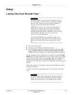
Страница 252: ...mbH Munzinger Straße 3 5 D 79111 Freiburg Germany Tel 49 761 45 43 0 Fax 49 761 45 43 233 Asian Headquarters GE Medical Systems Information Technologies Asia GE China Co Ltd 24th Floor Shanghai MAXDO Center 8 Xing Yi Road Hong Qiao Development Zone Shanghai 200336 P R China Tel 86 21 5257 4650 Fax 86 21 5208 2008 GE Medical Systems Information Technologies a General Electric Company going to marke...

Отзывы: