72R-10 0 0
9/05
ZT
X Series Automatic Transfer Switches
40-400 Amps
GE Zenith Controls
Operation and Maintenance Manual
e
Страница 1: ...72R 1000 9 05 ZTX Series Automatic Transfer Switches 40 400 Amps GE Zenith Controls Operation and Maintenance Manual e ...
Страница 2: ...ower for lighting and other critical loads by auto matically transferring from source 1 power to source 2 power in the event that source 1 voltage falls below preset limits Voltage sensing and system control is performed via a state of the art microcontroller located on the cabinet door It is designed to give highly accurate control of the transfer switch system All GE Zenith transfer switches are...
Страница 3: ...E Zenith representative Before installation it is necessary to store the transfer switch in a clean dry place protected from dirt and water Provide ample air circulation and heat if necessary to prevent condensation 5 to 95 non con densing 30 C to 75 C 22 F to 167 F 20 C to 65 C 4 F to 149 F Operating Storage Temperature Temperature Ambient Humidity CAUTION Due to hazardous voltage and current GE ...
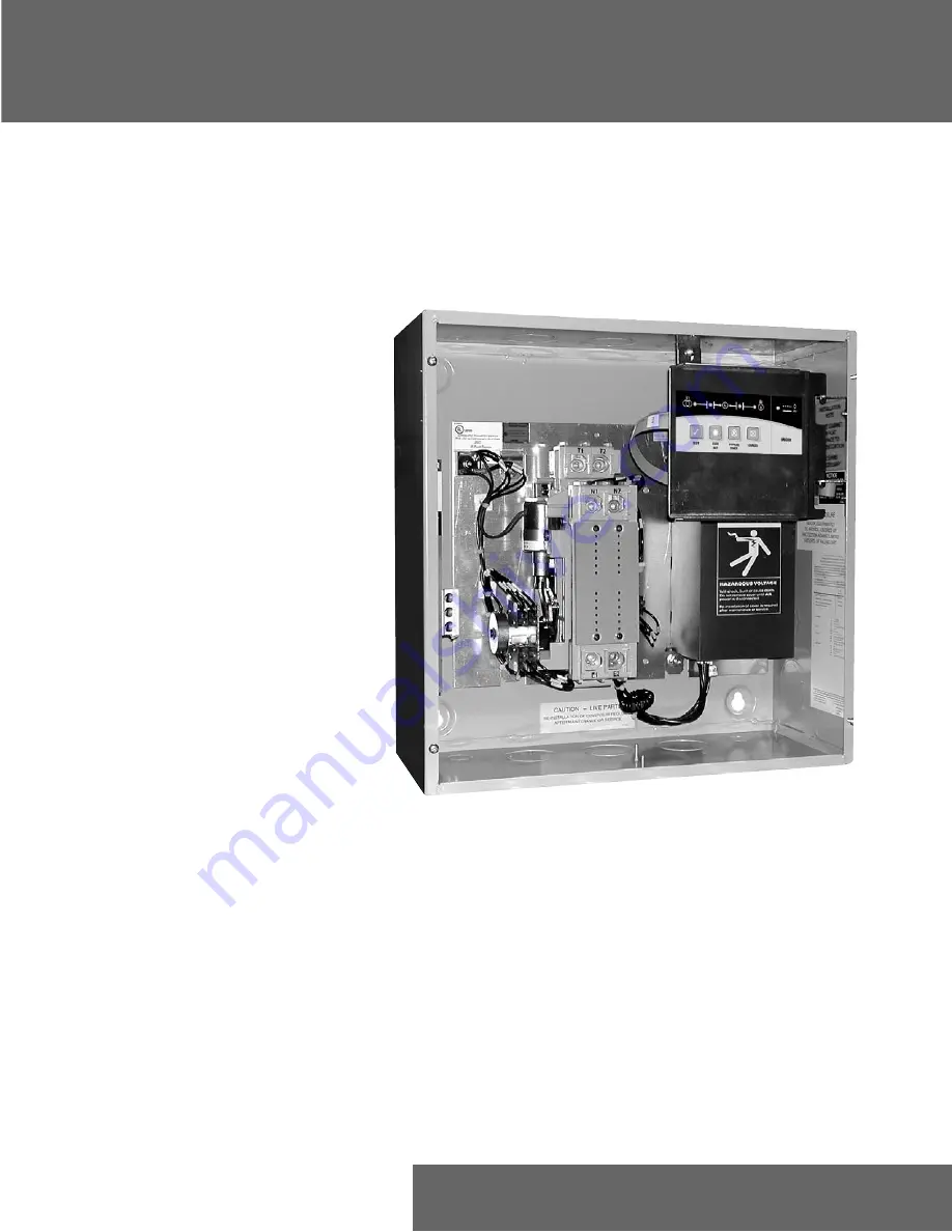
Страница 4: ... 6 AWG to 250 MCM 1 4 AWG to 600 MCM 3 6 AWG to 300 MCM 3 4 AWG to 300 MCM IEC Rating Only Installation cont d Figure 1 Power Panel Power Connections GE Zenith transfer switches are supplied with UL listed solderless screw type terminals as standard for the Normal Emergency and Load power connections Table 1 lists the number and sizes of cable lugs supplied as standard for each switch amp rating D...
Страница 5: ...cket Size Across Flats Torque Lb In Lb Ft 45 1 8 4 100 5 32 8 120 3 16 10 150 7 32 12 200 1 4 17 275 5 16 23 375 3 8 31 500 1 2 42 600 9 16 50 The engine start terminals are clearly identified by a label on the microcontroller backplate In the case of manual transfer switches or in other applications not requiring the microprocessor clearly marked terminal blocks are provided in the upper left cor...
Страница 6: ...battery is used to maintain the exerciser function in the event of power outage The battery should be replaced at least once a year If the battery is not installed and or replaced as recommended an exerciser set from the front panel will lose its settings during power outages and the exerciser will not work Note Battery life if reduced if neither source is avail able Typical battery life when both...
Страница 7: ...ED illumi nates Simultaneously the delay to generator timer W begins its timing cycle When the W time delay is com pleted the ATS will transfer to Generator the S1 position LED goes off and the S2 position LED illuminates Reclose the Utility breaker to retransfer to utility The delay to utility timer T begins its timing cycle Table 3 When the T timer has completed its timing cycle the ATS will tra...
Страница 8: ...e 5 Figure 6 on right shows the variations each of the 3 basic types of controllers can be adjusted to within its nominal voltage range Position Jumpers JP1 and JP2 as needed for voltage Position JP3 for frequency As with any other Jumper setting always remove power completely from the controller before making changes Note Do not change voltage Jumper positions without consulting service or techni...
Страница 9: ... S1 Utility Available Green LED When on indicates source is acceptable S1 Utility Position Green LED When on indicates ATS is connected to Utility S2 Generator Available Red LED When on indicates source is acceptable S2 Generator Position Red LED When on indicates ATS is connected to Generator Timing In phase Amber LED When blinking indicates the ATS is timing a Delay When on steady indicates the ...
Страница 10: ...t the desired exercise time The ATS will begin the Timer Sequence attempt to start S2 generator source and if S2 qualifies as a good source transfer the Load to S2 for the dura tion of the Generator Run Time After the Generator Run time has expired the timing sequence will restart and the Load will be transferred back to S1 after T time ending by running the U time and finally ending the call for ...
Страница 11: ...rciser At the exact time desired press and hold the EXER SET key for at least 1 second The ATS will immediately start an initial exercise by attempting to start the generator running through the Timers figure 3 and will either only start the generator or will start the generator and transfer the Load from S1 to S2 for the time duration of the exerciser interval 10 minutes Once the Exercise is comp...
Страница 12: ... diesel generator Because sources have a slight frequency difference sources come in and out of phase If ZTX In Phase Monitor is on The ZTX ATS Controller monitors both sources and transfers the Load at the ideal time to minimize back EMF conditions DANGER HAZARDOUS VOLTAGE Can Cause Severe Injury or Death Turn OFF all power before installation adjustment or removal of transfer switch or any of it...
Страница 13: ...s Circuit Breaker Main Breaker Panel All Loads Utility Source Transfer Switch Circuit Breaker Generator Source Loads Utility Panel Utility Source Transfer Switch Loads Circuit Breaker Distribution Panel Generator Source Partial Coverage System Total Coverage System Figure 9 Figure 10 ...
Страница 14: ...eration and Maintenance Manual 72R 1000 Typical Diagrams E3 N2 CCN SN SCOM SE E2 N1 N2 CCE E1 OPTIONAL 3 E2 N3 2 4 1 5 6 10 1 3 Power Circuit Schematic 40 240 Amps Power Panel Layout Interconnect Plug Figure 11 Figure 12 Figure 13 ...
Страница 15: ...n 40 to 200 Amps TAG DESCRIPTION VOLTAGE CN CE Solenoid Solenoid Plunger and Link SCN SCE Coil Cutout Switch A3 A4 Auxiliary Contacts 120 208 220 240 380 416 440 480 K 2207 K 2208 K 2208 K 2228 K 2212 K 2209 ALL 57P 1030 120 480V L 3078 L 3078 SCN SCE Coil Cutout Switch 600V L 4027 BR Rectifier ALL PS 5076 40 TO 200 AMPS Figure 14 Table 7 ...
Страница 16: ...ption Recommended as Spares 225 250 260 300 400 Cable Connection Lug S 2701 N 1 2 3 N E 1 2 3 N T 1 2 3 N Wire Size 4 600 MCM 4 600 MCM Coil Volts 208 220 240 K 2246B CN CE Solenoid SN SE Position Sense Limit Switch A3 A4 Auxiliary Contacts L 3078 BR Rectifier PS 5076 S 2701 S 2701 6 250 MCM T1 T2 T3 TN E1 E2 E3 EN SN A4 SE A3 CN CE BR N1 N2 N3 NN Figure 15 Table 8 ...
Страница 17: ...l not transfer in phase In Phase monitor not on Turn on In Phase monitor Frequency difference between S1 and Adjust Generator governor to hold S2 greater than 2Hz freqency closer to Utility ATS will not retain a Battery dead or missing Replace battery with a fresh industrial Set Automatic Exerciser grade Alkaline battery Timer In Phase LED constantly on Both sources locked in frequency or one Turn...
Страница 18: ...A Product of GE Consumer Industrial General Electric Company 830 West 40th Street Chicago IL 60609 USA 773 299 6600 Fax 773 247 7805 www geelectrical com g GE Zenith Controls ...