5-180
F60 Feeder Protection System
GE Multilin
5.6 GROUPED ELEMENTS
5 SETTINGS
5
This element is intended to apply a block signal to an overcurrent element to prevent an operation when current is flowing
in a particular direction. The direction of current flow is determined by measuring the phase angle between the current from
the phase CTs and the line-line voltage from the VTs, based on the 90° or quadrature connection. If there is a requirement
to supervise overcurrent elements for flows in opposite directions, such as can happen through a bus-tie breaker, two
phase directional elements should be programmed with opposite element characteristic angle (ECA) settings.
To increase security for three phase faults very close to the VTs used to measure the polarizing voltage, a voltage memory
feature is incorporated. This feature stores the polarizing voltage the moment before the voltage collapses, and uses it to
determine direction. The voltage memory remains valid for one second after the voltage has collapsed.
The main component of the phase directional element is the phase angle comparator with two inputs: the operating signal
(phase current) and the polarizing signal (the line voltage, shifted in the leading direction by the characteristic angle, ECA).
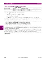
The following table shows the operating and polarizing signals used for phase directional control:
MODE OF OPERATION:
•
When the function is “Disabled”, or the operating current is below 5%
×
CT nominal, the element output is “0”.
•
When the function is “Enabled”, the operating current is above 5%
×
CT nominal, and the polarizing voltage is above
the
PRODUCT SETUP
DISPLAY PROPERTIES
VOLTAGE CUT-OFF LEVEL
value, the element output is dependent on
the phase angle between the operating and polarizing signals:
– The element output is logic “0” when the operating current is within polarizing voltage ±90°.
– For all other angles, the element output is logic “1”.
•
Once the voltage memory has expired, the phase overcurrent elements under directional control can be set to block or
trip on overcurrent as follows:
– When
BLOCK WHEN V MEM EXP
is set to “Yes”, the directional element will block the operation of any phase
overcurrent element under directional control when voltage memory expires.
– When
BLOCK WHEN V MEM EXP
is set to “No”, the directional element allows tripping of phase overcurrent elements
under directional control when voltage memory expires.
In all cases, directional blocking will be permitted to resume when the polarizing voltage becomes greater than the ‘polariz-
ing voltage threshold’.
SETTINGS:
•
PHASE DIR 1 SIGNAL SOURCE:
This setting is used to select the source for the operating and polarizing signals.
The operating current for the phase directional element is the phase current for the selected current source. The polar-
izing voltage is the line voltage from the phase VTs, based on the 90° or ‘quadrature’ connection and shifted in the
leading direction by the element characteristic angle (ECA).
•
PHASE DIR 1 ECA:
This setting is used to select the element characteristic angle, i.e. the angle by which the polariz-
ing voltage is shifted in the leading direction to achieve dependable operation. In the design of the UR-series elements,
a block is applied to an element by asserting logic 1 at the blocking input. This element should be programmed via the
ECA setting so that the output is
logic 1 for current in the non-tripping direction
.
•
PHASE DIR 1 POL V THRESHOLD:
This setting is used to establish the minimum level of voltage for which the phase
angle measurement is reliable. The setting is based on VT accuracy. The default value is “0.700 pu”.
•
PHASE DIR 1 BLOCK WHEN V MEM EXP:
This setting is used to select the required operation upon expiration of
voltage memory. When set to "Yes", the directional element blocks the operation of any phase overcurrent element
under directional control, when voltage memory expires; when set to "No", the directional element allows tripping of
phase overcurrent elements under directional control.
PHASE
OPERATING
SIGNAL
POLARIZING SIGNAL V
pol
ABC PHASE SEQUENCE
ACB PHASE SEQUENCE
A
angle of IA
angle of VBC
×
(1
∠
ECA)
angle of VCB
×
(1
∠
ECA)
B
angle of IB
angle of VCA
×
(1
∠
ECA)
angle of VAC
×
1
∠
ECA)
C
angle of IC
angle of VAB
×
(1
∠
ECA)
angle of VBA
×
(1
∠
ECA)
Содержание F60
Страница 10: ...x F60 Feeder Protection System GE Multilin TABLE OF CONTENTS ...
Страница 30: ...1 20 F60 Feeder Protection System GE Multilin 1 5 USING THE RELAY 1 GETTING STARTED 1 ...
Страница 138: ...4 28 F60 Feeder Protection System GE Multilin 4 2 FACEPLATE INTERFACE 4 HUMAN INTERFACES 4 ...
Страница 454: ...5 316 F60 Feeder Protection System GE Multilin 5 10 TESTING 5 SETTINGS 5 ...
Страница 500: ...7 14 F60 Feeder Protection System GE Multilin 7 1 COMMANDS 7 COMMANDS AND TARGETS 7 ...
Страница 508: ...8 8 F60 Feeder Protection System GE Multilin 8 2 FAULT LOCATOR 8 THEORY OF OPERATION 8 ...
Страница 522: ...10 12 F60 Feeder Protection System GE Multilin 10 6 DISPOSAL 10 MAINTENANCE 10 ...
Страница 660: ...B 116 F60 Feeder Protection System GE Multilin B 4 MEMORY MAPPING APPENDIX B B ...
Страница 706: ...E 10 F60 Feeder Protection System GE Multilin E 1 IEC 60870 5 104 APPENDIX E E ...
Страница 718: ...F 12 F60 Feeder Protection System GE Multilin F 2 DNP POINT LISTS APPENDIX F F ...
Страница 728: ...H 8 F60 Feeder Protection System GE Multilin H 2 ABBREVIATIONS APPENDIX H H Z Impedance Zone ...
Страница 730: ...H 10 F60 Feeder Protection System GE Multilin H 3 WARRANTY APPENDIX H H ...


