


GE Multilin
L30 Line Current Differential System
3-29
3 HARDWARE
3.3 PILOT CHANNEL COMMUNICATIONS
3
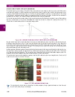
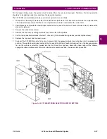
The switch settings for the internal and loop timing modes are shown below:
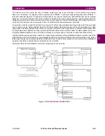
e) G.703 TEST MODES
In
minimum remote loopback
mode, the multiplexer is enabled to return the data from the external interface without any
processing to assist in diagnosing G.703 line-side problems irrespective of clock rate. Data enters from the G.703 inputs,
passes through the data stabilization latch which also restores the proper signal polarity, passes through the multiplexer
and then returns to the transmitter. The differential received data is processed and passed to the G.703 transmitter module
after which point the data is discarded. The G.703 receiver module is fully functional and continues to process data and
passes it to the differential Manchester transmitter module. Since timing is returned as it is received, the timing source is
expected to be from the G.703 line side of the interface.
Figure 3–32: G.703 MINIMUM REMOTE LOOPBACK MODE
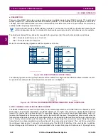
In
dual loopback mode
, the multiplexers are active and the functions of the circuit are divided into two with each receiver/
transmitter pair linked together to deconstruct and then reconstruct their respective signals. Differential Manchester data
enters the Differential Manchester receiver module and then is returned to the differential Manchester transmitter module.
Likewise, G.703 data enters the G.703 receiver module and is passed through to the G.703 transmitter module to be
returned as G.703 data. Because of the complete split in the communications path and because, in each case, the clocks
are extracted and reconstructed with the outgoing data, in this mode there must be two independent sources of timing. One
source lies on the G.703 line side of the interface while the other lies on the differential Manchester side of the interface.
Figure 3–33: G.703 DUAL LOOPBACK MODE
DMR
DMX
G7X
G7R
DMR = Differential Manchester Receiver
DMX = Differential Manchester Transmitter
G7X = G.703 Transmitter
G7R = G.703 Receiver
842774A1.CDR
DMR
DMX
G7X
G7R
DMR = Differential Manchester Receiver
DMX = Differential Manchester Transmitter
G7X = G.703 Transmitter
G7R = G.703 Receiver
842775A1.CDR
Содержание L30
Страница 10: ...x L30 Line Current Differential System GE Multilin TABLE OF CONTENTS ...
Страница 30: ...1 20 L30 Line Current Differential System GE Multilin 1 5 USING THE RELAY 1 GETTING STARTED 1 ...
Страница 58: ...2 28 L30 Line Current Differential System GE Multilin 2 4 SPECIFICATIONS 2 PRODUCT DESCRIPTION 2 ...
Страница 126: ...4 30 L30 Line Current Differential System GE Multilin 4 3 FACEPLATE INTERFACE 4 HUMAN INTERFACES 4 ...
Страница 370: ...5 244 L30 Line Current Differential System GE Multilin 5 10 TESTING 5 SETTINGS 5 ...
Страница 396: ...6 26 L30 Line Current Differential System GE Multilin 6 5 PRODUCT INFORMATION 6 ACTUAL VALUES 6 ...
Страница 450: ...10 10 L30 Line Current Differential System GE Multilin 10 4 INSTANTANEOUS ELEMENTS 10 APPLICATION OF SETTINGS 10 ...
Страница 464: ...A 10 L30 Line Current Differential System GE Multilin A 1 PARAMETER LISTS APPENDIX A A ...
Страница 600: ...C 30 L30 Line Current Differential System GE Multilin C 7 LOGICAL NODES APPENDIX C C ...
Страница 610: ...D 10 L30 Line Current Differential System GE Multilin D 1 IEC 60870 5 104 APPENDIX D D ...
Страница 622: ...E 12 L30 Line Current Differential System GE Multilin E 2 DNP POINT LISTS APPENDIX E E ...
Страница 634: ...F 12 L30 Line Current Differential System GE Multilin F 3 WARRANTY APPENDIX F F ...
Страница 644: ...x L30 Line Current Differential System GE Multilin INDEX ...